NUUMCB05Mini Reading System
Magnisight Inc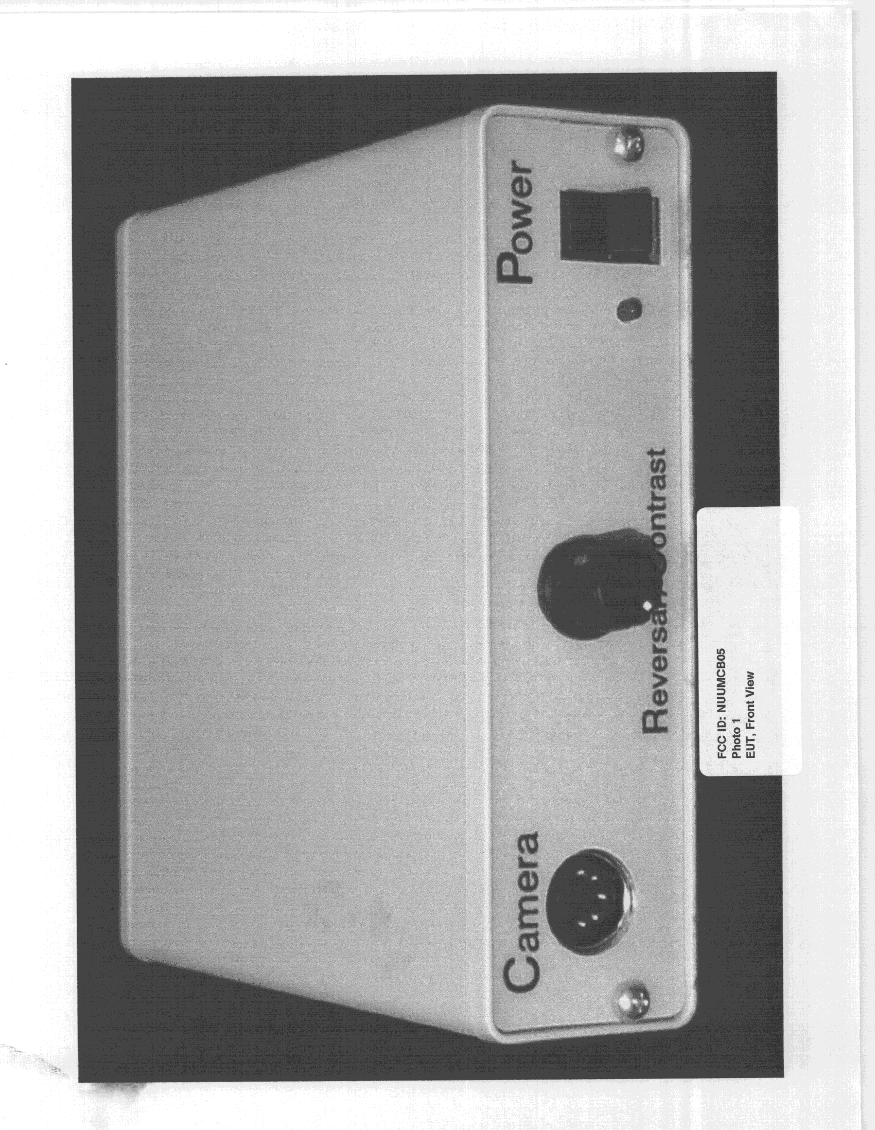
Click to zoom
Application Details
- Equipment Class
- HID - Part 15 TV Interface Device
- Date of Grant
- Dec 22, 1998
- Application Purpose
- Original Equipment
- Date of Application
- Apr 23, 1998
- Equipment Note
- Mini Reading System
- Frequency Range
- 60.00000000 - 72.00000000
- Company
- Magnisight Inc
- Country
- United States
Documents & Files
Document Text
Text extracted from the exhibit documents filed with the FCC. Open a document above to read the original.
Test Report
FCC ID: NUUMCB05 6 CONDUCTED EMISSIONS DATA The initial step in collecting conducted data is a spectrum analyzer peak scan of the measurement range. Significant peaksare recorded. Test Date: December 10, 1998 UST Project: 98-116 Customer: Magnisight, Inc. Model: Portable Mini Reader System Model X-MRS-7 Test Data (dBm) LISN Loss (dB) Results (uV) Margin Below Limit (dB) Frequency (MHz) Phase Neutral Phase Neutral Cable Factor (dB) Phase Neutral FCC Class A Limits (uV) Phase Neutral 3.3 -67.0 -90.0 0.0 0.0 0.3 103.5 7.3 250.0 7.7 30.7 9.6 -61.0 -86.0 0.0 0.0 0.5 211.3 11.9 250.0 1.5 26.4 10.7 -69.0 -91.0 0.1 0.1 0.6 86.1 6.8 250.0 9.3 31.3 15.5 -84.0 -67.0 0.1 0.1 0.6 15.3 108.4 250.0 24.3 7.3 15.2 -80.0 -67.0 0.1 0.1 0.5 24.0 107.2 250.0 20.4 7.4 21.7 -85.0 -68.0 0.1 0.1 0.7 13.8 97.7 250.0 25.2 8.2 Sample Calculations:Results uV = Antilog ((-67.0 + 0.0 + 0.3 + 107)/20) = 103.5Conversion from dBm to dBuV = 107 dBResultsReviewed By: Name: Tim R. Johnson FCC ID: NUUMCB05 7 RADIATED EMISSION DATA 7.1 The following data lists the significant emission frequencies, measured levels, correction factor (includes cable and antenna corrections), the corrected reading, plus the limit. Test Date:December 9, 1998 UST Project:98-116 Customer:Magnisight, Inc. Model:Portable Mini Reader System Model X-MRS-7 Frequency (MHz) Test Data (dBm) @3m Ant. Factor + Cable Attenuation Results (uV/m) @3m FCC Limits (uV/m) @3m Margin Below Limit (dB) 32.4-92.015.332.6100.09.7 47.7-86.012.346.1100.06.7 66.7 -83.5*11.656.9100.04.9 124.0-88.014.245.6150.010.3 162.1-85.015.675.5150.06.0 324.0-94.019.039.8200.014.0 * = Quasi Peak Results Reviewed By: Name: Tim R. Johnson FCC ID: NUUMCB05 7.2 Field Strength Calculation The field strength is calculated by adding the Antenna Factor and Cable Factor, and subtracting the Amplifier Gain (if any) from the measured reading. The basic equation with a sample calculation is as follows: FS = RA + CF - AG whereFS = Field Strength RA = Receiver Amplitude CF = Correction Factor = Antenna Factor + Cable Loss AG = Amplifier Gain FS (uV/m) = Antilog [( -92.0 + 15.3 + 107 ) / 20] = 32.6 FCC ID: NUUMCB05 8 MEASUREMENT OF MAXIMUM RF OUTPUT LEVEL The output level of the EUT was measured across a 75 Ω resistance with the input level supplied by the camera, sold with the system. Channel 4 was also investigated but Channel 4 was worse than Channel 3. Test Date:December 9, 1998 UST Project:98-116 Customer:Magnisight, Inc. Model:Portable Mini Reader System Model X-MRS-7 Frequency (MHz) Measured Reading (uV) Limit (uV) Video = 67.2718393000 Audio = 71.80318.4671.1 The Limits were calculated as follows: Video Signal Limit = 346.4 x SQRT (75Ω) = 3000 uV Audio Signal Limit = 77.5 x SQRT (75Ω) = 671.1 uV Results Reviewed By: Name: Tim R. Johnson FCC ID: NUUMCB05 9 MEASUREMENT OF RF OUTPUT SPURIOUS EMISSIONS The RF output emissions of the EUT was measured across a 75 Ω resistance with the input level supplied by the camera, sold with the system. The system was examined in frequency from 30 MHz to 2 GHz for output Channels 3 and 4. Channel 4 was worse than Channel 3. The RBW was set to 30 kHz for all measurements. Test Date:December 9, 1998 UST Project:98-116 Customer:Magnisight, Inc. Model:Portable Mini Reader System Model X-MRS-7 Frequency (MHz) Measured Reading (uV) Limit (uV) No Measurable Emissions Results Reviewed By: Name: Tim R. Johnson FCC ID: NUUMCB05 10 MEASUREMENT OF RECEIVER ANTENNA INPUT TERMINAL SPURIOUS EMISSIONS The receiver antenna input terminal emissions of the EUT was measured across a 75 Ω resistance with the input level supplied by the camera, sold with the system. The system was examined in frequency from 30 MHz to 1 GHz for output Channel 4. Channel 4 was worse than Channel 3. The RBW was set to 10 kHz for all measurements. Test Date:December 11, 1998 UST Project:98-116 Customer:Magnisight, Inc. Model:Portable Mini Reader System Model X-MRS-7 Frequency (MHz) Measured Reading (uV) Limit (uV) 65.72.53.0 The Limits were calculated as follows: Limit = 0.346 x SQRT (75Ω) = 3.0 uV Results Reviewed By: Name: Tim R. Johnson
Test Report
FCC ID: NUUMCB05 6 CONDUCTED EMISSIONS DATA The initial step in collecting conducted data is a spectrum analyzer peak scan of the measurement range. Significant peaksare recorded. Test Date: December 10, 1998 UST Project: 98-116 Customer: Magnisight, Inc. Model: Portable Mini Reader System Model X-MRS-7 Test Data (dBm) LISN Loss (dB) Results (uV) Margin Below Limit (dB) Frequency (MHz) Phase Neutral Phase Neutral Cable Factor (dB) Phase Neutral FCC Class A Limits (uV) Phase Neutral 3.3 -67.0 -90.0 0.0 0.0 0.3 103.5 7.3 250.0 7.7 30.7 9.6 -61.0 -86.0 0.0 0.0 0.5 211.3 11.9 250.0 1.5 26.4 10.7 -69.0 -91.0 0.1 0.1 0.6 86.1 6.8 250.0 9.3 31.3 15.5 -84.0 -67.0 0.1 0.1 0.6 15.3 108.4 250.0 24.3 7.3 15.2 -80.0 -67.0 0.1 0.1 0.5 24.0 107.2 250.0 20.4 7.4 21.7 -85.0 -68.0 0.1 0.1 0.7 13.8 97.7 250.0 25.2 8.2 Sample Calculations:Results uV = Antilog ((-67.0 + 0.0 + 0.3 + 107)/20) = 103.5Conversion from dBm to dBuV = 107 dBResultsReviewed By: Name: Tim R. Johnson FCC ID: NUUMCB05 7 RADIATED EMISSION DATA 7.1 The following data lists the significant emission frequencies, measured levels, correction factor (includes cable and antenna corrections), the corrected reading, plus the limit. Test Date:December 9, 1998 UST Project:98-116 Customer:Magnisight, Inc. Model:Portable Mini Reader System Model X-MRS-7 Frequency (MHz) Test Data (dBm) @3m Ant. Factor + Cable Attenuation Results (uV/m) @3m FCC Limits (uV/m) @3m Margin Below Limit (dB) 32.4-92.015.332.6100.09.7 47.7-86.012.346.1100.06.7 66.7 -83.5*11.656.9100.04.9 124.0-88.014.245.6150.010.3 162.1-85.015.675.5150.06.0 324.0-94.019.039.8200.014.0 * = Quasi Peak Results Reviewed By: Name: Tim R. Johnson FCC ID: NUUMCB05 7.2 Field Strength Calculation The field strength is calculated by adding the Antenna Factor and Cable Factor, and subtracting the Amplifier Gain (if any) from the measured reading. The basic equation with a sample calculation is as follows: FS = RA + CF - AG whereFS = Field Strength RA = Receiver Amplitude CF = Correction Factor = Antenna Factor + Cable Loss AG = Amplifier Gain FS (uV/m) = Antilog [( -92.0 + 15.3 + 107 ) / 20] = 32.6 FCC ID: NUUMCB05 8 MEASUREMENT OF MAXIMUM RF OUTPUT LEVEL The output level of the EUT was measured across a 75 Ω resistance with the input level supplied by the camera, sold with the system. Channel 4 was also investigated but Channel 4 was worse than Channel 3. Test Date:December 9, 1998 UST Project:98-116 Customer:Magnisight, Inc. Model:Portable Mini Reader System Model X-MRS-7 Frequency (MHz) Measured Reading (uV) Limit (uV) Video = 67.2718393000 Audio = 71.80318.4671.1 The Limits were calculated as follows: Video Signal Limit = 346.4 x SQRT (75Ω) = 3000 uV Audio Signal Limit = 77.5 x SQRT (75Ω) = 671.1 uV Results Reviewed By: Name: Tim R. Johnson FCC ID: NUUMCB05 9 MEASUREMENT OF RF OUTPUT SPURIOUS EMISSIONS The RF output emissions of the EUT was measured across a 75 Ω resistance with the input level supplied by the camera, sold with the system. The system was examined in frequency from 30 MHz to 2 GHz for output Channels 3 and 4. Channel 4 was worse than Channel 3. The RBW was set to 30 kHz for all measurements. Test Date:December 9, 1998 UST Project:98-116 Customer:Magnisight, Inc. Model:Portable Mini Reader System Model X-MRS-7 Frequency (MHz) Measured Reading (uV) Limit (uV) No Measurable Emissions Results Reviewed By: Name: Tim R. Johnson FCC ID: NUUMCB05 10 MEASUREMENT OF RECEIVER ANTENNA INPUT TERMINAL SPURIOUS EMISSIONS The receiver antenna input terminal emissions of the EUT was measured across a 75 Ω resistance with the input level supplied by the camera, sold with the system. The system was examined in frequency from 30 MHz to 1 GHz for output Channel 4. Channel 4 was worse than Channel 3. The RBW was set to 10 kHz for all measurements. Test Date:December 11, 1998 UST Project:98-116 Customer:Magnisight, Inc. Model:Portable Mini Reader System Model X-MRS-7 Frequency (MHz) Measured Reading (uV) Limit (uV) 65.72.53.0 The Limits were calculated as follows: Limit = 0.346 x SQRT (75Ω) = 3.0 uV Results Reviewed By: Name: Tim R. Johnson
Contact Information
Applicant
Brian M. Smith(President)
Test Firm
US TechSandy McEnery
Technical Specifications
| # | Rule Parts | Frequency Range | Power Output | Tolerance |
|---|---|---|---|---|
| 1 | 15B | 60 MHz - 72 MHz | - | % |