NV8MRD85IMarine Audio Player
Estone Technology Inc.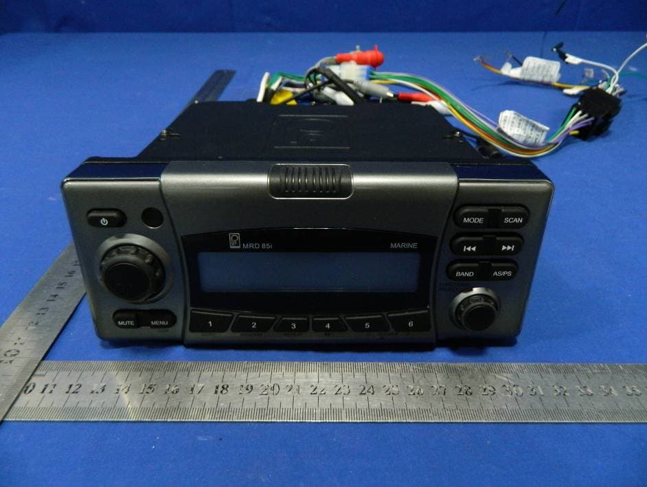
Click to zoom
Application Details
- Equipment Class
- DSS - Part 15 Spread Spectrum Transmitter
- Date of Grant
- Jan 27, 2013
- Application Purpose
- Original Equipment
- Date of Application
- Jan 27, 2013
- Equipment Note
- Marine Audio Player
- Frequency Range
- 2402.00000000 - 2480.00000000
- Company
- Estone Technology Inc.
- Country
- United States
Documents & Files
Document Text
Text extracted from the exhibit documents filed with the FCC. Open a document above to read the original.
Users Manual
MRD85i OWNER’S MANUAL BUILT-IN BLUETOOTH WIRELESS AUDIO SIRIUS READY DMD READY (Digital Music Device like iPod®, MP3, Smartphone devices) USB READY FLIP DOWN FRONT PANEL SD MEMORY CARD READY AM/FM MARINE STEREO RDS READY rev 12192012 2 T A B L E O F C O N T E N T S Installation....................................................................................3 Wiring Diagram.............................................................................5 Button Description........................................................................7 Basic Operation............................................................................8 Radio Operation..........................................................................10 Sirius Operation..........................................................................12 iPod® Operation..........................................................................15 Bluetooth Operation....................................................................16 Auxiliary Operation.....................................................................16 USB Operation............................................................................17 SD Card Operation......................................................................18 Compatible Accessories...............................................................20 Troubleshooting..........................................................................21 Technical Specifications...............................................................22 Warranty Information...................................................................23 Warranty Registration..................................................................25 3 I N S T A L L A T I O N IMPORTANT! Before mounting be sure there is sufficient room to accommodate the unit and that there is sufficient ventilation. Before installing the unit, connect the wiring temporarily making sure the system works properly. Only use the parts included with the unit to ensure proper installation. Receiver should be mounted within 30º (+ or— 15º) from Horizontal. If installation angle exceeds 30° from horizontal, the unit might not give its optimum performance. Avoid installing the unit where it would be subject to high temperatures such as direct sunlight or hot air from heaters or the engine or where it would be subject to dust, dirt or excessive vibration. Use the template provided to make the cutout. With the front panel down insert the 4 provided screws. Use the 5mm nut and bracket provided to stabilize the rear of the radio. Be sure to mount the unit to a strong, solid surface which will not give way under the stress of waves pounding the hull. 4 Optional Mounting Techniques Optional gimbal mount bracket installation Model # GM-MRD80 Optional Overhead / Under Dash mount installation Model # RM-10 5 W I R I N G D I A G R A M Wiring Details: Use the wired plug end (Pigtail) provided to make power and speaker connections according to the diagram below. Using this connector will make it easy to disconnect the radio for adding additional features or service. Removing the factory plug end will void warranty. 6 Wire Color Function Yellow 1 B+ (+12VDC) Green w/stripe 2 Rear Left Speaker- Green 3 Rear Left Speaker+ Red 4 ACC (+12VDC) White w/stripe 5 Front Left Speaker- White 6 Front Left Speaker+ Blue 7 Relay Trigger Gray w/stripe 8 Front Right Speaker- Gray 9 Front Right Speaker+ Black 10 Ground (Neg) Violet w/stripe 11 Rear Right Speaker- Violet 12 Rear Right Speaker+ Power Wire Specifications: Yellow Wire - Connect this wire to a constant +12V source. Red Wire - Connect this wire to a switched +12V source such as an ignition or accessory switch. Black Wire - Connect this wire to the negative battery terminal or other good power ground. Blue Wire - This wire outputs a 12V signal when the MRD80 turns on. It is used to remotely turn on external amplifiers. Notes: Use the included plug/wire bundle to connect to the power source and speakers. 7 B U T T O N D E S C R I P T I O N The Yellow, Red and Black power wires should be 14AWG or larger depending on the length to the battery. NEVER operate the unit without the proper power and ground wire. NEVER ground the speaker leads and NEVER allow the speaker leads to come in contact with each other. The speaker wire should be at least 16 gauge or larger. Be sure to observe the correct polarity on the speaker connections Use quality crimp connectors to connect wires together. Seal the connection well with electrical tape. NEVER operate the unit without proper fusing. Fuse holder must be located within 2 feet from the battery. This fuse is to protect the vessel, not the electronics. In case of a short, the fuse will blow instead of the wire burning up. Using other than the recommended fuse ratings at the battery and at the unit may cause damage to the unit and will void your warranty. Whenever possible, use cable ties, mounting clamps and similar wiring aids. Adding stress relief loop to wiring is also advisable to prevent straining or breakage. If after reading the directions you feel uncomfortable about installing the unit, or not equipped or competent to do so, you should have this installed by a professional installer 22. RESET 8 B A S I C O P E R A T I O N 1. - Power Button 2. IR Receiver 3. Volume UP/DOWN Knob 4. MUTE – Mute Button 5. MENU/DISP – Menu/Display Button 6. 1/INTRO - Preset 1/Scan Button 7. 2/RANDOM - Preset 2/Random Button 8. 3/REPEAT - Preset 3/Repeat Button 9. 4/ - Preset 4/(Play/Pause) Button 10. 5/ - Preset 5/Folder down (optional) 11. 6/ - Preset 6/Directory up (optional) 12. LCD Display 13. Front Panel Latch Button 14. Function/Select Knob 15. BAND - Band Button 16. AS/PS - Auto Store and Preset Scan Button 17. – Control Button 18. MODE - Mode Button 19. SCAN – Scan Button 20. SD Card Slot 21. DMD Drawer SWITCHING ON/OFF THE UNIT Press button to turn on the unit. Press and hold button for…
Text truncated - open the document above for the full version.
Cover Letter(s)
Confidentiality Request Letter Revision History Reason for Amendment (current / obsolete) From To Approved Date Initial Release (obsolete) 1.0 1.0 Nov-14-2006 Adding CFR 2.459 (obsolete) 1.0 2.0 August – 11 - 2008 Updated company template & Added text box (current) 2.0 3.0 Jan-31-2012 Estone Technology Inc. (2013-01-18) To: Federal Communications Commission Office of Engineering and Technology Equipment Authorization Division 7345 Oakland Mills Road Columbia, Maryland 21046 Subject: Permanent Confidentiality Request for FCC ID: NV8MRD85I We hereby request confidential treatment of information accompanying this application as outlined below: - Block diagram - Operation description - Schematic The above materials contain trade secrets and proprietary information not customarily released to the public. The public disclosure of these materials may be harmful to the applicant and provide unjustified benefits to its competitors. The applicant understands that pursuant to Section 0.457 & 0.459 of the Rules, disclosure of this application and all accompanying documentation will not be made before the date of the Grant for this application. Sincerely, Signature Jeff Ji / Engineer E-mail: : [email protected] Phone: 419-549-5727 Fax: 419-536-5406 Address : 3324 secor road #8, Toledo, OH 43606 USA
ID Label/Location Info
Label Location Proposed Label Location on EUT
ID Label/Location Info
Marine Audio Player FCC ID: NV8MRD85I Model Number: MRD85i Made in China This device complies with Part 15 of the FCC Rules. Operation is subject to the following two conditions: (1) this device may not cause harmful interference, and (2) this device must accept any interference received, including interference that may cause undesired operation.
Internal Photos
BT Module Antenna
Test Report
TRF No:FCC 15.247/A Page 1 of 36 Report No: ES121219115E ELECTROMAGNETIC EMISSIONS COMPLIANCE REPORT INTENTIONAL RADIATOR CERTIFICATION TO FCC PART 15 SUBPARTC REQUIREMENT OF Marine Audio Player MODEL No.: MRD85i, MRD85 FCC ID: NV8MRD85I Trade Mark: REPORT NO: ES121219115E ISSUE DATE: January 17, 2013 Prepared for ESTONE TECHNOLOGY INC. 3324 secor road #8, Toledo, OH 43606 USA. Prepared by SHENZHEN EMTEK CO., LTD Bldg 69, Majialong Industry Zone, Nanshan District, Shenzhen, Guangdong, China TEL : 86-755-26954280 FAX: 86-755-26954282 TRF No:FCC 15.247/A Page 3 of 36 Report No: ES121219115E Ta b l e o f C o n t e n t s 1. GENERAL INFORMATION ................................................................................................. 5 1.1. PRODUCT DESCRIPTION........................................................................................................................... 5 1.2. RELATED SUBMITTAL(S) / GRANT (S) ..................................................................................................... 5 1.3. TEST METHODOLOGY.............................................................................................................................. 5 1.4. SPECIAL ACCESSORIES............................................................................................................................ 5 1.5. EQUIPMENT MODIFICATIONS.................................................................................................................. 5 1.6. TEST FACILITY........................................................................................................................................ 6 2. SYSTEM TEST CONFIGURATION .................................................................................... 7 2.1. EUT CONFIGURATION............................................................................................................................. 7 2.2. EUT EXERCISE........................................................................................................................................ 7 2.3. TEST PROCEDURE.................................................................................................................................... 7 2.4. LIMITATION............................................................................................................................................. 7 2.5. CONFIGURATION OF TESTED SYSTEM................................................................................................... 11 2.6. EQUIPMENT USED IN TESTED SYSTEM.................................................................................................. 11 2.7. DESCRIPTION OF TEST MODES............................................................................................................... 11 3. SUMMARY OF TEST RESULTS ....................................................................................... 12 4. CONDUCTED EMISSIONS TEST ..................................................................................... 13 4.1. MEASUREMENT PROCEDURE:................................................................................................................ 13 4.2. TEST SET-UP (BLOCK DIAGRAM OF CONFIGURATION) ....................................................................... 13 4.3. MEASUREMENT EQUIPMENT USED: ...................................................................................................... 13 4.4. CONDUCTED EMISSION LIMIT............................................................................................................... 13 4.5. MEASUREMENT RESULT:....................................................................................................................... 13 4.6. CONDUCTED MEASUREMENT PHOTOS: ................................................................................................. 13 5. RADIATED EMISSION TEST ............................................................................................ 14 5.1. MEASUREMENT PROCEDURE................................................................................................................. 14 5.2. TEST SET-UP (BLOCK DIAGRAM OF CONFIGURATION) ....................................................................... 15 5.3. MEASUREMENT EQUIPMENT USED: ...................................................................................................... 16 5.4. MEASUREMENT RESULT........................................................................................................................ 17 5.5. RADIATED MEASUREMENT PHOTOS: .................................................................................................... 22 6. CHANNEL SEPARATION TEST ....................................................................................... 24 6.1. MEASUREMENT PROCEDURE................................................................................................................. 24 6.2. TEST SET-UP (BLOCK DIAGRAM OF CONFIGURATION) ....................................................................... 24 6.3. MEASUREMENT EQUIPMENT USED: ...................................................................................................... 24 6.4. MEASUREMENT RESULTS:..................................................................................................................... 24 7. 20DB BANDWIDTH TEST .................................................................................................. 27 7.1. MEASUREMENT PROCEDURE................................................................................................................. 27 7.2. TEST SET-UP (BLOCK DIAGRAM OF CONFIGURATION) ....................................................................... 27 7.3. MEASUREMENT EQUIPMENT USED: ...................................................................................................... 27 TRF No:FCC 15.247/A Page 4 of 36 Report No: ES121219115E 7.4. MEASUREMENT RESULTS:.................................…
Text truncated - open the document above for the full version.
Test Setup Photos
Radiated Measurement Photos:
Contact Information
Applicant
Jeff JI(engineer)
Test Firm
EMTEK (Shenzhen) Co., Ltd.David Lee
Technical Specifications
| # | Rule Parts | Frequency Range | Power Output |
|---|---|---|---|
| 1 | 15C | 2.40 GHz - 2.48 GHz | 1.57 mW |
Other Applications from Estone Technology Inc.

NV8-R8
Jan 17, 2013TABLET PC
Equipment Class
JBP - Part 15 Class B Computing Device Peripheral
NV8IN-STREAM
May 17, 2012Audio Player
Equipment Class
DSS - Part 15 Spread Spectrum Transmitter