NVCRMI0004Medium power gas remote meter interface
Whisper Communications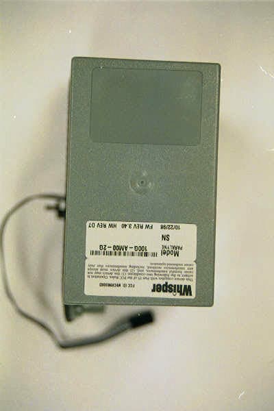
Click to zoom
Application Details
- Equipment Class
- DSS - Part 15 Spread Spectrum Transmitter
- Date of Grant
- May 12, 1999
- Application Purpose
- Original Equipment
- Date of Application
- Mar 29, 1999
- Equipment Note
- Medium power gas remote meter interface
- Frequency Range
- 902.00000000 - 928.00000000
- Company
- Whisper Communications
- Country
- United States
Documents & Files
Document Text
Text extracted from the exhibit documents filed with the FCC. Open a document above to read the original.
RF Exposure Info
March 30, 1999 Federal Communications Commission Equipment Authorization Division 7435 Oakland Mills Road Columbia, MD 21046 Subject: Maximum Permissible Exposure calculations for FCC ID: NVCRMI0004 To whom it may concern, Whisper is submitting a low power transmitter for the Gas Remote Meter Interface. The unit has a low power frequency hopping spread spectrum radio operating in the 902 - 928 MHz range with a radiated output power of 12.1 mW. Assuming a worst case of no duty cycle. For an Isotropic radiator the surface area of a sphere can be used to determine the area over which the transmitter energy is radiated. Surface area of a sphere = 4*Π*radius 2 In the case where there is antenna gain, the worst case energy density is increased by the antenna gain. The exposure level can be calculated as follows for the –3.0 dBi antenna gain: MPE distance = (output power * duty cycle * 10 (antenna gain/10)/(4*Π*Exposure Limit (mW / cm 2 ) 1/2 For the -3.0 dBi Antenna NVCRMI0004 MPE distance = (92 mW*1*0.5/ 4*3.14*1) 1/2 = 1.91 cm = .75 in If you have any questions please do not hesitate to call me. Sincerely, Chris Byleckie Technical Director Electronic Compliance Laboratories
Test Report
A903019.DOC1 15.247 Certification15.247 Certification FCC ID: NVCRMI0004FCC ID: NVCRMI0004 EMI TEST REPORTEMI TEST REPORT Medium Power Gas RMIMedium Power Gas RMI Prepared forPrepared for Whisper Communication Inc.Whisper Communication Inc. 3200 Coronado Drive3200 Coronado Drive Santa Clara, CA 95054Santa Clara, CA 95054 Tel: (408) 490-3800Tel: (408) 490-3800 Fax: (408) 490-3801Fax: (408) 490-3801 Prepared byPrepared by Electronic Compliance Laboratories Inc.Electronic Compliance Laboratories Inc. 1249 Birchwood Dr.1249 Birchwood Dr. Sunnyvale, CA 94089Sunnyvale, CA 94089 Tel: (408) 747-1490Tel: (408) 747-1490 Fax: (408) 747-1495Fax: (408) 747-1495 Test Report Number: A903019Test Report Number: A903019 Date of Test: November 13, 1998Date of Test: November 13, 1998 If this Document is reproduced, it must be reproduced in it's entirety A903019.DOC2 Table of Contents 1.0 Test Facility...................................................................................................3 2.0 Test Equipment.............................................................................................3 3.0 EUT................................................................................................................4 4.0 Support Equipment......................................................................................4 5.0 Equipment Configuration.............................................................................4 6.0 Summary Of Tests........................................................................................5 APPENDIX A 15.247 Spread Spectrum Plots....................................................8 APPENDIX B 15.205 Restricted Band Data.....................................................24 APPENDIX C 15.209 Radiated Emissions.......................................................26 APPENDIX D Antenna and Antenna Connector.............................................28 APPENDIX E Test Set-up Photographs..........................................................31 A903019.DOC3 1.0TEST FACILITY Name: Electronic Compliance Laboratories Location:1249 Birchwood Dr. Sunnyvale, CA 94089 Site Filing:A site description is on file at the Federal Communications Commission P.O. Box 429 Columbia, MD 21045 Types of Sites:Open Field Radiated and Indoor Screen Room (Line Conducted). All sites are constructed and calibrated to meet ANSI C63.4-1994 requirements. Test facility is recognized by the National Voluntary Laboratory Accreditation Program for satisfactory compliance with criteria established in Title 15, Part 285 Code of Federal Regulations. NVLAP Code:20089 effective through: March 31, 1999 2.0TEST EQUIPMENT DescriptionManufacturerModelSN EMI ReceiverHP8546A3325A00137 Power MeterHP437B3125U13399 Power SensorHP84813318A16275 Spectrum AnalyzerHP8563E3137A01183 PreampHP8447F3113A05849 PreampHP8449B3008A00527 LISNEMANS-25/22532 Biconical AntennaEMEM 6912677 Log Periodic AntEMEM 6950858 Double Ridge HornEMEM 69616231 Filter BP 1.2-4 GHzFSYHM1160-11SS001 Filter BP 4-10 GHzFSYHM2950-15SS001 Filter BP10-18 GHzFSYHP8601-7SS001 A903019.DOC4 3.0EUT Product:Medium Power Gas RMI Model Number:100G-XX00-XX Serial Number:0001ABFFA Description: The Whisper Communication Inc. Medium Power Gas RMI is a spread spectrum frequency hopping radio transceiver operating in the 902 - 928 MHz band that resides in a gas meter "trace" housing. The RMI unit transmits gas consumption information to a remote cell. 4.0SUPPORT EQUIPMENT Equipment Type:N/A Model Number:N/A Serial Number:N/A Manufacturer:N/A : 5.0 EQUIPMENT CONFIGURATION All of the equipment and cables were placed in worst case positions to maximize emissions. Interconnecting cables were of the type and length specified in the individual equipment requirements. Grounding was in accordance with the manufacturers requirements and conditions for intended use. EUT PORT CONNECTED TO CABLE TYPE A903019.DOC5 6.0SUMMARY OF TESTS The Medium Power Gas RMI is a frequency hopping spread spectrum (FHSS) radio system operating in the 902-928 MHz band. Tests were performed with one standard antenna. Test firmware resident in the EUT and was used to do the test. Digital emissions testing was not performed on this version of the RMI since the Digital control board is the same for both the Low and Medium power versions. 15.209 testing was done on the Low Power version and is documented in report A809003. 6.115.247(a)(1) FREQUENCY HOPPING SYSTEMS The Medium Power Gas RMI uses 50 channels, each 120 kHz wide. The system hops using pseudorandom sequences. On average, each channel is used equally. 6.1.115.247(a)(1)(i) CHANNEL UTILIZATION Three spectrum analyzer plots labeled "CHANNEL UTILIZATION 903 - 912", "CHANNEL UTILIZATION 912 - 920", and "CHANNEL UTILIZATION 920 - 928" . The total number of channels shown is 67, which exceeds the minimum requirement of 50. The channels used have nominal center frequencies of 902 through 918 MHz. Three spectrum analyzer MAX HOLD plots labeled " BANDWIDTH" show the 20 dB bandwidth of the hopping channel to be < 500 kHz (127/ 133 / 130 kHz) at the low/midband/high frequencies of 904.32 / 914.94 / 925.38 MHz. Plots are in Appendix A. Zero span spectrum analyzer plots labeled "CHANNEL DWELL TIME" shows Worst case transmission time in a given slot: 270ms msec elapsed time, <100 % Medium Power Gas RMI Rev. E Maximum allowed:400 msec. The test plots are in Appendix A. A903019.DOC6 6.1.215.247(b) MAXIMUM PEAK OUTPUT POWER The maximum power of the hopping channel to be +19.67 dBm or .92 W. The EUT was made to transmit uninterrupted random data on each of the low/mid/high channels. The output was fed directly via cable soldered to the antenna connection point on the circuit board, spectrum analyzer set on MAX HOLD with no additional attenuation. See Appendix A for Plots. Pout = +19.67 dBm / 92 mW Limit: +30 dBm / 1 W maximum power -3.0 dBi Internal Antenna EIRP = +19.67 (peak power) -3 dBi (peak gain, dBi) = +16.67 dBm / .046 W EIRP 6.1.31…
Text truncated - open the document above for the full version.
Contact Information
Applicant
Joe Barrea(Product Manager)
408-490-3800Fax: 408-490-3801
Technical Contact
electronic compliance laboratorieschris byleckie
[email protected]408-747-1490
Non-Technical Contact
electronic compliance laboratories
[email protected]408-747-1490
Test Firm
Electronic Compliance LaboratoriesChip Matheny
[email protected]408-747-1490
Technical Specifications
| # | Rule Parts | Frequency Range | Power Output |
|---|---|---|---|
| 1 | 15C | 902 MHz - 928 MHz | 46.00 mW |
Other Applications from Whisper Communications
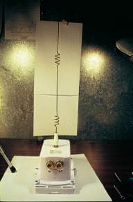
NVC-BSR-0002
Apr 11, 1999Whisper Remote Metering System
Equipment Class
DSS - Part 15 Spread Spectrum Transmitter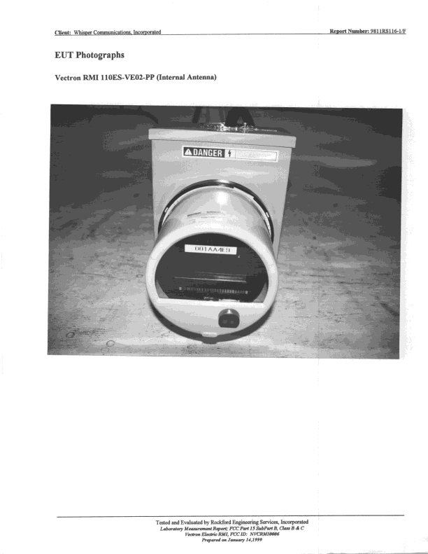
NVCRMI0006
Mar 28, 1999DSS - Part 15 Spread Spectrum Transmitter
Equipment Class
DSS - Part 15 Spread Spectrum Transmitter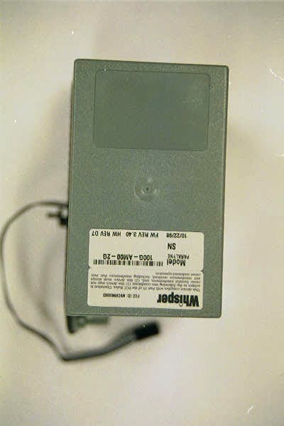
NVCRMI0003
Jan 26, 1999DSS - Part 15 Spread Spectrum Transmitter
Equipment Class
DSS - Part 15 Spread Spectrum TransmitterNVCRMI0002
Jan 25, 1999Meter Reading Transmitter
Equipment Class
DSS - Part 15 Spread Spectrum Transmitter
NVC-BSR-0001
Aug 12, 1998DSS - Part 15 Spread Spectrum Transmitter
Equipment Class
DSS - Part 15 Spread Spectrum Transmitter