NVQWTHRSCN01WeatherScene RF Modem Link
McQ Inc.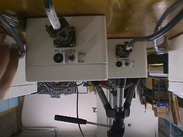
Click to zoom
Application Details
- Equipment Class
- TNB - Licensed Non-Broadcast Station Transmitter
- Date of Grant
- Mar 24, 1999
- Application Purpose
- Original Equipment
- Date of Application
- Jan 05, 1999
- Equipment Note
- WeatherScene RF Modem Link
- Frequency Range
- 150.00000000 - 174.00000000
- Company
- McQ Inc.
- Country
- United States
Documents & Files
Document Text
Text extracted from the exhibit documents filed with the FCC. Open a document above to read the original.
Users Manual
System Innovations, Inc. WeatherScene™ Operators Manual November, 1998 ws_oprman.doc ii Table of Contents Table of Contents.......................................................................................ii Section 1......................................................................................................1 General Information....................................................................................................1 System Overview....................................................................................................1 Optional Features....................................................................................................2 Section 2......................................................................................................4 Theory of Operation....................................................................................................4 Remote Site Hardware.............................................................................................4 RPU Power System.................................................................................................6 Communications Architecture.................................................................................7 Control Display Unit Hardware...................................................................................9 Overview.................................................................................................................9 Control Display Unit Personal Computer.................................................................9 CDU Software.......................................................................................................10 Optional Equipment..................................................................................................10 Remote Device Activation.....................................................................................10 Infrared Illuminator...............................................................................................10 Section 3.....................................................................................................11 Software and Control.................................................................................................11 Overview...............................................................................................................11 Windows® 95 Procedures.....................................................................................12 Fixed and Laptop Displays....................................................................................12 Getting Started......................................................................................................12 Status Window......................................................................................................16 Command Area.........................................................................................................17 RPU IDs................................................................................................................17 Weather Information Area.........................................................................................20 Road Conditions Information Area........................................................................20 Solar Radiance Information Area...........................................................................20 Floating Menu Functions/Features.............................................................................21 Communication Features.......................................................................................26 Sequencer Configuration.......................................................................................32 Measurement Scheduler.........................................................................................34 Weather-Based Alarms..........................................................................................34 Periodic Reports....................................................................................................36 Advanced Features................................................................................................38 Save JPEG Files....................................................................................................39 Section 4.....................................................................................................41 Video Data Management...........................................................................................41 Overview...............................................................................................................41 Video Data Backup...............................................................................................42 Weather Information Archive Data............................................................................44 Overview...............................................................................................................44 Weather POD Archive Data Format.....................................................................44 Road Condition Archive Data Format....................................................................45 iii Appendix A................................................................................................46 WeatherScene™ System Specifications.....................................................................46 iv WeatherScene™ Operators Manual Revision Sheet Date of ChangeDescription of Change 11/01/98Version 1.0 issued. 1 Section 1 General Information System Overview WeatherScene™ is a state-of-the-art, highway monitoring system. It collects video images and weather data at remote locations, with optional capabilities such as traffic flow, solar radiance, precipitation, and highway roadbed information (refer to fig. 1.1). The information is compressed and transmitted via a communication architecture to …
Text truncated - open the document above for the full version.
Users Manual
System Innovations, Inc. WeatherScene™ Operators Manual November, 1998 ws_oprman.doc ii Table of Contents Table of Contents.......................................................................................ii Section 1......................................................................................................1 General Information....................................................................................................1 System Overview....................................................................................................1 Optional Features....................................................................................................2 Section 2......................................................................................................4 Theory of Operation....................................................................................................4 Remote Site Hardware.............................................................................................4 RPU Power System.................................................................................................6 Communications Architecture.................................................................................7 Control Display Unit Hardware...................................................................................9 Overview.................................................................................................................9 Control Display Unit Personal Computer.................................................................9 CDU Software.......................................................................................................10 Optional Equipment..................................................................................................10 Remote Device Activation.....................................................................................10 Infrared Illuminator...............................................................................................10 Section 3.....................................................................................................11 Software and Control.................................................................................................11 Overview...............................................................................................................11 Windows® 95 Procedures.....................................................................................12 Fixed and Laptop Displays....................................................................................12 Getting Started......................................................................................................12 Status Window......................................................................................................16 Command Area.........................................................................................................17 RPU IDs................................................................................................................17 Weather Information Area.........................................................................................20 Road Conditions Information Area........................................................................20 Solar Radiance Information Area...........................................................................20 Floating Menu Functions/Features.............................................................................21 Communication Features.......................................................................................26 Sequencer Configuration.......................................................................................32 Measurement Scheduler.........................................................................................34 Weather-Based Alarms..........................................................................................34 Periodic Reports....................................................................................................36 Advanced Features................................................................................................38 Save JPEG Files....................................................................................................39 Section 4.....................................................................................................41 Video Data Management...........................................................................................41 Overview...............................................................................................................41 Video Data Backup...............................................................................................42 Weather Information Archive Data............................................................................44 Overview...............................................................................................................44 Weather POD Archive Data Format.....................................................................44 Road Condition Archive Data Format....................................................................45 iii Appendix A................................................................................................46 WeatherScene™ System Specifications.....................................................................46 iv WeatherScene™ Operators Manual Revision Sheet Date of ChangeDescription of Change 11/01/98Version 1.0 issued. 1 Section 1 General Information System Overview WeatherScene™ is a state-of-the-art, highway monitoring system. It collects video images and weather data at remote locations, with optional capabilities such as traffic flow, solar radiance, precipitation, and highway roadbed information (refer to fig. 1.1). The information is compressed and transmitted via a communication architecture to …
Text truncated - open the document above for the full version.
Cover Letter(s)
System Innovations, Inc. 1551 Forbes Street Fredericksburg, Virginia 22405 Date: January 6, 1999 Federal Communications Commission Authorization and Evaluation Division 7435 Oakland Mills Columbia, Maryland 21046 I the undersigned, hereby authorize Rhein Tech Laboratories, Inc. to act on our behalf in all matters relating to applications for equipment certification, including the signing of all documents relation to these matters. Any and all acts carried out by Rhein tech Laboratories, Inc. relating to matters for equipment certification on our behalf shall have the same effect as acts of our own. This authorization is valid until revoked in writing. Signed: Title: Date:
Cover Letter(s)
System Innovations, Inc. 1551 Forbes Street Fredericksburg, Virginia 22405 Date: January 6, 1999 Federal Communications Commission Authorization and Evaluation Division 7435 Oakland Mills Columbia, Maryland 21046 I the undersigned, hereby authorize Rhein Tech Laboratories, Inc. to act on our behalf in all matters relating to applications for equipment certification, including the signing of all documents relation to these matters. Any and all acts carried out by Rhein tech Laboratories, Inc. relating to matters for equipment certification on our behalf shall have the same effect as acts of our own. This authorization is valid until revoked in writing. Signed: Title: Date:
External Photos
5.5RADIATED MEASUREMENT PHOTOS FIGURE 30: WEATHERSCENE (FRONT) FIGURE 31: AC ADAPTERS FIGURE 32: WEATHERSCENE (BACK)
External Photos
5.5RADIATED MEASUREMENT PHOTOS FIGURE 30: WEATHERSCENE (FRONT) FIGURE 31: AC ADAPTERS FIGURE 32: WEATHERSCENE (BACK)
ID Label/Location Info
System Innovations, Inc., Inc. FIGURE 1: FCC ID LABEL This device complies with the FCC, part 15 rules. Operation is subject to the following two conditions: 1) This device may not cause harmful interference. 2) This device must accept any interference received, including interference that may cause undesired operation. FCC ID: NVQWTHRSCN01 FIGURE 2: LOCATION OF LABEL ON EUT BOTTOM OF EUT Label Placement
ID Label/Location Info
System Innovations, Inc., Inc. FIGURE 1: FCC ID LABEL This device complies with the FCC, part 15 rules. Operation is subject to the following two conditions: 1) This device may not cause harmful interference. 2) This device must accept any interference received, including interference that may cause undesired operation. FCC ID: NVQWTHRSCN01 FIGURE 2: LOCATION OF LABEL ON EUT BOTTOM OF EUT Label Placement
ID Label/Location Info
FIGURE 1: FCC ID LABEL FIGURE 2: LOCATION OF LABEL ON EUT BOTTOM OF EUT Label Placement FCC ID: NVQWTHRSCN01
Internal Photos
Part # 29-Serial #WxSENSOR Rev. B Component Side Part # 29-Serial #WxSENSOR Rev. B Solder Side Part #31-Serial#WxVisTX Rev. C component side Part #31-Serial#WxVisTX Rev. C solder side Part# 13-Serial# WxVisRX Rev. C component side Part# 13-Serial# WxVisRX Rev. C solder side Pod #10 component side Pod #10 solder side Pod #19 component side Pod #19 solder side Power Supply RFCIU pcb MAX3241 component side RFCIU pcb MAX3241 solder side RFCIU pcb processor rev. C 0220 component side RFCIU pcb processor rev. C 0220 solder side RFICU pcb SVR DIG Rev. D component side RFICU pcb SVR DIG Rev. D solder side RFICU pcb SVR RF Rev. A 00186 component side RFICU pcb SVR RF Rev. A 00186 solder side RFU pcb 00189 component side RFU pcb 00189 solder side RFU pcb SVT 00224 component side RFU pcb SVT 00224 solder side RFU pcb DSP uP Rev. B #011B component side RFU pcb DSP uP Rev. B #011B solder side RFU SVR Dig component side RFU SVR Dig solder side
Schematics
6.0SCHEMATICS
Schematics
6.0SCHEMATICS
Test Report
5.0MEASUREMENT PLOTS 5.1 FCC Part 2.987(d): Modulated Characteristics FIGURE 3: FCC PART 2.987(D): MODULATION CHARACTERISTICS-151.5125MHZ FIGURE 4: FCC PART 2.987(D): MODULATION CHARACTERISTICS-151.64000MHZ 5.2 FCC Part 2.989(B): Occupied Bandwidth FIGURE 5: FCC PART 2.989(B): OCCUPIED BANDWIDTH-151.51000MHZ Measured occupied bandwidths: 22.5kHz at -23.0dB down from the peak mean power. 22.5kHz Peak -23.0dB FIGURE 6: FCC PART 2.989(B): OCCUPIED BANDWIDTH-151.64388MHZ Measured occupied bandwidths: 20.0kHz at -23.0dB down from the peak mean power. 20.0kHz Peak -23.dB 5.3 FCC Part 2.991 and Part 90.217(a): Spurious Emissions at Antenna Terminals FIGURE 7: RFCIU-LOWER FREQUENCY-UNMODULATED 40dB External Attenuation FIGURE 8: RFCIU-UPPER FREQUENCY-UNMODULATED 40dB External Attenuation FIGURE 9: RFCIU-START 150KHZ-STOP 30.00MHZ-MODULATED 20dB External Attenuation FIGURE 10: RFCIU-START 30.00MHZ-STOP 100.00MHZ-MODULATED 20dB External Attenuation FIGURE 11: RFCIU-START 145.00MHZ-STOP 155.00MHZ-MODULATED 20dB External Attenuation FIGURE 12: RFCIU-START 155.00MHZ-STOP 200.00MHZ-MODULATED 20dB External Attenuation FIGURE 13: RFCIU-START 200.00MHZ-STOP 1.000GHZ-MODULATED 20dB External Attenuation FIGURE 14: RPU-LOWER FREQUENCY-UNMODULATED 40dB External Attenuation FIGURE 15: RPU-UPPER FREQUENCY-UNMODULATED 40dB External Attenuation FIGURE 16: RPU-START 150KHZ-STOP 30.00MHZ-MODULATED 20dB External Attenuation FIGURE 17: RPU-START 30.00MHZ-STOP 100.00MHZ-MODULATED 20dB External Attenuation FIGURE 18: RPU-START 100.00MHZ-STOP 200.00MHZ-MODULATED 20dB External Attenuation FIGURE 19: RPU-START 200.00MHZ-STOP 500.00MHZ-MODULATED 20dB External Attenuation FIGURE 20: RPU-START 500.00MHZ-STOP 1.000GHZ-MODULATED 20dB External Attenuation
Test Report
ÕÕÕÕÕÕÕÕÕÕÕÕÕÕÕÕÕÕÕÕÕÕÕÕÕÕÕÕÕÕÕÕÕÕÕÕÕÕÕÕÕÕÕÕÕÕÕ APPLICATION FOR PART 90 TYPE CERTIFICATION TRANSMITTER VHF (MANCHESTER FSK) System Innovations, Inc. 1551 Forbes Street Fredericksburg, VA 22405 MODEL: WeatherScene RF Modem Link FCC ID: NVQWTHRSCN01 November 30, 1998 REPORT PREPARED BY: EMI Technician:K. Franck Schuppius Administrative Writer:Dixie L. Shetter Rhein Tech Laboratories, Inc. Document Number: 980628 No part of this report may be reproduced without the full written approval of Rhein Tech Laboratories, Inc. This report concerns (check one):Original Grant: X Class II Change: Equipment Type: Transmitter Deferred grant requested per 47 CFR 0.457 (d) (1) (ii)?Yes:No: X If yes, defer until: Date Company name agrees to notify the Commission by: (date) of the intended date of announcement of the product so that the grant can be issued on that date. FCC ID: NVQWTHRSCN01 i TABLE OF CONTENTS 1.0GENERAL INFORMATION...................................................................................................................1 1.1PRODUCT DESCRIPTION-OVERVIEW....................................................ERROR! BOOKMARK NOT DEFINED. 1.2PRODUCT DESCRIPTION-SPECIFICATIONS.............................................ERROR! BOOKMARK NOT DEFINED. 1.3PRODUCT DESCRIPTION-CHARACTERISTICS (WEATHERSCENE)............ERROR! BOOKMARK NOT DEFINED. 1.4PRODUCT DESCRIPTION-CHARACTERISTICS (TRANSMITTER)................ERROR! BOOKMARK NOT DEFINED. 1.5PRODUCT DESCRIPTION-CHARACTERISTICS (RECEIVER)......................ERROR! BOOKMARK NOT DEFINED. 1.6RELATED SUBMITTAL(S)/GRANT(S)..........................................................................................................2 1.7TEST SYSTEM DETAILS............................................................................................................................2 1.8BLOCK DIAGRAM OF TESTED SYSTEM.................................................ERROR! BOOKMARK NOT DEFINED. 1.9TEST METHODOLOGY..............................................................................................................................3 1.10TEST FACILITY........................................................................................................................................3 2.0PRODUCT LABELING.............................................................ERROR! BOOKMARK NOT DEFINED. 3.0SYSTEM TEST CONFIGURATION......................................................................................................4 3.1JUSTIFICATION.........................................................................................................................................4 3.2EUT EXERCISE SOFTWARE......................................................................................................................4 3.3SPECIAL ACCESSORIES.............................................................................................................................4 3.4CONFORMANCE STATEMENT....................................................................................................................5 4.0STANDARD REQUIREMENTS..............................................................................................................6 4.1FCC PART 90.217(A): EXEMPTION FROM TECHNICAL STANDARDS...........................................................6 4.2FCC PART PART 2.987(D): MODULATION REQUIREMENTS AND CHARACTERISTICS....................................6 4.3FCC PART 2.985: RF OUTPUT POWER.....................................................................................................7 4.3.1 Methods of Measurement and Test Results..............................................................................................7 4.4FCC PART 2.989(B) AND ANSI C63.4, SECTION 13.1.7: OCCUPIED BANDWIDTH......................................8 4.5FCC PART 2.997(A)(1): FREQUENCY SPECTRUM TO BE INVESTIGATED......................................................8 4.6FCC PART 2.991 AND PART 90.217(A): SPURIOUS EMISSIONS AT ANTENNA TERMINALS...........................8 4.6.1 Method of measurement:........................................................................................................................8 4.7FCC PART 2.993 AND PART 90.217(A): FIELD STRENGTH OF SPURIOUS RADIATION..................................9 4.7.1Method of measurement:.................................................................................................................9 4.8FCC PART 90.213 AND PART 2.995(A): FREQUENCY STABILITY FUNCTION OF TEMPERATURE....................9 4.8.1 Method of Measurement:........................................................................................................................9 4.8.2 Test Results:..........................................................................................................................................9 5.0MEASUREMENT PLOTS.........................................................ERROR! BOOKMARK NOT DEFINED. 5.1 FCC PART 2.987(D): MODULATED CHARACTERISTICS.............................ERROR! BOOKMARK NOT DEFINED. 5.2 FCC PART 2.989(B): OCCUPIED BANDWIDTH..........................................ERROR! BOOKMARK NOT DEFINED. 5.3 FCC PART 2.991 AND PART 90.217(1): SPURIOUS EMISSIONS AT ANTENNA TERMINALSERROR! BOOKMARK NOT DEFINED. 5.4 FCC PART 2.993: FIELD STRENGTH OF SPURIOUS RADIATION......................................................................10 5.5: RADIATED MEASUREMENT PHOTOS........................................................ERROR! BOOKMARK NOT DEFINED. 6.0SCHEMATICS.......................................................................................................................................11 7.0 FIELD STRENGTH CALCULATION, AND RADIATED TEST METHODOLOGY.............................12 7.1FIELD STRENGTH CALCULATION............................................................................................................12 7.2 RADIATED MEASUREMENT.....................................…
Text truncated - open the document above for the full version.
Test Report
5.0MEASUREMENT PLOTS 5.1 FCC Part 2.987(d): Modulated Characteristics FIGURE 3: FCC PART 2.987(D): MODULATION CHARACTERISTICS-151.5125MHZ FIGURE 4: FCC PART 2.987(D): MODULATION CHARACTERISTICS-151.64000MHZ 5.2 FCC Part 2.989(B): Occupied Bandwidth FIGURE 5: FCC PART 2.989(B): OCCUPIED BANDWIDTH-151.51000MHZ Measured occupied bandwidths: 22.5kHz at -23.0dB down from the peak mean power. 22.5kHz Peak -23.0dB FIGURE 6: FCC PART 2.989(B): OCCUPIED BANDWIDTH-151.64388MHZ Measured occupied bandwidths: 20.0kHz at -23.0dB down from the peak mean power. 20.0kHz Peak -23.dB 5.3 FCC Part 2.991 and Part 90.217(a): Spurious Emissions at Antenna Terminals FIGURE 7: RFCIU-LOWER FREQUENCY-UNMODULATED 40dB External Attenuation FIGURE 8: RFCIU-UPPER FREQUENCY-UNMODULATED 40dB External Attenuation FIGURE 9: RFCIU-START 150KHZ-STOP 30.00MHZ-MODULATED 20dB External Attenuation FIGURE 10: RFCIU-START 30.00MHZ-STOP 100.00MHZ-MODULATED 20dB External Attenuation FIGURE 11: RFCIU-START 145.00MHZ-STOP 155.00MHZ-MODULATED 20dB External Attenuation FIGURE 12: RFCIU-START 155.00MHZ-STOP 200.00MHZ-MODULATED 20dB External Attenuation FIGURE 13: RFCIU-START 200.00MHZ-STOP 1.000GHZ-MODULATED 20dB External Attenuation FIGURE 14: RPU-LOWER FREQUENCY-UNMODULATED 40dB External Attenuation FIGURE 15: RPU-UPPER FREQUENCY-UNMODULATED 40dB External Attenuation FIGURE 16: RPU-START 150KHZ-STOP 30.00MHZ-MODULATED 20dB External Attenuation FIGURE 17: RPU-START 30.00MHZ-STOP 100.00MHZ-MODULATED 20dB External Attenuation FIGURE 18: RPU-START 100.00MHZ-STOP 200.00MHZ-MODULATED 20dB External Attenuation FIGURE 19: RPU-START 200.00MHZ-STOP 500.00MHZ-MODULATED 20dB External Attenuation FIGURE 20: RPU-START 500.00MHZ-STOP 1.000GHZ-MODULATED 20dB External Attenuation
Test Report
FCC PART 2.201 EMISSION, MODULATION, AND TRANSMISSION CHARACTERISTICS- EMISSION DESIGNATOR The first symbol indicates the type of modulation on the transmitter carrier. The second symbol indicates the type of signal modulating the transmitter carrier. The third symbol indicates the type of transmitted information. Designator for the WeatherScene RF Modem Link : F1D FCC PART 2.202 (A): NECESSARY BANDWIDTH Necessary bandwidth Description of emission FormulaCalculationDesignation of emission Manchester encoded Digital data FSK Data transmission Bn=2M+2D8.4 kHz*8K40 with D peak frequency deviation (i.e. half the difference between the maximum and minimum value of the instantaneous frequency - the instantaneous frequency in Hz is the time rate of change in phase in radians divided by 2), M maximum modulation frequency in Hz, and Bn Necessary bandwidth in Hz. *Calculations and data test results: D = (2x∆fp) / 2 = (2x3) / 2 = 3 kHzandfm = 1.2 kHz = M
Contact Information
Applicant
Brian McQuiddy(Director of Customer Operations)
Technical Contact
Rhein Tech Laboratories, Inc.Bruno Clavier
[email protected]703-689-0368
360 Herndon Parkway, Suite 1400 · Herndon, Virginia · United States
Non-Technical Contact
Rhein Tech Laboratories, Inc.Dixie L Shetter
[email protected]703-689-0368
Technical Specifications
| # | Rule Parts | Frequency Range | Power Output | Emission | Tolerance |
|---|---|---|---|---|---|
| 1 | 90.217(b) | 150 MHz - 174 MHz | 18.20 mW | 22K5F1D | 10.0000000000 ppm |