NW3ETXMOD9000AStereo Transmitter Module
E-Zone Research & Development Inc.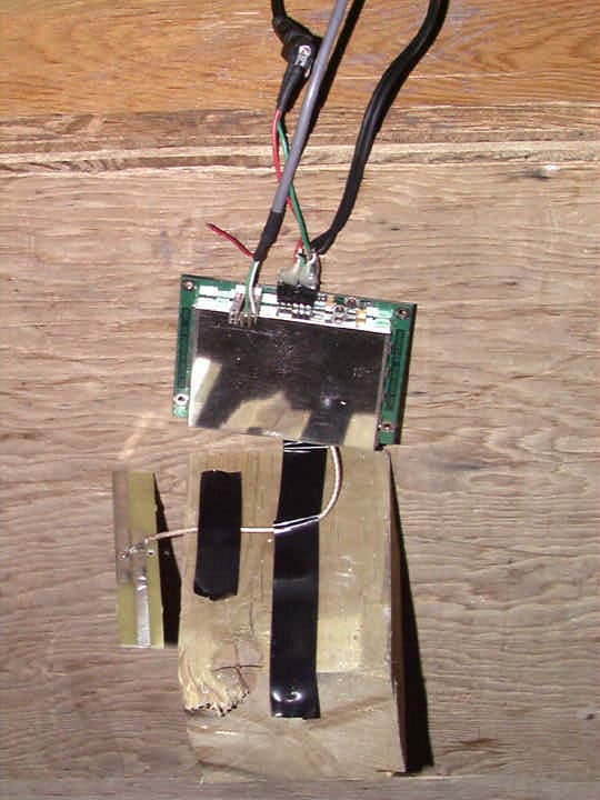
Click to zoom
Application Details
- Equipment Class
- DXX - Part 15 Low Power Communication Device Transmitter
- Date of Grant
- Feb 06, 2000
- Application Purpose
- Original Equipment
- Date of Application
- Nov 10, 1999
- Equipment Note
- Stereo Transmitter Module
- Frequency Range
- 902.20000000 - 927.80000000
- Country
- Canada
Documents & Files
Document Text
Text extracted from the exhibit documents filed with the FCC. Open a document above to read the original.
Users Manual
Title: EZone TX Module V1.0 Manual/Specifications Calgary Alberta Canada Document No. 308A08-Z Sheet 1 of 17 Rev. 1.0 Ezone TX module Version 1.0 902-928 MHz ISM Band Transmitter Manual/Specifications THIS DOCUMENT IS THE PROPERTY OF E-ZONE NETWORKS INC, CALGARY, ALBERTA, CANADA. IT SHALL NOT BE USED FOR ANY PURPOSE EXCEPT THE MANUFACTURE OF ARTICLES FOR E-ZONE NETWORKS WITHOUT WRITTEN PERMISSION OF E-ZONE NETWORKS. Title: EZone TX Module V1.0 Manual/Specifications Calgary Alberta Canada Document No. 308A08-Z Sheet 2 of 17 Rev. 1.0 Revision History RevECO No.DateComments 1.011/15/99Initial FCC submission document Title: EZone TX Module V1.0 Manual/Specifications Calgary Alberta Canada Document No. 308A08-Z Sheet 3 of 17 Rev. 1.0 Table of Contents 1.0Purpose.........................................................................................................................................................4 2.0Scope.............................................................................................................................................................4 3.0Test Description.........................................................................................................................................4 3.1Test Configuration.......................................................................................................................................4 3.2Equipment Description..............................................................................................................................4 3.2.1Mode of Operation for FCC EMI Test................................................................................................4 3.2.2Mode of Operation for Normal Operation..........................................................................................5 3.3Antenna Requirement – per 15.203........................................................................................................5 3.4Schematics..................................................................................................................................................6 3.4.1902MHz – 928MHz ISM band Transmitter Module V1.0 Schematics.......................................6 3.4.2Circuit Description – per 2.1033(b)4............................................................................................10 3.4.3TOP OF TRANSMITTER BOARD...............................................................................................11 3.4.4BOTTOM OF TRANSMITTER BOARD......................................................................................12 3.5Labeling Requirements – Per 2.1033(B)(7)........................................................................................13 3.6Typical Calibration procedure for Transmitter module......................................................................13 3.6.1TX software system overview.......................................................................................................13 3.6.2Output Power Calibration Procedure...........................................................................................15 Title: EZone TX Module V1.0 Manual/Specifications Calgary Alberta Canada Document No. 308A08-Z Sheet 4 of 17 Rev. 1.0 1.0 Purpose The purpose of this report is to provide a more detailed description of the connections, usage, schematics, and parts lists. This report is to be used in combination with the EMI TEST REPORT to be submitted to FCC for certification of the Ezone TX module product V1.0 900MHz ISM band Transmitter. 2.0 Scope The document although used primarily in combination with the EMI TEST REPORT for FCC certification submission, does contain information included in documents such as the users manual, and test procedures. 3.0 Test Description 3.1 Test Configuration Unit Name – Processor, Monitor, Printer, Cable, Etc. (indent for features of a unit) Style/Model/Pa rt No. Serial Number Obj. of test 1 2 0 V 2 2 0 V Comments/FCC ID# Ezone TX module V1.0ETXMOD9000A001 ++ 3.2 Equipment Description This module is to be used in various models of a compact Entertainment System for Fitness Industry. A typical system consists of an audio/video system with self-contained audio CD, audio cassette tape, and television with wireless headphone. The audio channel of one of the three sources is selected and transmitted to wireless headphones using this TX module. 3.2.1 Mode of Operation for FCC EMI Test The EUT that was used during the testing was connected through an interface cable. This cable provided both the serial communications used to control the EUT and supply audio signals necessary for operation. This cable was connected to a laptop computer located remotely. This laptop computer contained special test software that allowed the transmitter frequency, power output, and modulation to be changed manually. The transmitter power output was adjusted until the radiated level was in compliance with the maximum FCC allowable limit. It must be emphasized that the power output, and modulation adjustments cannot be adjusted in normal operation of the TX module. These values are only adjusted when calibrating the TX module during manufacture and during the FCC EMI testing setup. The location of the Laptop was such that it did not interfere with the emission measurements made at the test site. The laptop and special software used on the laptop would was only used in order to allow modifications of power output and modulation during the tests for compliance. During the manufacturing calibration these settings would be loaded into a non-volatile EEPROM on a manufactured unit (see additional information on manufacturing calibration procedure). These settings would be retrieved from EEPROM during power-up of the TX module during normal operation and used to set the default adjustment pots on the module. The carrier modulation was also calibrated to give a standard peak modulation Title: EZone TX Module V1.0 M…
Text truncated - open the document above for the full version.
Block Diagram
Title: EZone TX Module V1.0 Manual/Specifications Calgary Alberta Canada Document No. 308A08-Z Sheet 10 of 17 Rev. 1.0 3.4.2 Circuit Description – per 2.1033(b)4 This module is the 902-920MHz ISM band transmitter used to transmit the audio signal to the headphone receiver device. This device is an integrated module that contains all of the circuitry needed to create the carrier and modulate the carrier from the base-band stereo audio signal. The 902-928MHz carrier is developed from a 14.4MHz TCXO oscillator on the board. This 14.4MHz oscillator is multiplied to the desired frequency using the LMX2332 PLL and VCO. The loop response of the VCO/PLL is set slow enough that the VCO can be modulated with an MPX type FM stereo signal. This MPX type stereo signal is created using a separate analog base-band processor section on the transmitter module board. This circuit limits the modulation signal if the input signal exceeds the recommended input signal range of the transmitter module. This circuit also provides the necessary 19KHz pilot tone required in the base-band MPX signal. The power supply within the transmitter module is regulated using a linear regulator. This allows the power supply to vary between 9V DC and 18V DC without affecting power or modulation.
External Photos
E-Zone Networks Inc.Electronics Test Centre Transmitter Module Model 1Report Number: 308A12 Revision: 1 12
ID Label/Location Info
Title: EZone TX Module V1.0 Manual/Specifications Calgary Alberta Canada Document No. 308A08-Z Sheet 13 of 17 Rev. 1.0 3.5 Labeling Requirements – Per 2.1033(B)(7) Label Placement: The Label as shown above will be constructed as follows: • Material: Label StockPolyester, White Gloss, Permanent Adhesive Ribbon • Specifications:Printing, base material and adhesive must be able to survive and maintain readability when used in an environment that will include higher than room ambient temperatures (to +40°C) and mild abrasion. Storage temperatures from –20°C to +80°C The label will be placed on the top of the E-Zone TX module as shown in the picture above. 3.6 Typical Calibration procedure for Transmitter module. 3.6.1 TX software system overview Contained within the transmitter module is a PIC microcontroller & EEPROM that is used to select frequencies, adjust output power, balance audio settings, and adjust modulation. This device provides an I2C serial interface to the main control board, several clocks for the MPX stereo baseband modulator, and signals that allow the RF section to be powered down
Internal Photos
E-Zone Networks Inc.Electronics Test Centre Transmitter Module Model 1Report Number: 308A12 Revision: 1 13 E-Zone Networks Inc.Electronics Test Centre Transmitter Module Model 1Report Number: 308A12 Revision: 1 14
Operational Description
Title: EZone TX Module V1.0 Manual/Specifications Calgary Alberta Canada Document No. 308A08-Z Sheet 4 of 17 Rev. 1.0 1.0 Purpose The purpose of this report is to provide a more detailed description of the connections, usage, schematics, and parts lists. This report is to be used in combination with the EMI TEST REPORT to be submitted to FCC for certification of the Ezone TX module product V1.0 900MHz ISM band Transmitter. 2.0 Scope The document although used primarily in combination with the EMI TEST REPORT for FCC certification submission, does contain information included in documents such as the users manual, and test procedures. 3.0 Test Description 3.1 Test Configuration Unit Name – Processor, Monitor, Printer, Cable, Etc. (indent for features of a unit) Style/Model/Pa rt No. Serial Number Obj. of test 1 2 0 V 2 2 0 V Comments/FCC ID# Ezone TX module V1.0ETXMOD9000A001 ++ 3.2 Equipment Description This module is to be used in various models of a compact Entertainment System for Fitness Industry. A typical system consists of an audio/video system with self-contained audio CD, audio cassette tape, and television with wireless headphone. The audio channel of one of the three sources is selected and transmitted to wireless headphones using this TX module. 3.2.1 Mode of Operation for FCC EMI Test The EUT that was used during the testing was connected through an interface cable. This cable provided both the serial communications used to control the EUT and supply audio signals necessary for operation. This cable was connected to a laptop computer located remotely. This laptop computer contained special test software that allowed the transmitter frequency, power output, and modulation to be changed manually. The transmitter power output was adjusted until the radiated level was in compliance with the maximum FCC allowable limit. It must be emphasized that the power output, and modulation adjustments cannot be adjusted in normal operation of the TX module. These values are only adjusted when calibrating the TX module during manufacture and during the FCC EMI testing setup. The location of the Laptop was such that it did not interfere with the emission measurements made at the test site. The laptop and special software used on the laptop would was only used in order to allow modifications of power output and modulation during the tests for compliance. During the manufacturing calibration these settings would be loaded into a non-volatile EEPROM on a manufactured unit (see additional information on manufacturing calibration procedure). These settings would be retrieved from EEPROM during power-up of the TX module during normal operation and used to set the default adjustment pots on the module. The carrier modulation was also calibrated to give a standard peak modulation Title: EZone TX Module V1.0 Manual/Specifications Calgary Alberta Canada Document No. 308A08-Z Sheet 5 of 17 Rev. 1.0 deviation of 75KHz during normal operating audio input levels (see additional information on manufacturing calibration procedure). The EUT under test used a 1KHz full amplitude audio tone for the reference audio signal. 3.2.2 Mode of Operation for Normal Operation. The TX module is located within products produced exclusively for E-Zone Networks Inc (E-Zone research and development). This module is not intended to be used or sold separately from intended E-Zone products. All E-Zone products that use this TX module will be verified to be in compliance with FCC allowable limits at a recognized certified test lab. These Verification tests will be performed with the TX module properly installed. The TX module’s purpose is to transmit Left and Right channel audio to a 900MHz headphone receiver set. The Left and Right audio signals are fed into the TX module connector. The standard signal levels for these inputs are 2V peak. Any levels in excess of 2V peak are hard limited through the use of input limiting diodes. This prevents any unexpected over-modulation conditions that may occur. The frequency of the carrier is selected using an I2C serial command bus. This bus uses a standard I2C protocol and proprietary command set to select the frequency of the RF carrier signal. Other functions of the TX module can also be changed through this I2C command bus. These functions are: • Carrier On/Off command. • Pilot tone On/Off. • TX Power attenuation setting. The TX module will accept a DC power supply of 9V to 18V DC. The TX module contains 3 on-board voltage regulators that regulate all circuit sections within the module. 3.3 Antenna Requirement – per 15.203 The Antenna is installed during manufacture and cannot be removed or changed by the operator.
Schematics
Title: EZone TX Module V1.0 Manual/Specifications Calgary Alberta Canada Document No. 308A08-Z Sheet 6 of 17 Rev. 1.0 3.4.1 902MHz – 928MHz ISM band Transmitter Module V1.0 Schematics 1 2 3 4 5 6 ABCD 6 5 4 3 2 1 DCBA 1 E-Zone Networks Inc.#600, 520 5th Ave N.W.Calgary, AlbertaCanada T2P 3R7Phone (403)-508-7610 Fax (403)-508-7620 4 VND (Very New Design) Transmitter 0.5 10-May-1999 15:24:55 TitleSize: No. Date: Revision: Sheet of Time: A TransmitterTxds.schTransmitter Pic microprocessorTx_pic.schMPX modulatorMPXmx.sch Title: EZone TX Module V1.0 Manual/Specifications Calgary Alberta Canada Document No. 308A08-Z Sheet 7 of 17 Rev. 1.0 1 2 3 4 5 6 ABCD 6 5 4 3 2 1 DCBA 2 E-Zone Networks Inc.#1000 - 355 4th Ave. S. W.Calgary, AlbertaCanada T2P 0J1Ph 403-508-7610 Fax 403-508-7620 4 TOWER TRANSMITTER TX 10SC-10963 1 10-May-1999 15:25:41 TitleSize: No. Date: Revision: Sheet of Time: A C16 10n C433p R9 12K R13160R C24 100p R14100R R17220R R18220R R1518R 3.3V Vcc 20 GND 4 Vp IF 19 fin RF 5 GND 17 Do IF 18 fin IF 16 Vp RF 2 Vcc 1 Do RF 3 fin IF 15 fin RF 6 GND 14 GND 7 LE 13 OSCin 8 Data 12 GND 9 Clock 11 Fo/LD 10 U1 LMX2332 C27 100p C28 100p C17 10n C18 10n C533p C633p R5 10R R AudioL Audio C44 1n +12V_UNFILT VCC VCC Vin+ 8 FB 7 GND 4 SD 3 ERROR 5 Vout 1 U5 LP2951C R36 100K R3920K R40 12K7 C2010n 3.3V VCC R20 nnp C22 10n C52 10u C5333u C54 4n7 R12 12K R431K8 C64100n C65100n + C71 10u VCC O I G FL1 DFC2R915P026BHD R21 nnp C14nnp C15 nnp R66 1K R671K R68 1K C40100p C41100p C42100p R69 10R C2310n GAIN Vin 1 GND 2 +5V 3 U6MC78M05CDT 123456789 101112 J2 INPUT n5 5 n4 4 n2 2 n3 3 TPG1TP n5 5 n4 4 n2 2 n3 3 TPG2TP n5 5 n4 4 n2 2 n3 3 TPG3TP n5 5 n4 4 n2 2 n3 3 TPG4TP +12V L5 220uH L6 220uH C70 100n C73100n C76100n + C77 22u + C78 22u + C79 22u C80 100n +12V_UNFILT 14.4MHz SDA CLK2 R35 0R R38 47R R6047R R61 47R LEDATACLOCK R890R R90nnp +12V 34 1 52 U12LMC7101 VC 1 2 3 6 7 8 +V 4 OUT 5 U13MQE911-915 R7 4K7 C7 100p R16 22K C8 100p R23 22K MPX C9100p R24100R C25 100p C26220p R22 51R R272K2 R28 2K2 R3351R VCC-RF 1 2 GND Port BFA J1 MM3325-2505 Q5NE68530 L3 6n8 C56 1p5 C38 100p Q6MMBT3904 C82 2p C81 3p3 R37 47K C21100n O I G FL2 FAR-F5CH-915M00-L2JW R25nnp C11 1p VCC-RF R26 nnp C12 100n L1 10nH Vin+ 8 FB 7 GND 4 SD 3 ERROR 5 Vout 1 U7 LP2951C R2 100K R320K R29 7K5 C1 10n VCC-RF VCC R1 nnp C2 10n C3 10u R40R R6 nnp +12V R30100R C13 100p C30 220p R3151R R322K2R34 2K2 VCC-RF Q1NE68530 L26n8 C31 1p5 C29 100p C32 3p3 C33 1p L4 10nH R42 10R R65100R R63 10R C34 100p VCO R8100K R62 0R R644K7 R96 10R +12V C36100n L7 47nH RFSD R103 47R R104 47R C99 100pW2 1234 J3CON4 GND 1 GND 2 GND 3 GND 4 GND 5 GND 6 GND 7 GND 8 GND 9 GND 10 GND 11 GND 12 GND 13 GND 14 GND 15 GND 16 GND 17 GND 18 GND 19 GND 20 GND 21 GND 22 x1 RF_SHEILD R108NNP R107NNP R10947R Fo/LD OUTPUT 1 GND 2 VCC 4 N/C 3 5 6 U3ASTX01A Title: EZone TX Module V1.0 Manual/Specifications Calgary Alberta Canada Document No. 308A08-Z Sheet 8 of 17 Rev. 1.0 1 2 3 4 5 6 ABCD 6 5 4 3 2 1 DCBA 3 E-Zone Networks Inc.#1000 - 355 4th Ave. S. W.Calgary, AlbertaCanada T2P 0J1Ph 403-508-7610 Fax 403-508-7620 4 TOWER TRANSMITTER PIC 10SC-10963 1 10-May-1999 15:26:03 TitleSize: No. Date: Revision: Sheet of Time: A A0 1 A1 2 A2 3 WP 7 VCC 8 VSS 4 SCL 6 SDA 5 U824C01A RA0/AN0 2 RA1/AN1 3 RA2/AN2 4 RA3/AN3/VREF 5 RA4/T0CKI 6 RA5/AN4/SS 7 RB0/INT 21 RB1 22 RB2 23 RB3 24 RB4 25 RB5 26 RB6 27 RB7 28 RC0/T1OSO/T1CKI 11 RC1/T1OSI 12 RC2/CCP1 13 RC3/SCK/SCL 14 RC4/SDI/SDA 15 RC5/SDO 16 RC6 17 RC7 18 VSS 8 VSS 19 MCLR/VPP 1 OSC1/CLKIN 9 OSC2/CLKOUT 10 VDD 20 U10PIC16C72-10I/SP(28) 14.4MHz R801K C43100n SDA CLK2 PRE 4 CLK 3 D 2 CLR 1 Q 5 Q 6 VCC 14 GND 7 U11AMM74HC74AM PRE 10 CLK 11 D 12 CLR 13 Q 9 Q 8 VCC 14 GND 7 U11BMM74HC74AM 38KHz19KHz C45 1n C51100n C831n C84 1n R811K VCO MPX_UNBUF POUT VCC LEDATACLOCK D2FMMD914 R84 1K R85220K R8647K C87 1u R878K2 C85100p ToneL R88 8K2 C86100p ToneR R9210R C90 100n R9410R C92100n VCC R95 10R VCC C93100n RFSD C37 100p C39 100p R10547R cs2 CS2 /RSCS1SDICLK R110220K Fo/LD C1010u R1111M R1124K7 R1134K7 Title: EZone TX Module V1.0 Manual/Specifications Calgary Alberta Canada Document No. 308A08-Z Sheet 9 of 17 Rev. 1.0 1 2 3 4 5 6 ABCD 6 5 4 3 2 1 DCBA 4 E-Zone Networks Inc.#1000 - 355 4th Ave S. W.Calgary, AlbertaCanada T2P 0J1Ph 403-508-7610 Fax 403-508-7620 4 TOWER TRANSMITTER MPX 10SC-10963 1 10-May-1999 15:26:23 TitleSize: No. Date: Revision: Sheet of Time: A R Audio L Audio R1068K R11 68K C48 10u C49 10u R44 15K R481K R52 8K2 C62 10n R531K R51 8K2 C67 10n + C69 10u R58 22K R59 22K R49 22K 56 7 U9BLM6132A R7122K C66 56p C60 10u -Signal In 4 +Signal In 1 -Mix Out 12 +Mix Out 6 Bias 5 Gain 2 Gain 3 +Carrier In 8 -Carrier In 10 U2 MC1496 +12V R45 1K R461K C61 33u C63 33u R55100K R56100K R752K2 R76 2K2 R47 1K R783K3 R793K3 R5010K R72 22K R73 22K 32 1 48 U9A LM6132A R5433K C68 22n R57 22K R74 22K R772K2 C46 10n R70220R R82 5K1 C50 10n 19KHz C72 120p R831K MPX C75100n +12V R19 51K C1933p 38KHz MPX_UNBUF ToneLToneR C88 22n 1 3 2 D3BAT54SCT 1 3 2 D4 BAT54SCT R91 10R C89100n L-R MIX L-R MIX C35 nnp R97 1K R98 1K + C47 1u VCC VBIAS R99 nnp R100 nnp R101100K R102 100K AGND 1 B2 2 A2 3 W2 4 DGND 5 SHDN 6 CS 7 SDI 8 CLK 9 RS 10 Vdd 11 W1 12 A1 13 B1 14 U4AD8402ARU100 AGND 1 B2 2 A2 3 W2 4 DGND 5 SHDN 6 CS 7 SDI 8 CLK 9 RS 10 Vdd 11 W1 12 A1 13 B1 14 U14 AD8402ARU100 C91100n R9310R VCC CS2 CS1CLK/RSSDIW2 R41 10R C55 100n VCC VCC-RF R10610K VCC 1 3 2 D1BAT54SCT 1 3 2 D5BAT54SCT
Test Report
27 East Lake Hill P.O. Box 3485 Airdre, Alberta Airdrie, Alberta TB4 2B7 T4B 2B7Phone: (403) 912-0037 Fax (403) 912-0033 EMI TEST REPORT FOR E-Zone Networks Inc. Transmitter Module Model 1 TO DETERMINE COMPLIANCE WITH FCC Part 15 CLASS Subpart C PROJECT NO. 308A12 TEST COMPLETED: 02 November, 1999 Client:E-Zone Networks Inc. Don La Font 520 - 5 Avenue SW Calgary, AB T2P 3R7 Prepared by:Approved by: ________________________________ Jeffery TaylorIan Guldberg Test TechnologistTest Technologist EMI/EMCEMI/EMC E-Zone Networks Inc.Electronics Test Centre Transmitter Module Model 1Report Number: 308A12 Revision: 1 2 TABLE OF CONTENTS 1.0 Summary.............................................................................................2 2.0 Introduction.........................................................................................3 3.0 Details of FCC Part 15.....................................................................4 4.0 Test Facility........................................................................................5 5.0 Labeling Requirements.....................................................................9 6.0 Photographs.....................................................................................11 Appendix 1 - Test Results (Conducted Emissions).............................13 Appendix 2 - Test Results (Low Channel Radiated Emissions)........19 Appendix 3 - Test Results (Mid Channel Radiated Emissions).........33 Appendix 4 - Test Results (High Channel Radiated Emissions).......47 End of Document.....................................................................................61 1.0 SUMMERY The Transmitter Module Model 1, produced by E-Zone Networks Inc., PASSED FCC Part 15 Class Subpart C, radiated and conducted emissions in the configuration listed in this report on 02 November, 1999. E-Zone Networks Inc.Electronics Test Centre Transmitter Module Model 1Report Number: 308A12 Revision: 1 3 The results reported herein relate only to the item tested. This report shall not be reproduced, except in full, without the written approval of the Electronics Test Centre. Unless otherwise noted, the measurement uncertainty of the reported results is consistent with the requirements of the standard being evaluated. 2.0INTRODUCTION 2.1Scope The purpose of this report is to present the findings and results of compliance testing performed against the electromagnetic compatibility and interference specifications, standards and requirements set forth in CFR 47, FCC Part 15. 2.2Applicant The Transmitter Module Model 1 is manufactured by: E-Zone Networks Inc. 520 - 5 Avenue SW Calgary, AB T2P 3R7 2.3Applicability All test procedures, limits, and results defined in this document apply to the E-Zone Networks Inc.’s Transmitter Module Model 1. The results contained in this report relate only to the item(s) tested. 2.4Test Sample Description The test sample, provided for testing by E-Zone Networks Inc., was a Transmitter Module Model 1. The Transmitter Module Model 1 was a transmitter for the E-Zone Tower. The Transmitter Module Model 1 was powered from the AC/DC power adapter and was not grounded. <Other descriptions such as connections, manufacturer, and usage are to be included in parts lists and manuals.> E-Zone Networks Inc.Electronics Test Centre Transmitter Module Model 1Report Number: 308A12 Revision: 1 4 3.0 DETAILS OF FCC Part 15 3.1Conducted Emissions (450 kHz - 30 MHz) Frequency of emission (MHz)Conducted limit (dBμV) 0.45 to 1.70560 1.705 to 30.069.45 3.2Radiated Emissions (30 MHz - 10 GHz) Frequency of emissionClass A Field strengthClass B Field strength (MHz)(dBμV/m) (at 10 m)(dBμV/m) (at 3 m) 30 - 8839.140.0 88 - 21643.543.5 216 - 96046.446.0 Above 96049.554.0 E-Zone Networks Inc.Electronics Test Centre Transmitter Module Model 1Report Number: 308A12 Revision: 1 5 4.0 TEST FACILITY 4.1 Test Sites Tests were performed at the Electronics Test Centre: Street address: 27 East Lake Hill Airdrie, Alberta T4B 2B7 Mailing Address: P.O. Box 3485 Airdrie, Alberta T4B 2B7 Tel: (403) 912-0037 Fax: (403) 912-0083 RF Anaechoic Chamber References to the RF Anaechoic Chamber (RFAC) identify the test chamber located in the main building complex at the Electronics Test Centre. Its usable working space measures 8 m long x 4.9 m wide x 5.2 m high. The floor, walls and ceiling consist of annealed steel panels. The walls and ceiling are covered with 122 cm long pyramidal cones made of anechoic material. The floor supports a 15 cm high steel computer floor that acts as a ground plane. Test instrumentation is located in two shielded equipment vestibules located at the side of the main room. Cables are routed through bulkhead panels between the rooms as required. Power feeds are routed into the main room and vestibules through power line filters providing at least 100 MHz of attenuation between 10 KHz and 10 GHz. Open Field Test Site References to the Open Area Test Site (OATS) identify the open area located on the property of the Electronics Test Centre. It conforms to the requirements of CSA C108.8-M1983 and ANSI C63.4. A metal ground plane and an all weather structure constructed of wood and fiberglass are provided. Fiberglass antenna masts are located 3, 10, and 30 meters from a rotateable wooden turntable. The 30 meter mast is located outside the all weather structure. Test instrumentation is located below the metal ground plane. Antenna cables are routed through conduits buried beneath the ground plane. Power feeds and cables that connect the test sample to auxiliary instrumentation are routed through a hole in the ground plane at the centre of the turntable. Power is provided to the underground facility through filters having at least 100 MHz of attenuation between 10 KHz and 10 GHz. Test instrumentation is powered by a line isolation transformer. Calibration of the OATS was performed in accordance with ANSI C63.4. A report has been submitted to the FCC. 4.2 Test Equipment Equ…
Text truncated - open the document above for the full version.
Test Setup Photos
E-Zone Networks Inc.Electronics Test Centre Transmitter Module Model 1Report Number: 308A12 Revision: 1 11 6.0 PHOTOGRAPHS E-Zone Networks Inc.Electronics Test Centre Transmitter Module Model 1Report Number: 308A12 Revision: 1 12
Contact Information
Applicant
Don Lafont
403-571-3405Fax: 403-263-9560
Technical Contact
Ezone Networks Inc.Don D Lafont
[email protected]403-508-7626
Suite 1000, 355 - 4th Ave S.W. · Calagary · Canada
Non-Technical Contact
Ezone Neworks Inc.Todd Simpson
[email protected]403-508-7610
Test Firm
MPB Technologies Inc.Daniele Zanette
Technical Specifications
| # | Rule Parts | Frequency Range | Power Output | Tolerance |
|---|---|---|---|---|
| 1 | 15C | 902.2 MHz - 927.8 MHz | - | ppm |
Other Applications from E-Zone Research & Development Inc.
NW3E9000B
Aug 25, 1999Entertainment system for fitness industry
Equipment Class
DXX - Part 15 Low Power Communication Device Transmitter
NW3E9000A
Aug 19, 1998Audio Transmitter
Equipment Class
DXX - Part 15 Low Power Communication Device Transmitter