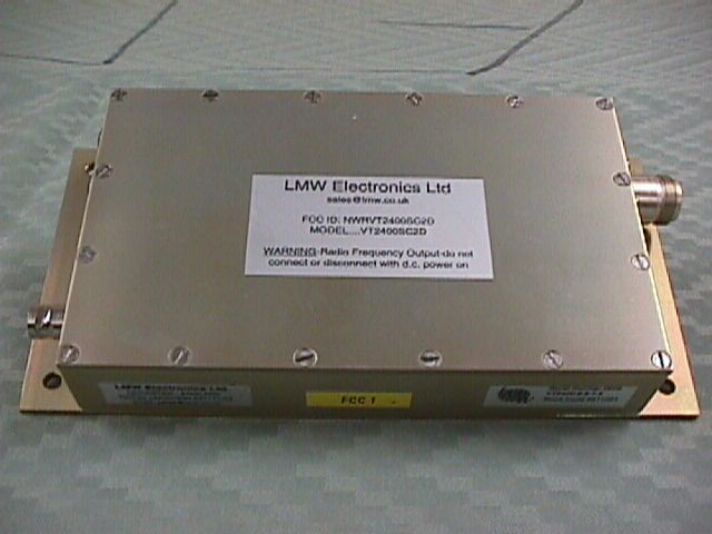
NWRVT2400SC2D
LMW Electronics Ltd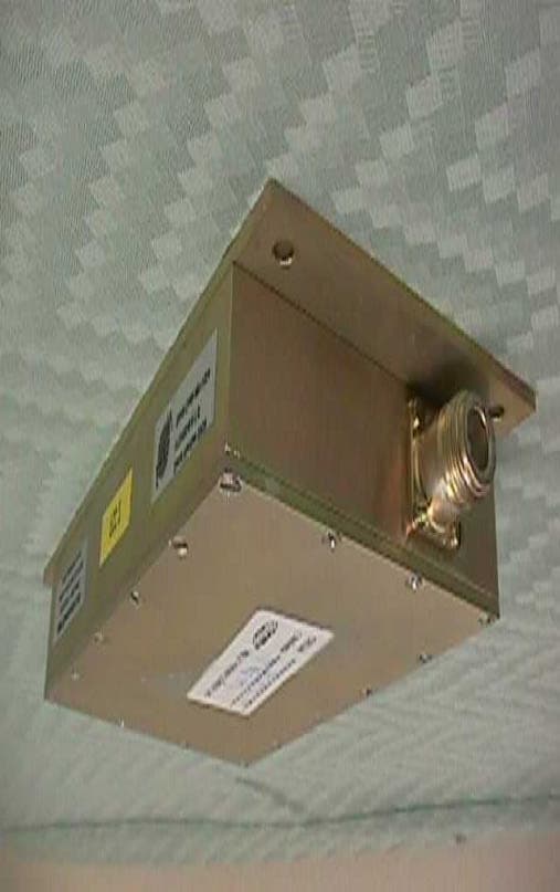
Click to zoom
Application Details
- Equipment Class
- TBC - Licensed Broadcast Station Transmitter
- Date of Grant
- Oct 26, 1999
- Application Purpose
- Original Equipment
- Date of Application
- Aug 15, 1999
- Frequency Range
- 2450.00000000 - 2500.00000000
- Company
- LMW Electronics Ltd
- Country
- United Kingdom
Documents & Files
Document Text
Text extracted from the exhibit documents filed with the FCC. Open a document above to read the original.
Users Manual
VT2400SC2D 1.5W VIDEO TRANSMITTER MODULE F.C.C. I.D. NVRVT2400SC2D END-USER INSTRUCTION MANUAL LMW Electronics Ltd LMW House Leeside Merry Lees Industrial Estate Desford LEICESTER LE9 9FS ENGLAND Tel: +44 (0)1530 231141 Fax: +44 (0)1530 231143 E-Mail: [email protected] Web Page: www.lmw.co.uk L M W 2 CONTENTS 1. INTRODUCTION3 2. VT2400SC2D MULTI-CHANNEL HIGH POWER VIDEO TRANSMITTER4 2.1Connectors4 2.2Use4 2.3Typical connections5 2.3.1Power connections5 2.3.2One Sound Channel Fitted6 2.3.3Twin Sound Channels Fitted7 2.4Specifications7 3. BLOCK DIAGRAM FOR VT2400SC2D VIDEO TRANSMITTER8 4. LIMITED WARRANTY STATEMENT9 5. WARRANTY REGISTRATION DOCUMENT12 3 1. INTRODUCTION Thank you for your purchase of the LMW Model VT2400SC2D 1.5W Video Transmitter Module. The VT2400SC2D is part of a series of innovative low power Video Transmitters that include the VT24SC2D, VT240SC2D and VT2450SC2D Video Transmitters. These small 12V DC Video Transmitter modules can be used for various applications in custom Wireless Video Transmission systems, including Wireless Video Surveillance Systems. These modules are the same as those embedded within the LMW Electronics Ltd., series of Wireless Video Surveillance systems available as turnkey, fully duplex, remote video monitoring equipment. Practical applications for these Video Transmitters range beyond the law enforcement and security communities. They have been employed by the military, in research, by industry, and in a variety of recreational applications both mobile and fixed. LMW Electronics Ltd., of Leicester, England has been the leader in the design and manufacture of rugged and reliable Wireless Video systems for over ten years. LMW Wireless Video Products are guaranteed for one year and are a proven reputation within the Wireless Video world. The End-User Instruction Manual is part of a two manual set that accompanies your VT2400SC2D and provides service details, alignment instruction, schematic drawings and parts listing for this transmitter. Additional service assistance for the VT series of LMW Video Transmitters can be obtained from the closest LMW Electronics Ltd., U.S. Distributor/Representative included on page??? of this manual WARNING: THE SEMICONDUCTORS IN THIS MODULE MAY CONTAIN TOXIC BERYLLIUM OXIDE AND THEREFORE MUST BE HANDLED WITH EXTREME CAUTION. DISPOSAL OF THESE SEMICONDUCTORS MUST BE VIA A SPECIALIST DISPOSAL COMPANY. 4 2. VT2400SC2D MULTI-CHANNEL HIGH POWER VIDEO TRANSMITTER The VT2400SC2D is an S-band (nominally 2.4GHz) video transmitter with nominal 1.5 Watt output, having two audio subcarriers, which will support full colour video applications. The transmitted bandwidth is minimised to give optimum channel performance utilising 725/6 Pre- emphasis curve, with little or no reduction in video bandwidth and performance. The transmitter is housed in a rugged weathersealed, alu-chromed, milled housing with LEMO multipin, BNC and N type connectors. The unit has an extended base plate for panel or wall fixing, or alternatively for installing into the LMW MDR400S Camera Outstation. High and low power outputs can be selected for optimum power efficiency. The transmitter design uses a crystal-referenced, microcontrolled, programmable multi-channel synthesiser, at output frequency for spectral purity, efficiency and linearity. The video processing uses very tight filtering to optimise the channel bandwidth and has power GaAsfet technology in the output stages for efficiency and cleanliness. Audio bandwidth is optimised for high quality audio techniques. 2.1 Connectors PowerLEMO- 4 Pin plug Part No. FGGIB304C Video inputBNC- 75Ω - various Audio - single channel LEMO- 5 Pin Plug Part No. FGGIB305C Audio - dual channelLEMO- 5 pin Plug Part No. FGGIB305C 2.2 Use This transmitter is suited to applications where the best range (several kilometres) is required without drawing excessive DC current combined with a rugged housing which will withstand being out in wet and dusty conditions. All the connectors are water resisting, but some extra protection may be needed for the BNC video cable. Suggested antennas for this unit are the AE03, AE07, AE08 and AE04 (or suitable Directional or Omnidirectional 50Ohm S-Band antenna). The unit has channel change facility built in. To access this, remove the top cover, the one with the label on, and locate the miniature rotary switch. Rotate this selector until the desired channel number is displayed. Replace the lid. 5 To switch to low power, the Hi/Lo is connected to ground (connect BLUE (Pin 1) to 0V), which will reduce the DC input current by approx 300mA, the output power dropping to approx 150mW. The audio inputs are 600Ω balanced or unbalanced. The unit is also designed to bolt straight into the MDR400S camera control outstation. All necessary leads are supplied with the outstation. Figure i: Location of channel change switch on VT2400SC2D 2.3 Typical connections 2.3.1 Power connections FunctionWire ColourPin number GNDBlack2 12VRed4 Hi/Low PowerBlue1 Table i : VT2400SC2D Power Connections Figure ii : 4 Pin LEMO pin out orientation viewed from solder spill (wiring side) side 1 4 3 2 CHANNEL CHANGE SWITCH 6 CAUTION These points should be noted when the VT2400SC2D is used on its own without the MDR400S camera outstation. 1. The Antenna should always be connected before the transmitter is switched on. Also the antenna and interconnecting Coax cable should be of a good VSWR. Always use good low loss cable such as RG400, RG213, RG8, and 9913F, etc. And make sure the connectors are terminated correctly. 2. When the VT2400SC2D is used with a stand alone, 12v DC source. Please select a Power Supply of a suitable standard as to supply a continuous current of 2 Amps, fully regulated, and handle a switch-on current in excess of 5 Amps accurately. Failure to do this will result in an over-voltage surge, causing the internal PCB fuze to blow. A reverse supply is catered for, with a series diode, but caution, any voltage i…
Text truncated - open the document above for the full version.
Operational Description
VT2400SC2D 1.5W VIDEO TRANSMITTER MODULE F.C.C. I.D. NVRVT2400SC2D SERVICE MANUAL LMW Electronics Ltd LMW House Leeside Merry Lees Industrial Estate Desford LEICESTER LE9 9FS ENGLAND Tel: +44 (0)1530 231141 Fax: +44 (0)1530 231143 E-Mail: [email protected] Web Page: www.lmw.co.uk L M W 1 CONTENTS 1. INTRODUCTION2 2. UNIT DESCRIPTION3 2.1The Main Board3 2.2PA Strip3 2.3Audio Board3 SERVICE REPAIR PROCEDURE4 3.1Minimum Test Equipment Requirement4 3.2Visual Inspection4 3.3Preliminary Electrical Check4 3.4Alignment5 4. TYPICAL TEST EQUIPMENT SETUP6 2 1. INTRODUCTION The VT2400SC2D is inherently a reliable and robust unit, however problems may arise and these are mainly due to accidental misuse as follows: - 1) Prolonged use without an antenna connected or with an antenna having a faulty feeder. 2) The 12v DC supply being connected reverse polarised. 3) A DC supply in excess of 16V being applied to the transmitter. Occasionally the misuse may lead to just the 2A fuse being blown. Changing the fuse for one of the same rating is a quick way of proving if there is any further damage to the transmitter. If replacing the fuse does not rectify the fault, then it is likely that as a minimum, the power amplifier FET has suffered catastrophic damage. Replacing the power amplifier FET will in addition require complete re-tuning of the PA strip with the aid of a 12GHz Spectrum Analyser and as such it may be to your advantage to have the transmitter repaired by LMW and returned, working to full specification. We recognise that you may wish to repair the transmitter “in-house” and as such schematics and printed board diagrams are enclosed to facilitate your repair. We must draw your attention to the fact that this will invalidate your Warranty as specified in the End User Instruction Manual. CAUTION These points should be noted when the VT2400SC2D is used on its own without the MDR400S camera outstation. 1. The Antenna should always be connected before the transmitter is switched on. Also the antenna and interconnecting Coax cable should be of a good VSWR. Always use good low loss cable such as RG400, RG213, RG8, and 9913F, etc. And make sure the connectors are terminated correctly. 2. When the VT2400SC2D is used with a stand alone, 12v DC source. Please select a Power Supply of a suitable standard as to supply a continuous current of 2 Amps, fully regulated, and handle a switch-on current in excess of 5 Amps accurately. Failure to do this will result in an over-voltage surge, causing the internal PCB fuze to blow. A reverse supply is catered for, with a series diode, but caution, any voltage in excess of 16V will cause the internal protection circuit to take out the fuze, protecting the more sensitive circuits in the transmitter. Please refer to the Manufacturer or Agent if you are unsure. If the Internal fuze does blow, or the Transmitter fails to give satisfactory results, the unit should be returned to your Agent, or Authorised Service Engineer. 3 2. UNIT DESCRIPTION The Video Transmitter comprises three sub-sections, i.e. the Main Board, PA Strip and Audio Board. 2.1 The Main Board The synthesiser is referenced to a 4MHz Crystal Oscillator and the PROM is “in-factory” programmed with the permitted frequencies or channels. Channel selection is by means of the small BCD switch. A voltage controlled oscillator module (VCO) operating at microwave frequencies is fitted on the underside of the PCB and is fed with the output from the synthesiser to give a highly stable RF output at the channel frequency. The mmic pre-driver and transistor driver amplify the output from the VCO module. Video via the BNC socket is processed by passive component circuitry and fed to the VCO. The resultant deviation may be adjusted by potentiometer R2 but is set at 4MHz deviation for 1V p-p input. Five distinct supply voltages are developed on board, these being, 10V approx., 8.5V approx., -3.5V approx. and 2 off 5V regulated supplies. The negative bias voltage is set by potentiometer R35 to a value of approx. –2.1V. The bias generator circuit incorporates a bias fail safety circuit. 2.2 PA Strip The FET Power Amplifier is fed by matched and tuned lines from the BFG135 Driver. The output is fed via a tuned Low Pass Filter (LPF) to the N socket giving a nominal 1.5W output with low harmonic output. 2.3 Audio Board This PCB is mounted on 2 standoffs and is connected to the main board via a 10-way plug and socket. The audio board contains two independent audio amplifiers, sub-carrier oscillators and modulators feeding a combiner circuit, the output of which goes to the VCO module. Each audio amplifier may, by selecting the connections to the 5-pin Lemo plug, have either balanced or unbalanced inputs. The two sub-carrier oscillators have factory pre-set frequencies which are normally 6.8MHz and 7.5MHz offset from the main carrier. Adjustment of these frequencies is by C31 and C62 respectively. The level of the two sub-carriers is set at 30dB down from the main carrier, adjustment being by R3 and R31 respectively. Audio amplifier circuitry includes pre-emphasis circuits, amplifiers, clipping and filtering circuits the output of which feeds the varicap diode on the sub-carrier circuit. The gain setting potentiometers R9 and R36 determine the deviation for a given input level and frequency, this being pre-set at an unbalanced input of 1V p-p across 600Ω at 1KHz giving a resultant deviation of the sub carrier of 15KHz. 4 3. SERVICE REPAIR PROCEDURE 3.1 Minimum Test Equipment Requirement Digital Voltmeter 0-15V DC Current Meter 0-3A DC DC Power Supply 12.6V at 3A Signal Generator 2.4GHz to 2.5GHz (for calibration purposes) Audio Signal Generator 10KHz @ 380mV and 1KHz @ 332mV. Spectrum Analyser 9KHz to 12.8GHz. Attenuator for Analyser if required. 3.2 Visual Inspection a) Remove 2 x M3 pan-head screws securing the audio board and lay the PCB to one side. b) Check that the 2 jumpers are in place and the prom is secure in its dual in line s…
Text truncated - open the document above for the full version.
Test Report
FCC ID: NWRVT2400SC2D August 9, 1999 Federal Communications Commission Authorization and Evaluation Division 7435 Oakland Mills Road Columbia, MD 21046 Attention:Applications Examiner Applicant:LMW Electronics, Ltd. Marry Lees Industrial Estate. Equipment:Video Transmitter, Model: VT2400SC2D FCC ID: NWRVT2400SC2D Specification:47 CFR Parts 74 & 90 Licensed Certification Dear Examiner: The following application for Grant of Equipment Authorization is presented on behalf of LMW Electronics, Ltd., for the Licensed Certification of their Model:VT2400SC2D, Video Transmitter module. Enclosed, please find a complete data and documentation package demonstrating that this device complies with the technical requirements of 47 CFR, Part 74 and 90, for a Video Transmitter. If you have any questions, please contact the undersigned, who is authorized to act as Agent. Sincerely, Kenneth Bass Sr. EMC Engineer, EMC Laboratory FCC ID: NWRVT2400SC2D MET Laboratories, Inc. Safety Certification - EMI - Telecom Environmental Simulation 914 WEST PATAPSCO AVENUE !! BALTIMORE, MARYLAND 21230-3432 !! PHONE (410) 354-3300 !! FAX (410) 354-3313 ENGINEERING TEST REPORT in support of the Application for Grant of Equipment Authorization EQUIPMENT:Video Transmitter, Model: VT2400SC2D FCC ID:NWRVT2400SC2D Specification:47CFR Parts 74 and 90 On Behalf of the Applicant/LMW Electronics, Inc. Manufacturer:LMW House, Leeside Merry Lees Industrial Estate Desford, LEICESTER LE9 9FS, EngLand Manufacturer’s Mr. Harry Price Representative Test Date(s):May 14 thru June 16, 1999 ENGINEERING STATEMENT I ATTEST: the measurements shown in this report were made in accordance with the procedures indicated, and that the emissions from this equipment were found to be within the limits applicable. I assume full responsibility for the accuracy and completeness of these measurements. On the basis of the measurements made, the equipment tested is capable of operation in accordance with the requirements of Part 74 and 90 of the FCC Rules under normal use and maintenance. _____________________________ Kenneth Bass Sr. EMC Engineer, MET Laboratories, Inc. FCC ID: NWRVT2400SC2D EMI1155A- 3 -August 9, 1999 1.0INTRODUCTION The following data is presented on behalf of the Applicant, LMW Electronics, Inc., as verification of the compliance of the LMW Video Transmitter, Model VT2400SC2D, to the requirements of 47CFR Parts 74 and 90. 2.0TEST SITE All testing was conducted at MET Laboratories, Inc., 914 West Patapsco Avenue, Baltimore, Maryland 21230-3493. Radiated emissions measurements were performed on a three-meter open area test site (OATS). A complete site description is on file with the FCC Laboratory Division as 31040/SIT/MET. 3.0TEST EQUIPMENT USED ManufacturerEquipment Calibration DueCal. Interval Hewlett Packard8563A Spectrum Analyzer05/26/00annual EMCOBiconical Antenna 310402/10/00annual EMCOEMCO Log Periodic Antenna01/04/00annual EMCODouble Ridge Guided Horn05/22/00annual Hewlett Packard8594EM Analyzer11/18/99annual 4.0EQUIPMENT UNDER TEST CONFIGURATION The Video Transmitter was configured with a DC power supply, an NTSC signal generator, and an audio signal generator to produce modulation conditions of the type the EUT was designed to transmit. The EUT was configured for maximum signal gain and bandwidth. In addition, the EUT was operated in a manner representative of the typical usage of the equipment. During all testing, system components were manipulated within the confines of typical usage to maximize each emission. 5.0TEST TYPE(S) 5.1Radiated Emissions: 47CFR2.993, 74.637 (a)(1), (a)(2), and (a)(3); 90.210(b)(1),(b)(2), and (b)(3) 5.2Occupied Bandwidth: 47CFR2.989, 90.209 (bandwidth approved case by case), 74.602(a) ( see table Band A for 2450-2467, and 2467-2483.5 MHz) 5.3Modulation Characteristics : 47CFR 2.987, 74.663 (n/a since FM), and 90.211(a) 5.4RF Power Output: 47CFR 2.985, 90.205(I), and 74.636 5.5Spurious Emission at Antenna Terminals: 47CFR2.991, 90.210 (b)(1),(b)(2), and (b)(3) 74.637(a)(1), (a)(2), and (a)(3). 5.6Frequency Stability over Temperature Variations: 47CFR2.995(a)(1), 74.661, 90.213(a) 5.7Frequency Stability over Voltage Variations: 47CFR2.995(d)(1), 74.661, 90.213(a) E(V/m) 1m ' 49.2X1.56 1 E(V/m) 1m '8.76V/mor138.85dbμV 43%10Log(1.56)'44.93dB 138.85dBμV&44.93dB'93.92dBμV@1m E(V/m) 3m ' 49.2X1.56 3 E(V/m) 3m '2.92V/mor129.31dbμV 129.31&44.93'84.38dBμV@3m FCC ID: NWRVT2400SC2D EMI1155A- 4 -August 9, 1999 6.0TEST RESULTS 6.1TEST TYPE: Radiated Emissions 6.1.1TECHNICAL SPECIFICATION:2.993(a); 90.210(b)(1),(b)(2), and (b)(3); 74.637(a)(1), (a)(2), and (a)(3) 6.1.2TEST DATE(S):June 16, 1999 6.1.3MEASUREMENT PROCEDURES: As required by §2.993, field strength of spurious radiation measurements were made in accordance with the general procedures of ANSI C63.4-1992 "Methods of Measurement of Radio- Noise Emissions from Low-Voltage Electrical and Electronic Equipment in the Range of 9kHz to 40 GHz". Preliminary radiated emission measurements were performed inside a shielded chamber with a digital signal generator on and terminated. The frequency list from the preliminary measurements were used as a guide for making final measurements on an 10 meter open area test site. The unit was scanned over the frequency range of 9 kHz to 24 GHz. The Radiated Spurious Emissions Limit is obtained by the following: Based on an input power (as measured at the output of the Amplifier) of 1.56 watts: P = 1.56 W o As per 2.993 (a), it is assumed this power is to be fed to a half-wave tuned dipole. Using a conversion formula for distance, the field strength at one meter can be derived: As per 90.210(b)(3) and 74.637(a)(3), spurious emissions must be attenuated by 43 + log(P), which is: Therefore, the limit for spurious emissions is: At 3 meters measurement distance, the limit is; Again, according to the above applicable rule parts, all signals must be attenuated by 44.93dB; Therefore, the limit for spurious emissions for a test distance of…
Text truncated - open the document above for the full version.
Contact Information
Applicant
C. M. Smith(Managing Director)
44-(0)1530231141Fax: 44(0)1530231143
Technical Contact
MET Laboratories, Inc.Ken Bass
[email protected](410)354-3300
914 West Patapsco Ave. · Baltimore, Maryland · United States
Non-Technical Contact
MET Laboratories, Inc.Terri Wolf
[email protected](410) 354-3300
Test Firm
MET Laboratories, Inc.John Mason
Technical Specifications
| # | Rule Parts | Frequency Range | Power Output | Emission | Tolerance |
|---|---|---|---|---|---|
| 1 | 74,90 | 2.45 GHz - 2.50 GHz | 1.5 W | 17M0F8W | 0.0015000000 % |