NYYH300Notebook Computer
Movita Technologies Inc.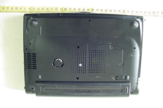
Click to zoom
Application Details
- Equipment Class
- JBC - Part 15 Class B Computing Device/Personal Computer
- Date of Grant
- Feb 06, 2003
- Application Purpose
- Original Equipment
- Date of Application
- Feb 06, 2003
- Equipment Note
- Notebook Computer
- Company
- Movita Technologies Inc.
- Country
- Taiwan
Documents & Files
Document Text
Text extracted from the exhibit documents filed with the FCC. Open a document above to read the original.
Users Manual
Table Of Contents Chapter 1Introduction.................................................1-1 Welcome.......................................................................................1-1 To Open the Notebook......................................................................1-1 Taking a look at this Notebook............................................................1-2 Front View....................................................................................1-2 Left View......................................................................................1-3 Right View....................................................................................1-4 Rear View....................................................................................1-4 Bottom View.................................................................................1-5 Chapter 2Operating The Notebook...............................2-1 Getting the Computer Running...........................................................2-1 Connecting Power to the System......................................................2-1 Turning On and Off the Computer.....................................................2-2 About Power Indicators.....................................................................2-3 About the Status Indicators................................................................2-3 About the Keyboard..........................................................................2-4 Using the Touch pad........................................................................2-5 About a Security Lock (Kensington Lock)..............................................2-5 Using the Video Features..................................................................2-5 Settings........................................................................................2-5 Setting the External Monitor.............................................................2-6 Using the Audio Features..................................................................2-6 Sound Ports..................................................................................2-6 Using the Communication Features.....................................................2-7 Using the LAN...............................................................................2-7 Using the Modem...........................................................................2-7 Using the Optical Drive.....................................................................2-8 Connecting the external optical Drive.................................................2-8 Inserting and removing a CD............................................................2-8 Using the Floppy Disk Drive...............................................................2-9 Using the Hard Disk Drive..................................................................2-9 Using the Utility CD........................................................................2-10 Chapter 3Power Management......................................3-1 About the AC Adapter.......................................................................3-1 Using the Battery Pack.....................................................................3-2 To Change the Battery Pack............................................................3-2 Battery Charging............................................................................3-2 Battery Discharging........................................................................3-2 Battery Low Warnings.....................................................................3-3 Using Power Management.................................................................3-3 Standby Mode...............................................................................3-3 Hibernate Mode.............................................................................3-3 Initiating Standby or Hibernate Mode..................................................3-4 Chapter 5: Expanding The Notebook...............................5-1 Using PC Cards..............................................................................5-1 PC Card Type...............................................................................5-1 CardBus Support...........................................................................5-1 Inserting and Removing a PC Card....................................................5-1 Connecting a USB 2.0 Device............................................................5-3 Connecting an External Monitor..........................................................5-3 Internal Components Upgrade............................................................5-4 Notice: The changes or modifications not expressly approved by the party responsible for compliance could void the user’s authority to operate the equipment. Federal Communications Commission (FCC) - Notebook The Federal Communication Commission Radio Frequency Interference Statement includes the following paragraph: This equipment has been tested and found to comply with the limits for a Class B digital device, pursuant to Part 15 of the FCC Rules. These limits are designed to provide reasonable protection against harmful interference in a residential installation. This equipment generates, uses, and can radiate radio frequency energy and, if not installed and used in accordance with the instructions, may cause harmful interference to radio communications. However there is no guarantee that interference will not occur in a particular installation. If this equipment does cause harmful interference to radio or television reception, which can be determined by turning the equipment off and on, the user is encouraged to try to correct the interference by one or more of the following measures: q Reorient or relocate the receiving antenna. q Increase the separation between the equipment and the receiver. q Connect the equipment into an outlet on a circuit different from that to w…
Text truncated - open the document above for the full version.
External Photos
ETC Report No.:ET91R-11-032-01 Sheet 1 of 25 Sheets FCC ID. : NYYH300 Rev. No 1.0 CONSTRUCTED PHOTOS of EUT 1. Top View of EUT 2. Side View of EUT ETC Report No.:ET91R-11-032-01 Sheet 2 of 25 Sheets FCC ID. : NYYH300 Rev. No 1.0 CONSTRUCTED PHOTOS of EUT 3. Side View of EUT 4. Bottom View of EUT ETC Report No.:ET91R-11-032-01 Sheet 3 of 25 Sheets FCC ID. : NYYH300 Rev. No 1.0 CONSTRUCTED PHOTOS of EUT 5. Open View of EUT
Internal Photos
ETC Report No.:ET91R-11-032-01 Sheet 3 of 25 Sheets FCC ID. : NYYH300 Rev. No 1.0 CONSTRUCTED PHOTOS of EUT 6. Internal View of EUT ETC Report No.:ET91R-11-032-01 Sheet 4 of 25 Sheets FCC ID. : NYYH300 Rev. No 1.0 CONSTRUCTED PHOTOS of EUT 7. Internal View of EUT 8. Internal View of EUT ETC Report No.:ET91R-11-032-01 Sheet 5 of 25 Sheets FCC ID. : NYYH300 Rev. No 1.0 CONSTRUCTED PHOTOS of EUT 9. Internal View of EUT 10. Internal View of EUT ETC Report No.:ET91R-11-032-01 Sheet 6 of 25 Sheets FCC ID. : NYYH300 Rev. No 1.0 CONSTRUCTED PHOTOS of EUT 11. Internal View of EUT 12. Internal View of EUT ETC Report No.:ET91R-11-032-01 Sheet 7 of 25 Sheets FCC ID. : NYYH300 Rev. No 1.0 CONSTRUCTED PHOTOS of EUT 13. Total View of PCB 14. Total View of PCB ETC Report No.:ET91R-11-032-01 Sheet 8 of 25 Sheets FCC ID. : NYYH300 Rev. No 1.0 CONSTRUCTED PHOTOS of EUT 15. Total View of PCB 16. Front View of PCB ETC Report No.:ET91R-11-032-01 Sheet 9 of 25 Sheets FCC ID. : NYYH300 Rev. No 1.0 CONSTRUCTED PHOTOS of EUT 17. Front View of PCB 1 18. Rear View of PCB 1 ETC Report No.:ET91R-11-032-01 Sheet 10 of 25 Sheets FCC ID. : NYYH300 Rev. No 1.0 CONSTRUCTED PHOTOS of EUT 19. Component View of PCB 2 20. Solder View of PCB 2 ETC Report No.:ET91R-11-032-01 Sheet 11 of 25 Sheets FCC ID. : NYYH300 Rev. No 1.0 CONSTRUCTED PHOTOS of EUT 21. Component View of PCB 3 22. Solder View of PCB 4 ETC Report No.:ET91R-11-032-01 Sheet 12 of 25 Sheets FCC ID. : NYYH300 Rev. No 1.0 CONSTRUCTED PHOTOS of EUT 23. Component View of PCB 5 24. Solder View of PCB 5 ETC Report No.:ET91R-11-032-01 Sheet 13 of 25 Sheets FCC ID. : NYYH300 Rev. No 1.0 CONSTRUCTED PHOTOS of EUT 25. Component View of PCB 6 26. Solder View of PCB 6 ETC Report No.:ET91R-11-032-01 Sheet 14 of 25 Sheets FCC ID. : NYYH300 Rev. No 1.0 CONSTRUCTED PHOTOS of EUT 27. Component View of LCD Panel 28. Component View of LCD Panel
Internal Photos
ETC Report No.:ET91R-11-032-01 Sheet 15 of 25 Sheets FCC ID. : NYYH300 Rev. No 1.0 CONSTRUCTED PHOTOS of EUT 29. Solder View of LCD Panel 30. Solder View of LCD Panel ETC Report No.:ET91R-11-032-01 Sheet 16 of 25 Sheets FCC ID. : NYYH300 Rev. No 1.0 CONSTRUCTED PHOTOS of EUT 31. Front View of Hard Disk Drive 32. Front View of Hard Disk Drive ETC Report No.:ET91R-11-032-01 Sheet 17 of 25 Sheets FCC ID. : NYYH300 Rev. No 1.0 CONSTRUCTED PHOTOS of EUT 33. Rear View Hard Disk Drive 34. Front View of Battery ETC Report No.:ET91R-11-032-01 Sheet 18 of 25 Sheets FCC ID. : NYYH300 Rev. No 1.0 CONSTRUCTED PHOTOS of EUT 35. Rear View of Battery 36. Top View of Adaptor I ETC Report No.:ET91R-11-032-01 Sheet 19 of 25 Sheets FCC ID. : NYYH300 Rev. No 1.0 CONSTRUCTED PHOTOS of EUT 37. Front View of Adatpor I 38. Rear View of Adaptor I ETC Report No.:ET91R-11-032-01 Sheet 20 of 25 Sheets FCC ID. : NYYH300 Rev. No 1.0 CONSTRUCTED PHOTOS of EUT 39. Bottom View of Adaptor I 40. Internal View of Adaptor I ETC Report No.:ET91R-11-032-01 Sheet 21 of 25 Sheets FCC ID. : NYYH300 Rev. No 1.0 CONSTRUCTED PHOTOS of EUT 41. Component View of Adaptor PCB 42. Solder View of Adaptor PCB ETC Report No.:ET91R-11-032-01 Sheet 22 of 25 Sheets FCC ID. : NYYH300 Rev. No 1.0 CONSTRUCTED PHOTOS of EUT 43. Top View of Adaptor II 44. Front View of Adaptor II ETC Report No.:ET91R-11-032-01 Sheet 23 of 25 Sheets FCC ID. : NYYH300 Rev. No 1.0 CONSTRUCTED PHOTOS of EUT 45. Rear View of Adaptor II 46. Bottom View of Adaptor II ETC Report No.:ET91R-11-032-01 Sheet 24 of 25 Sheets FCC ID. : NYYH300 Rev. No 1.0 CONSTRUCTED PHOTOS of EUT 47. Internal View of Adaptor II 48. Component View of Adaptor PCB ETC Report No.:ET91R-11-032-01 Sheet 25 of 25 Sheets FCC ID. : NYYH300 Rev. No 1.0 CONSTRUCTED PHOTOS of EUT 49. Solder View of Adaptor PCB ETC Report No.:ET91R-11-032-01 Sheet 25-1 of 25-1 Sheets FCC ID. : NYYH300 Rev. No 1.0 CONSTRUCTED PHOTOS of EUT 50. Component View of PCB 51. Solder View of PCB
Test Report
Rev. No 1.0 FCC PART 15 EMI TEST REPORT of E.U.T. : notebook computer MODEL : H300 TYPE NO. : H330 FCC ID. : NYYH300 for APPLICANT : MOVITA TECHNOLOGIES INC. ADDRESS : No. 26, Wu-Chuan 7th Rd., Wu-Ku Industrial Park, Taipei County, Taiwan, R.O.C. Test Performed by ELECTRONICS TESTING CENTER, TAIWAN NO. 34, LIN 5, DING FU TSUN, LINKOU HSIANG TAIPEI HSIEN, TAIWAN, R.O.C. Tel:(02)26023052, 26023054 Fax:(02)26010910 Report Number : ET91R-11-032-01 ETC Report No. : ET91R-11-032-01 FCC ID. : NYYH300 Rev. No 1.0 TEST REPORT VERIFICATION Applicant : MOVITA TECHNOLOGIES INC. No. 26, Wu-Chuan 7th Rd., Wu-Ku Industrial Park, Taipei County, Taiwan, R.O.C. Manufacturer : MOVITA TECHNOLOGIES INC. No. 26, Wu-Chuan 7th Rd., Wu-Ku Industrial Park, Taipei County, Taiwan, R.O.C. Description of EUT : a) Type of EUT : notebook computer b) Trade Name : MOVITAMUSTEK c) Model No. : H300 d) Type No. : H330 e) Power Supply : Adaptor 1MHASV08IA I/P:100~240VAC, 1.5A,50/60Hz; O/P:16VDC, 3.12A Adaptor 2LSE9802A1650 I/P:100~240VAC, 1.5A,50/60Hz; O/P:16VDC, 3.13A Regulation Applied : FCC Rules and Regulations Part 15 Subpart B (2002) I HEREBY CERTIFY THAT: The data shown in this report were made in accordance with the procedures given in ANSI C63.4, and the energy emitted by the device was founded to be within the limits applicable. I assume full responsibility for accuracy and completeness of these data. Note: 1. The result of the testing report relate only to the item tested. 2. The testing report shall not be reproduced expect in full, without the written approval of ETC. Issued Date: Dec. 20, 2002 Test Engineer: ( Ion Lin ) Approve & Authorized Signer: Will Yauo, Manager EMC Dept. II of ELECTRONICS TESTING CENTER, TAIWAN ETC Report No. : ET91R-11-032-01 FCC ID. : NYYH300 Rev. No 1.0 Table of Contents Page 1 GENERAL INFORMATION.......................................................................................................1 1.1 Product Description...................................................................................................................1 1.2 Characteristics of Device..........................................................................................................1 1.3 Test Methodology.......................................................................................................................2 1.4 Test Facility................................................................................................................................2 2 LIMITATIONS AND LABELING REQUIREMENT...............................................................3 2.1 Definition....................................................................................................................................3 2.2 Limitation...................................................................................................................................4 2.3 Labeling Requirement................................................................................................................4 2.4 User Information........................................................................................................................5 3 SYSTEM TEST CONFIGURATION..........................................................................................6 3.1 Justification................................................................................................................................6 3.2 Device for Tested System.........................................................................................................6 4 RADIATED EMISSION MEASUREMENT..............................................................................7 4.1 Description for Radiated Emission Measured........................................................................7 4.2 Radiated Emission Data.............................................................................................................8 4.3 Field Strength Calculation.......................................................................................................10 4.4 Equipment for Radiation Measurement.................................................................................11 4.5 Measuring Instrument Setup....................................................................................................11 4.6 Photos of Radiation Measuring Setup....................................................................................12 4.7 Open Field Test Site Setup Diagram.......................................................................................14 5 CONDUCTED EMISSION MEASUREMENT........................................................................15 5.1 Standard Applicable..................................................................................................................15 5.2 Measurement Procedure.........................................................................................................15 5.3 Conducted Emission Data.......................................................................................................16 5.4 Result Data Calculation...........................................................................................................17 5.5 Conducted Measurement Equipment......................................................................................17 5.6 Photos of Conduction Measuring Setup................................................................................18 APPENDIX 1 : PLOTTED DATA FOR CONDUCTED EMISSION..........................................20 ETC Report No.:ET91R-11-032-01 Sheet 1 of 20 Sheets FCC ID. : NYYH300 Rev. No 1.0 1 GENERAL INFORMATION 1.1 Product Description a) Type of EUT : notebook computer b) Trade Name : MOVITAMUSTEK c) Model No. : H300 d) Type No. : H330 e) Power Supply : Adaptor 1 HASV08IA I/P:100~240VAC, 1.5A,50/60Hz; O/P:16VDC, 3.12A Adaptor 2 LSE9802A1650 I/P:100~240VAC, 1.5A,50/60Hz; O/P:16VDC, 3.13A 1.2 Characteristics of Device 1.…
Text truncated - open the document above for the full version.
Test Setup Photos
ETC Report No.:ET91R-11-032-01 Sheet 12 of 20 Sheets FCC ID. : NYYH300 Rev. No 1.0 4.6 Photos of Radiation Measuring Setup A. Adaptor 1 ETC Report No.:ET91R-11-032-01 Sheet 13 of 20 Sheets FCC ID. : NYYH300 Rev. No 1.0 B. Adaptor 2 ETC Report No.:ET91R-11-032-01 Sheet 18 of 20 Sheets FCC ID. : NYYH300 Rev. No 1.0 5.6 Photos of Conduction Measuring Setup A. Adaptor 1 ETC Report No.:ET91R-11-032-01 Sheet 19 of 20 Sheets FCC ID. : NYYH300 Rev. No 1.0 B. Adaptor 2
Contact Information
Applicant
Howard Shi(Manager)
886-2-2290-1060Fax: 886-2-2299-0920
Test Firm
Electronics Testing Center, TaiwanWill Yauo
Technical Specifications
| # | Rule Parts | Frequency Range | Power Output |
|---|---|---|---|
| 1 | 15B | - | - |
Other Applications from Movita Technologies Inc.

NYYODX-100
Feb 04, 2003External USB Combo Drive
Equipment Class
JBP - Part 15 Class B Computing Device Peripheral
NYYOD-100
Jan 07, 2003External USB 2.0 Optical Drive
Equipment Class
JBP - Part 15 Class B Computing Device Peripheral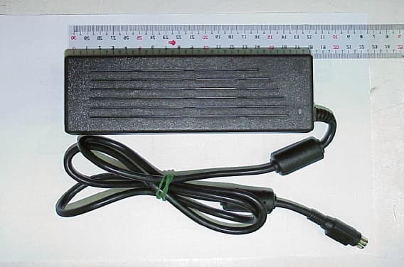
NYYB750
May 07, 2002Notebook Computer
Equipment Class
JBC - Part 15 Class B Computing Device/Personal Computer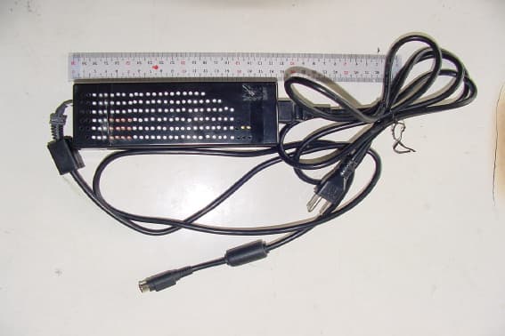
NYY270
May 07, 2002Notebook Computer
Equipment Class
JBC - Part 15 Class B Computing Device/Personal Computer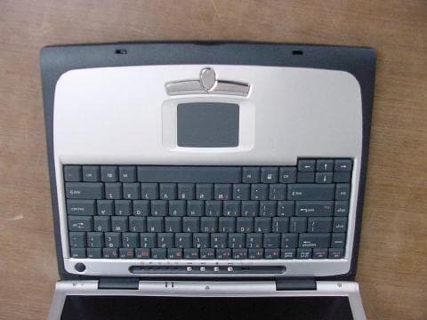
NYYC600
Sep 25, 2001Notebook PC
Equipment Class
JBC - Part 15 Class B Computing Device/Personal Computer