NZ6T8130CWIRELESS IP ( CDPD) MODEM FOR OEMs
Tellus Technology Inc.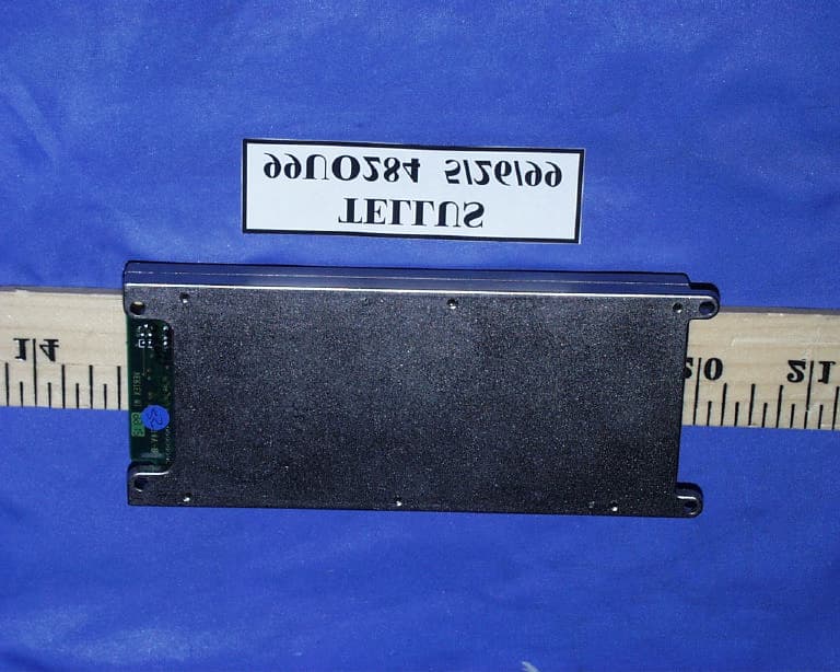
Click to zoom
Application Details
- Equipment Class
- TNB - Licensed Non-Broadcast Station Transmitter
- Date of Grant
- Dec 09, 1999
- Application Purpose
- Original Equipment
- Date of Application
- Jun 09, 1999
- Equipment Note
- WIRELESS IP ( CDPD) MODEM FOR OEMs
- Frequency Range
- 824.00000000 - 849.00000000
- Company
- Tellus Technology Inc.
- Country
- United States
Documents & Files
Document Text
Text extracted from the exhibit documents filed with the FCC. Open a document above to read the original.
Users Manual
Tellus Technology, Inc. Steps in setting up TPRM dial-up networking and connection 1. Connection - Connect the Flex cable from TPRM connector to Transceiver board connector. - Plug in the antenna cable at TPRM antenna connector and install the antenna at other end of SMA-male type. - Connect the DB-9 serial cable between the PC and the Transceiver. - Plug the 7.5 VAC adaptor into the transceiver board. Make the power LED is on. 2. Add new modem to control panel Go to the modems icon in the Windows Control Panel, and click “Add” to install a new modem. Note: Do not let windows detect your modem. With no modems connected to the computer, the screen will eventual allow selection of a standard modem. Select "standard 28800 modem" under “Standard modem types” manufacturers, as new the modem to install, then type “Next”, then select COM1 for the Communications Port. Setup the following modem properties for the newly created Standard 28800 bps Modem baud rate 38400 8 data bits no parity 1 stop bit use hardware flow control 3. Add new dial-up networking named "Tellus-TPRM" Change the properties of the newly created dial-up networking: In "Connect using", select "standard 28800 modem" which you have just created. In "Server Types" select "SLIP: Unix Connection" and make sure that “Log on to Network” is not checked. In "Allowed network protocol" select "TCP/IP" In the sub-menu "TCP/IP Settings", specify the correct modem IP address and name server IP addresses. 4. Uninstall the current version of Monarch Advisor, and install the new version (v1.06) from the floppy provided for usage with the standard Monarchs. This is for installing the Monarch modem, so a Monarch modem must be available during the install. This will create a dial up connection called “Tellus Monarch”. To use Advisor and dial-up networking for TPRM, also do the following: Copy AdvisorTPRM.exe from the floppy to C:\Program Files\Tellus\Monarch Advisor. Run the AdvisorTPRM for usage with the TPRM units.
Users Manual
ProductSpec.doc TPRM Product Specification V1.13 22 September, 1999 1998and 1999 by: TeLLUS Technology, Inc. 40990 Encyclopedia Circle Fremont, CA 94538-2470 USA For information, please contact: Technical Support Tel:+1 510 498 8500 Fax:+1 510 498 8540 The content of this document is subject to change without notice TPRMProductSpec.docProprietary InformationTellus Technology, Inc. 2 of 9 Table of Contents 1.Introduction.................................................................................................2 2.Hardware Interface......................................................................................2 3.Software Interface.......................................................................................6 4.Operation Procedures.................................................................................6 1.1Protocol Synchronization..............................................................................................6 1.2Modem Configuration...................................................................................................6 1.3Modem Connection Procedure......................................................................................6 1.4Status Monitor and System Configuration Procedure....................................................7 1.5Protocol Re-Synchronization Procedure........................................................................7 5.Mechanical Specification.............................................................................7 6.FCC Requirements......................................................................................7 1. Introduction This document describes the specification of a CDPD module, which is designed for system integrators that require a CDPD modem. Section 2 describes the hardware interface for this module. The module has a serial interface connector for the Host to communicate with. An antenna connector is also provided for connecting to an external antenna. A standard 50Ω dipole antenna is suggested. The software specification are referenced in Section 3. For a detailed description, refer to referenced documents containing the specifications. Some operation procedures are given in Section 4. These procedures should be treated as examples for the Host firmware developer. The mechanical specification is given in Section 5. FCC Requirements are provided in Section 6. 2. Hardware Interface In this section, we describe the external interface of the CDPD modem module. The hardware interface has two parts: the antenna connector and the baseband signal connector. The antenna connection is a standard MMCX 50Ω connector. A 50Ω co-axial cable is required to connect to the external antenna. A standard 50Ω dipole antenna is recommended. TPRMProductSpec.docProprietary InformationTellus Technology, Inc. 3 of 9 The baseband serial connector is an SMT ZIF Connector, 12 Pin, FH10-12S-1SH Hirose (53-152310-02TEKCON) which accepts a I mm Flex Cable. Host Interface An asynchronous serial interface to the Host is implemented to support the communications and data transfer between the modem and the Host. A 12-pin connector is used to implement this serial interface. The Host should set up the serial communication line control to match with the modem’s communication line setup. The parameters, which must be set, include the baud rate, number of data bits, parity, and number of stop bits. The modem parameters are 38400 baud, 8 data bits, no parity, and 1 stop bit (or more concisely, 38400 8-N-1). The pin assignment is shown in the connector pin out table below. Take extra precaution to ensure that pin 1 of the mating connector connects to pin 1 of the board connector. When looking into the connector on the TPRM unit, pin 1 is on the far right. Also ensure that the contacts on the connector cable mate to the contacts on the connector. The connector contacts for the TPRM are on the top, when looking into the connector. TPRMProductSpec.docProprietary InformationTellus Technology, Inc. 4 of 9 Connector Pin Out Table Pin NumberPin Name 1PWR 2PWR 3GND 4TXD 5RXD 6/CTS 7/RTS 8GND 9TX_IND 10RSSI 11RESET 12Reserved Pin Descriptions The following table describes the function of each of the connector pins. In the following descriptions, a CMOS logic low or logic 0 is < 0.8V and a CMOS logic high or logic 1 is > 4.0V. Pin NamePin #I/OPin Description PWR1 and 2I +5VDC ± 0.15V power input. 50mV peak-to-peak ripple. The current requirement is 720mA max. The connector is rated at 0.5 A, hence the use of two pins for power. GND3 and 8N/AGround TXD4OSerial data transmit output. This is a CMOS output. RXD5ISerial data receive input. This is a CMOS input. TPRMProductSpec.docProprietary InformationTellus Technology, Inc. 5 of 9 /CTS6OClear to send output from the modem A logic low indicates that the modem is able to accept data. A logic high indicates that the modem is not able to accept data and therefore the host should not send any data. If data is sent while this output is high, the data will not be received correctly by the modem. This is a CMOS output. /RTS7IReady to send input from the host A logic low indicates that the host is able to accept data. A logic high indicates that the host is not able to accept data; therefore, the modem should not send any data. If data is sent while this input is high, the data may not be received correctly by the host. This is a CMOS input. TX_IND9OTransmit indication This CMOS output goes logic high when the modem is transmitting RSSI10OReceived signal strength This CMOS output must see a high impedance load. It provides an indication of received signal level. For basic indication, route to the base of a transistor through a 10K resistor with the emitter grounded. When the transistor collector sinks current, then RF signal is being received. RESET11IReset input This is a CMOS input, providing a hardware reset to the modem. Set to a logic high to reset the modem. The pulse width must be…
Text truncated - open the document above for the full version.
Users Manual
TPRM ProductSpec.doc TPRM Product Specification V1.14 29 September, 1999 1998and 1999 by: TeLLUS Technology, Inc. 40990 Encyclopedia Circle Fremont, CA 94538-2470 USA For information, please contact: Technical Support Tel:+1 510 498 8500 Fax:+1 510 498 8540 The content of this document is subject to change without notice TPRMTPRM ProductSpec.docProprietary InformationTellus Technology, Inc. i Table of Contents 1.Introduction .................................................................................................1 2.Hardware Interface......................................................................................1 3.Software Interface.......................................................................................4 4.Operation Procedures.................................................................................4 1.1Protocol Synchronization..............................................................................................4 1.2Modem Configuration...................................................................................................4 1.3Modem Connection Procedure......................................................................................4 1.4Status Monitor and System Configuration Procedure....................................................5 1.5Protocol Re-Synchronization Procedure........................................................................5 5.Mechanical Specification.............................................................................5 6.FCC Requirements......................................................................................5 TPRM ProductSpec.doc 1 of 7 1. Introduction This document describes the specification of a CDPD module, which is designed for system integrators that require a CDPD modem. Section 2 describes the hardware interface for this module. The module has a serial interface connector for the Host to communicate with. An antenna connector is also provided for connecting to an external antenna. A standard 50Ω dipole antenna is suggested. The software specification are referenced in Section 3. For a detailed description, refer to referenced documents containing the specifications. Some operation procedures are given in Section 4. These procedures should be treated as examples for the Host firmware developer. The mechanical specification is given in Section 5. FCC Requirements are provided in Section 6. 2. Hardware Interface In this section, we describe the external interface of the CDPD modem module. The hardware interface has two parts: the antenna connector and the baseband signal connector. The antenna connection is a standard MMCX 50Ω connector. A 50Ω co-axial cable is required to connect to the external antenna. A standard 50Ω dipole antenna is recommended. The baseband serial connector is an SMT ZIF Connector, 12 Pin, FH10-12S-1SH Hirose (53-152310-02TEKCON) which accepts a I mm Flex Cable. Host Interface An asynchronous serial interface to the Host is implemented to support the communications and data transfer between the modem and the Host. A 12-pin connector is used to implement this serial interface. The Host should set up the serial communication line control to match with the modem’s communication line setup. The parameters, which must be set, include the baud rate, number of data bits, parity, and number of stop bits. The modem parameters are 38400 baud, 8 data bits, no parity, and 1 stop bit (or more concisely, 38400 8-N-1). The pin assignment is shown in the connector pin out table below. Take extra precaution to ensure that pin 1 of the mating connector connects to pin 1 of the board connector. When looking into the connector on the TPRM unit, pin 1 is on the far right. Also ensure that the contacts on the connector cable mate to the contacts on the connector. The connector contacts for the TPRM are on the top, when looking into the connector. TPRMTPRM ProductSpec.docProprietary InformationTellus Technology, Inc. 2 of 7 Connector Pin Out Table Pin NumberPin Name 1PWR 2PWR 3GND 4TXD 5RXD 6/CTS 7/RTS 8GND 9TX_IND 10RSSI 11RESET 12Reserved Pin Descriptions The following table describes the function of each of the connector pins. In the following descriptions, a CMOS logic low or logic 0 is < 0.8V and a CMOS logic high or logic 1 is > 4.0V. Pin NamePin #I/OPin Description PWR1 and 2I +5VDC ± 0.15V power input. 50mV peak-to-peak ripple. The current requirement is 720mA max. The connector is rated at 0.5 A, hence the use of two pins for power. GND3 and 8N/AGround TXD4OSerial data transmit output. This is a CMOS output. RXD5ISerial data receive input. This is a CMOS input. TPRMTPRM ProductSpec.docProprietary InformationTellus Technology, Inc. 3 of 7 /CTS6OClear to send output from the modem A logic low indicates that the modem is able to accept data. A logic high indicates that the modem is not able to accept data and therefore the host should not send any data. If data is sent while this output is high, the data will not be received correctly by the modem. This is a CMOS output. /RTS7IReady to send input from the host A logic low indicates that the host is able to accept data. A logic high indicates that the host is not able to accept data; therefore, the modem should not send any data. If data is sent while this input is high, the data may not be received correctly by the host. This is a CMOS input. TX_IND9OTransmit indication This CMOS output goes logic high when the modem is transmitting RSSI10OReceived signal strength This CMOS output must see a high impedance load. It provides an indication of received signal level. For basic indication, route to the base of a transistor through a 10K resistor with the emitter grounded. When the transistor collector sinks current, then RF signal is being received. RESET11IReset input This is a CMOS input, providing a hardware reset to the modem. Set to a logic high to reset the modem. The pulse width must be at least 1us in duration. Re…
Text truncated - open the document above for the full version.
Users Manual
TPRM ProductSpec.doc TPRM Product Specification V1.14 29 September, 1999 1998and 1999 by: TeLLUS Technology, Inc. 40990 Encyclopedia Circle Fremont, CA 94538-2470 USA For information, please contact: Technical Support Tel:+1 510 498 8500 Fax:+1 510 498 8540 The content of this document is subject to change without notice TPRMTPRM ProductSpec.docProprietary InformationTellus Technology, Inc. i Table of Contents 1.Introduction .................................................................................................1 2.Hardware Interface......................................................................................1 3.Software Interface.......................................................................................4 4.Operation Procedures.................................................................................4 1.1Protocol Synchronization..............................................................................................4 1.2Modem Configuration...................................................................................................4 1.3Modem Connection Procedure......................................................................................4 1.4Status Monitor and System Configuration Procedure....................................................5 1.5Protocol Re-Synchronization Procedure........................................................................5 5.Mechanical Specification.............................................................................5 6.FCC Requirements......................................................................................5 TPRM ProductSpec.doc 1 of 7 1. Introduction This document describes the specification of a CDPD module, which is designed for system integrators that require a CDPD modem. Section 2 describes the hardware interface for this module. The module has a serial interface connector for the Host to communicate with. An antenna connector is also provided for connecting to an external antenna. A standard 50Ω dipole antenna is suggested. The software specification are referenced in Section 3. For a detailed description, refer to referenced documents containing the specifications. Some operation procedures are given in Section 4. These procedures should be treated as examples for the Host firmware developer. The mechanical specification is given in Section 5. FCC Requirements are provided in Section 6. 2. Hardware Interface In this section, we describe the external interface of the CDPD modem module. The hardware interface has two parts: the antenna connector and the baseband signal connector. The antenna connection is a standard MMCX 50Ω connector. A 50Ω co-axial cable is required to connect to the external antenna. A standard 50Ω dipole antenna is recommended. The baseband serial connector is an SMT ZIF Connector, 12 Pin, FH10-12S-1SH Hirose (53-152310-02TEKCON) which accepts a I mm Flex Cable. Host Interface An asynchronous serial interface to the Host is implemented to support the communications and data transfer between the modem and the Host. A 12-pin connector is used to implement this serial interface. The Host should set up the serial communication line control to match with the modem’s communication line setup. The parameters, which must be set, include the baud rate, number of data bits, parity, and number of stop bits. The modem parameters are 38400 baud, 8 data bits, no parity, and 1 stop bit (or more concisely, 38400 8-N-1). The pin assignment is shown in the connector pin out table below. Take extra precaution to ensure that pin 1 of the mating connector connects to pin 1 of the board connector. When looking into the connector on the TPRM unit, pin 1 is on the far right. Also ensure that the contacts on the connector cable mate to the contacts on the connector. The connector contacts for the TPRM are on the top, when looking into the connector. TPRMTPRM ProductSpec.docProprietary InformationTellus Technology, Inc. 2 of 7 Connector Pin Out Table Pin NumberPin Name 1PWR 2PWR 3GND 4TXD 5RXD 6/CTS 7/RTS 8GND 9TX_IND 10RSSI 11RESET 12Reserved Pin Descriptions The following table describes the function of each of the connector pins. In the following descriptions, a CMOS logic low or logic 0 is < 0.8V and a CMOS logic high or logic 1 is > 4.0V. Pin NamePin #I/OPin Description PWR1 and 2I +5VDC ± 0.15V power input. 50mV peak-to-peak ripple. The current requirement is 720mA max. The connector is rated at 0.5 A, hence the use of two pins for power. GND3 and 8N/AGround TXD4OSerial data transmit output. This is a CMOS output. RXD5ISerial data receive input. This is a CMOS input. TPRMTPRM ProductSpec.docProprietary InformationTellus Technology, Inc. 3 of 7 /CTS6OClear to send output from the modem A logic low indicates that the modem is able to accept data. A logic high indicates that the modem is not able to accept data and therefore the host should not send any data. If data is sent while this output is high, the data will not be received correctly by the modem. This is a CMOS output. /RTS7IReady to send input from the host A logic low indicates that the host is able to accept data. A logic high indicates that the host is not able to accept data; therefore, the modem should not send any data. If data is sent while this input is high, the data may not be received correctly by the host. This is a CMOS input. TX_IND9OTransmit indication This CMOS output goes logic high when the modem is transmitting RSSI10OReceived signal strength This CMOS output must see a high impedance load. It provides an indication of received signal level. For basic indication, route to the base of a transistor through a 10K resistor with the emitter grounded. When the transistor collector sinks current, then RF signal is being received. RESET11IReset input This is a CMOS input, providing a hardware reset to the modem. Set to a logic high to reset the modem. The pulse width must be at least 1us in duration. Re…
Text truncated - open the document above for the full version.
Block Diagram
Tellus Technology, Inc. CDPD Wireless Modem RF Block Diagram ANTENNA DIELECTRIC FILTER DUPLEXER LNA Rx: 869 - 894 MHz SAW 45 MHz CRYSTAL FILTER PA SAW DRIVER 44.545 MHz ~ 455kHz IF 455kHz LIM DISCRIMINATOR IQ MOD Tx: 824 - 849 MHz IQ BASEBAND ~ ~ 90 MHz DUAL PLL ~ 14.4 MHz 90° Rx Audio 914 - 939 MHz
ID Label/Location Info
PROPOSED FCC ID LABEL FORMAT AND LOCATION APPLICANT:TELLUSTECHNOLOGY, INC. MODEL NO:TPRM 130C FCC ID:NZ6T8130C TELLUS TECHNOLOGY, INC. MODEL NO:TPRM 130C FCC ID:NZ6T8130C This device complies with part 15 of the FCC Rules. Operation is subject to the following two conditions: (1) This device may not cause harmful interference, and (2) this device must accept any interference received, including interference that may cause undesired operation ID LABEL AREA
Operational Description
CDPD WIRELESS MODEM TPRM RF Transceiver Description 12 November, 1998 1997 by: TeLLUS Technology, Inc. 40990 Encyclopedia Circle Fremont, CA 94538-2470 USA For information, please contact: Mr. Minh Dao Tel:+1 510 498 8500 Fax:+1 510 498 8540 CDPD Wireless Modem RF Functional DescriptionProprietary InformationTellus Technology, Inc. Page 2 of 9 1 Introduction This document describes the RF transceiver design of the cost reduction revision for the Tellus CDPD Wireless Modem. Tellus CDPD Wireless Modem is designed to operate over AMPS frequency band using cellular digital packet data (CDPD) technology. 2 Overview The RF transceiver is designed for the Tellus CDPD Wireless Modem based on the CDPD Specification Release 1.1. The RF transceiver interfaces between a mobile antenna and a baseband unit. The Receiver of RF transceiver converts RF signals from the air into baseband signals, and the Transmitter of RF transceiver converts the baseband I/Q signals out the ASIC unit into RF and transmits the RF signals into air through the mobile antenna. The RF transceiver will discuss in detail in following sections: 1. Frequency Plan 2. Block Diagram 3. Duplexer 4. Receiver Description a. Duplexer b. LNA and First Mixer c. Driver Amplifiers for RF and IF d. RF and IF Filters e. FMIF f. Audio Filter and Data Slicer 5. Frequency Synthesizer 6. Transmitter Description a. IQ Modulator and Upconverter b. IF and RF Filters c. Driver Amplifiers d. Power Amplifier 7. Power Management CDPD Wireless Modem RF Functional DescriptionProprietary InformationTellus Technology, Inc. Page 3 of 9 8. Shielding and Grounding 9. Antenna 3 Frequency Plan The RF transceiver operates over the AMPS frequency band. The reception covers the frequency range of 869-894 MHz, and the transmission covers the frequency range of 824-849 MHz. The RF channel bandwidth is 30 KHz. The current frequency plan has been adopted by Tellus Design Engineer, a double conversion VCO frequency range of 914-938 MHz for the main LO, a 90 MHz offset IF VCO for transmitter, a 44.454 MHz for the second Receiver LO, and 14.4 MHz TXCO for reference. After the first Receiver Mixer, a 45 MHz IF signal generated, and a 455 KHz signal generated after the second Receiver Mixer. CDPD Wireless Modem RF Functional DescriptionProprietary InformationTellus Technology, Inc. Page 4 of 9 4 Block Diagram NTEN A DIELECTR IC FILTER DUPLEXE R LNA Rx: 869 - 894 MHz SAW 45 MHz CRYST AL FILTER PA SAW DRIVER 44.545 MHz ~ 455kH z IF 455k Hz LIM DISCRIMINAT OR IQ MOD Tx: 824 - 849 MHz IQ BASEBAND ~ ~ 90 MHz DUAL PLL ~ 14.4 MHz 90° Rx Audio 914 - 939 MHz CDPD Wireless Modem RF Functional DescriptionProprietary InformationTellus Technology, Inc. Page 5 of 9 5 Duplexer For the operation of the full duplexer, the duplexer is connected to one antenna and functions to distinguish a received signal from the transmitted signal. It composed of an RX band pass filter and an RX band rejection filter. The RX band rejection filter removes harmonic signals in the transmitted signal and noises in the received band. So it prevents unwanted radiation and depreciation of the characteristics of received sensitivity. The RX band pass filter prohibits so the transmitting signal comes into the received input that the characteristics of suppressing sensitivity are improved. And it suppresses the image signal of the first IF for satisfying the receiver characteristics. The duplexer is designed that have flat characteristics and small insertion loss for satisfying the same electrical characteristics in the transmitting and the receiving band. The characteristics of the transmitting band are as follows. The insertion loss is max 2.4 dB, the flatness is max 1.6 dB, and has min 36dB suppressing characteristic within the receiving band. The characteristics of receiving band are as follows. The insertion loss is max 4.0dB, the flatness is max 1.3dB, the suppressing characteristic of the transmitting band is min 45dB, and has a min 65dB suppressing characteristic in the IF band. 6 Receiver Description The receiver consists a Low Noise Amplifier (LNA), RF SAW filter, down conversion mixers, IF crystal filter, IF amplifier, FMIF circuit and data slicer. The receiver circuit is double conversion super-heterodyne. The first IF is 45 MHz, and the second IF is 455 KHz. The received signal from the antenna goes to the LNA (Low Noise Amplifier) through duplexer. The LNA boosts the weakly received signal and applied it to the first mixer. The first mixer mixes the applied signal and the first local oscillator signal (914~938 MHz) provided from the frequency synthesizer module (PLL and VCO), and generates the first IF signal (45 MHz). The first IF signals then mixes with the crystal oscillator (44.545 MHz) to generate the second IF signal (455KHz). The second mixer is built in the FMIF IC. The FMIF IC then demodulated the second IF signal to baseband signal, this signal goes through the audio filter and the data slicer to generate the digital signal for baseband ASIC. 6.1 LNA The LNA amplifier features low noise and high gain with proper LC input and output matching networks. It amplifies the signal received from the antenna through the duplexer. The LNA is built in with first mixer. The typical gain of the LNA is about 13dB, and the noise figure is 1.8dB. CDPD Wireless Modem RF Functional DescriptionProprietary InformationTellus Technology, Inc. Page 6 of 9 6.2 RF Filter The amplified RF signal then pass through a RF band pass filter (BPF). This filter suppressed the unwanted signals and noises in the receiving band. The insertion loss of the BPF is typically 4dB max, the flatness is max 2.0dB, the suppressing characteristic of the transmitting band is typically 30dB, and out of operating band is more than 35dB. The output and input impedance of the BPF is typically 50 Ohms. 6.3 The First Mixer The first mixer is an active double balance mixer performs the conversion of the RF signal (869-894 MHz) from the RF SAW …
Text truncated - open the document above for the full version.
Operational Description
WIRELESS POINT OF SALES Antenna Specification 06 January, 1999 1999 by: TeLLUS Technology, Inc. 40990 Encyclopedia Circle Fremont, CA 94538-2470 USA For information, please contact: Mr. Ken Dunnegan Tel:+1 510 498 8500 Fax:+1 510 498 8540 Proprietary InformationTellus Technology, Inc. 1 Scope This document specifies an antenna for a wireless point of sales (POS) application. This antenna will be connected to a bulkhead feedthru connector mounted on the side of the housing of the wireless POS terminal. The antenna will provide radio reception and transmission for a TPRM 130C CDPD modem located inside the wireless POS terminal housing. A coaxial cable assembly will connect from the TPRM 130C to the bulkhead feedthru connector. The material of the wireless POS housing is ABS plastic. 2 General The antenna must be a dipole type with a 50 ohm connector. Two options are specified. The option 1 antenna is both removable and rotatable. The option 2 antenna is removable but not rotatable. Cost of the antenna is a very important consideration. Although option 1 is the preferred configuration, option 2 may be considered based on the cost. 3 Electrical Requirements (Option1 or Option 2) The antenna minimum performance requirements are as follows: Frequency Range: 824 to 894 MHz Impedance: 50 ohms nominal VSWR: 2.0 : 1 maximum Gain: 2dBi ± 1.5dB Power Rating: 1 watt Radiation Pattern: Omnidirectional Proprietary InformationTellus Technology, Inc. 4 Mechanical Requirements (Option 1): Length: 5 inches (127.0 mm) maximum Connector Type: SMA-Male Rotation angle: 180 degrees minimum Number of rotation cycles: 500 cycles minimum of 180 degree rotation (Option 2): Length: 5 inches (127.0 mm) Maximum Connector Type: TBD 5 Environmental Requirements Operating Temperature: 0 degrees C to +40 degrees C Non-operating Temperature: -20 degrees C to +60 degrees C Operating Altitude: 10,000 feet Non-operating Altitude: 40,000 feet
Operational Description
TPRM Duty Cycle There are several levels to note regarding the duty cycle for transmissions from a TPRM, which implements the CDPD protocol. First is the duty cycle range allowable from the CDPD protocol itself. Second is the method of transport of transmission packets. Lastly, the end application controls the amount of data that is transmitted. At the first level, the absolute maximum duty cycle possible from the CDPD spec is 98.3%, which is derived from an absolute maximum ON time of 1.288458 seconds and an absolute minimum OFF time of 0.021875 seconds. In practice, the maximum ON time and the minimum OFF time are both parameters dictated by the operators of the network on which the device is operating. For the ATT network, the typical maximum duty cycle is 73.8%, which is derived from their typical broadcast maximum ON time of 0.325958 seconds and their minimum OFF time of 0.115625 seconds. For the GTE network, the typical maximum duty cycle is 93.2%, based on their broadcast parameters. These maximum times assume that the user has an infinite amount of data to transmit, that the transmission channel is error free, that the transmission channel and frequency is always available when needed (not being used by another transmitting device), and that the data can be delivered to the TPRM fa…
Text truncated - open the document above for the full version.
Contact Information
Applicant
Minh Dao(Senior Engineer)
510-498-8500Fax: 510 498-8540
Technical Contact
COMPLIANCE ENGINEERING SERVICES, INC.MIKE KUO
[email protected]408-752-8166
1366 BORDEAUX DRIVE · SUNNYVALE, California · United States
Non-Technical Contact
COMPLIANCE ENGINEERING SERVICES, INC.MIKE KUO
[email protected]408-752-8166
Test Firm
Compliance Certification Services IncSteve Cheng
Technical Specifications
| # | Rule Parts | Frequency Range | Power Output | Emission | Tolerance |
|---|---|---|---|---|---|
| 1 | 22.901(d) | 824 MHz - 849 MHz | 529.00 mW | 30K0FXW | 2.5000000000 ppm |
Other Applications from Tellus Technology Inc.
NZ6V8131C
Jul 12, 2001Hand Held PDA
Equipment Class
TNT - Licensed Non-Broadcast Transmitter Worn on Body
NZ6M8130C
Dec 07, 1998TNB - Licensed Non-Broadcast Station Transmitter
Equipment Class
TNB - Licensed Non-Broadcast Station Transmitter