NZGAIO-8602.4G DIGITAL WIRELESS SOUNDBAR SYSTEM
ZHONGSHAN HITREND TECHNOLOGY CO., LTD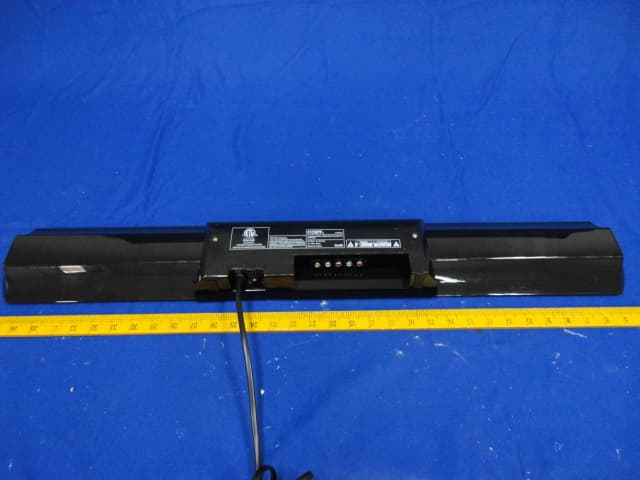
Click to zoom
Application Details
- Equipment Class
- DXX - Part 15 Low Power Communication Device Transmitter
- Date of Grant
- May 30, 2012
- Application Purpose
- Original Equipment
- Date of Application
- May 30, 2012
- Equipment Note
- 2.4G DIGITAL WIRELESS SOUNDBAR SYSTEM
- Frequency Range
- 2404.00000000 - 2479.00000000
- Country
- China
Documents & Files
Document Text
Text extracted from the exhibit documents filed with the FCC. Open a document above to read the original.
Users Manual
Read this manual carefully to get the best performance from 2.1 System 2.4GHz DIGITAL WIRELESS SOUNDBAR SYSTEM CSMP95 OWNER`S MANUAL WARNINGS AND PRECAUTIONS ! The lightning flash with arrowhead symbol, within an equilateral triangle, is intended to alert the user to the presence of uninsulated "dangerous voltage" within the product's enclosure that may be of sufficient magnitude to constitute a risk of electric shock to persons. This symbol is intended to alert the user to the presence of important operation and maintenance (servicing) instructions in the literature accompanying the appliance. 1 WARNING: To reduce the risk of fire or electric shock, do not expose this apparatus to rain or moisture. The apparatus shall not be exposed to dripping or splashing and that no objects filled with liquids, such as vases, shall be placed on apparatus. WARNING: To reduce the risk of electric shock, do not remove cover (or back). FCC STATEMENT FCC STATEMENT 1. This device complies with Part 15 of the FCC Rules. Operation is subject to the following two conditions: (1) This device may not cause harmful interference. (2) This device must accept any interference received, including interference that may cause undesired operation. 2. Changes or modifications not expressly approved by the party responsible for compliance could void the user's authority to operate the equipment. NOTE: This equipment has been tested and found to comply with the limits for a Class B digital device, pursuant to Part 15 of the FCC Rules. These limits are designed to provide reasonable protection against harmful interference in a residential installation. This equipment generates uses and can radiate radio frequency energy and, if not installed and used in accordance with the instructions, may cause harmful interference to radio communications. However, there is no guarantee that interference will not occur in a particular installation. If this equipment does cause harmful interference to radio or television reception, which can be determined by turning the equipment off and on, the user is encouraged to try to correct the interference by one or more of the following measures: Reorient or relocate the receiving antenna. Increase the separation between the equipment and receiver. Connect the equipment into an outlet on a circuit different from that to which the receiver is connected. Consult the dealer or an experienced radio/TV technician for help. 2 Caution: Please read carefully all the following important safeguards to en- sure safe operation. 1. Read these Instructions. 2. Keep these Instructions. 3. Heed all Warnings. 4. Follow all instructions. 5. Do not use this apparatus near water. 6. Clean only with a dry cloth. 7. Do not block any ventilation openings. Install in accordance with the manufacturer's instructions. 8. Do not install near any heat sources such as radiators, heat registers, stoves, or other apparatus (including amplifiers) that produce heat. 9. Do not defeat the safety purpose of the polarized or grounding - type plug. A polarized plug has two blades with one wider than the other. When the provided plug does not fit into your outlet, consult an electrician for replacement of the obsolete outlet. 10. Protect the power cord from being walked on or pinched particularly at plugs, convenience receptacles, and the point where they exit from the apparatus. 11. Only use attachments/accessories specified by the manufacturer. 12. Use only with a cart, stand, tripod, bracket, or table specified by the manufacturer, or sold with the apparatus. When a cart or rack is used,use caution when moving the cart/ apparatus, combination to avoid injury from tip-over. IMPORTANT SAFETY INSTRUCTIONS 3 4 IMPORTANT SAFETY INSTRUCTIONS 13. Unplug this apparatus during lightning storms or when unused for long periods of time. 14. Refer all servicing to qualified service personnel. Servicing is required when the apparatus has been damaged in any way, such as power-supply cord or plug is damaged, liquid has been spilled or objects have fallen into the apparatus, the apparatus has been exposed to rain or moisture, does not operate normally, or has been dropped. 15. WARNING: The mains plug (appliance coupler) is used as disconnect device, the disconnect device shall remain readily operable. 16. The battery (battery or batteries or battery pack) shall not be exposed to excessive heat such as sunshine, fire or the like. 17. No naked flame sources, such as lighted candles, should be placed on the apparatus. 18. Label marking is located at the bottom of the apparatus. 19. This equipment is a Class II or double insulated electrical appliance. It has been designed in such a way that it does not require a safety connection to electrical earth. Contents: - Remote Control x 1 - Sx 8 - Wall mounting brackets x 2 - Wx 2 - RCA to RCA x 1 - RCA to 3.5mm x 1 - Coaxial Cable x 1 - Ax 8 - User's Manual x 1 - Installation Guidex 1 crew all mounting screw ssembling bolt PARTS LIST FRONT PANEL - CONTROLS AND FUNCTIONS 5 5.: Power Standby STANDBYButton. 1. Remote Sensor. 6.INPUT:Input Selection Button. 2. STANDBY:Standby Input Indicator. 8.VOL+: Volume Upward Adjustment Button. 7.VOL-: Volume Downward Adjustment Button. 12 3 4 5678 3. TV:TV Input Indicator. 4. AUX/COAX:AUX and Coaxial Input Indicator. 40 Watt + 2 x 20 Watt AC 120V~60Hz 2.4GHz DIGITAL WIRELESS SYSTEM SOUNDBAR MADE IN CHINA CSMP95 FCC ID:xxxxxxx This device complies with Part 15 of the FCC Rules. Operation is subject to the following two conditions: (1) this device may not cause harmful interference, and (2)this device must accept any interference received, including interference that may cause undesired operation. XXXXXXX CONFORMS TO ANSI/UL STD.60065 CERTIFIED TO CAN/CSA STD.C22.2 No.60065 6 3.AUX Stereo Audio Input.Right 4.AUX Stereo Audio Input.Left REAR PANEL - CONTROLS AND FUNCTIONS 9 10 5.TV Stereo Audio Input.Right 6.TV Stereo Audio Input.Left 8 2 3 4 5 1 6 1.Power On/Off Switch.(Sou…
Text truncated - open the document above for the full version.
Cover Letter(s)
SCS-F18: Project and Product Certification Representative Authorization Letter Page 1 of 2 Rev 3.0 775 Montague Expressway Milpitas, CA 95035 Tel: 408-526-1188 Fax: 408-526-1088 Email: [email protected] Project and Product Certification Representative Authorization Letter Revision History Reason for Amendment (current / obsolete) From To Approved Date Initial Release (obsolete) 1.0 1.0 Nov-14-2006 Revised wording (obsolete) 1.0 2.0 Sept–25-2007 Updated company template (current) 2.0 3.0 Jan-31-2012 SCS-F18: Project and Product Certification Representative Authorization Letter Page 2 of 2 Rev 3.0 ZHONGSHAN HITREND TECHNOLOGY CO., LTD 2012/5/17 To: SIEMIC, INC. 775 Montague Expressway, Milpitas, CA 95035 USA Dear Sir/Madam, Re: Project and Product Certification Representative Authorization Letter We, __ ZHONGSHAN HITREND TECHNOLOGY CO., LTD _hereby authorize SIEMIC, INC. to act as a Certification Body for certifying for the following project(s): Product description: 2.4G DIGITAL WIRELESS SOUNDBAR SYSTEM model name:AIO-860 We affirm that between SIEMIC and _ ZHONGSHAN HITREND TECHNOLOGY CO., LTD _, any difference in understanding, including test plan, measurement methods, applicable standards and relevant procedures and processes have been resolved prior to commencement of testing activities. Sincerely, Client’s signature : Client’s name / title : ENGINEER MANAGER Contact information / address: NO 42 INDUSTRIAL CENTRAL ROAD, XIOALAN, ZHONGSHAN, GUANGDONG,CHINA
Cover Letter(s)
SCS-F19: Confidentiality Request Letter Page 1 of 2 Rev 3.0 775 Montague Expressway Milpitas, CA 95035 Tel: 408-526-1188 Fax: 408-526-1088 Email: [email protected] Confidentiality Request Letter Revision History Reason for Amendment (current / obsolete) From To Approved Date Initial Release (obsolete) 1.0 1.0 Nov-14-2006 Adding CFR 2.459 (obsolete) 1.0 2.0 August – 11 - 2008 Updated company template & Added text box (current) 2.0 3.0 Jan-31-2012 SCS-F19: Confidentiality Request Letter Page 2 of 2 Rev 3.0 ZHONGSHAN HITREND TECHNOLOGY CO., LTD 2012/5/17 To: Federal Communications Commission Authorization and Evaluation Division 7435 Oakland Mills Road Columbia, MD Subject: Permanent Confidentiality Request for FCC ID: NZGAIO-860 We hereby request confidential treatment of information accompanying this application as outlined below: Block Diagram Schematics Operational Description The above materials contain trade secrets and proprietary information not customarily released to the public. The public disclosure of these materials may be harmful to the applicant and provide unjustified benefits to its competitors. The applicant understands that pursuant to Section 0.457 & 0.459 of the Rules, disclosure of this application and all accompanying documentation will not be made before the date of the Grant for this application. Sincerely, Client’s signature : Client’s name / title : ENGINEER MANAGER Contact information / address: NO 42 INDUSTRIAL CENTRAL ROAD, XIOALAN, ZHONGSHAN, GUANGDONG,CHINA
External Photos
1. PHOTOGRAPH OF EUT Figure 1 General Appearance of the EUT Figure 2 General Appearance of the EUT
ID Label/Location Info
Lable Location
Internal Photos
Figure 1 General Appearance of the EUT Figure 2 Component Side of the PCB Figure 3 Component Side of the PCB Figure 4 Component Side of the PCB Figure 5 Component Side of the PCB Figure 6 Component Side of the PCB Antenna
Test Report
FCC ID: NZGAIO-860 EST Technology Co.,Ltd Report No. ESTE-R1205001 FCC PART 15C TEST REPORT FOR CERTIFICATION On Behalf of ZHONGSHAN HITREND TECHNOLOGY.,LTD 2.4G DIGITAL WIRELESS SOUNDBAR SYSTEM Model Number: AIO-860; Additional Mode: CSMP95 FCC ID: NZGAIO-860 Prepared for : ZHONGSHAN HITREND TECHNOLOGY.,LTD NO 42 INDUSTRIAL CENTRAL ROAD, XIOALAN, ZHONGSHAN, GUANGDONG, CHINA Prepared By : EST Technology Co., Ltd. Santun(guantai Road), Houjie Town, DongGuan City,GuangDong, China. Tel: 86-769-83081888-808 Report Number : ESTE-R1205001 Date of Test : May.5~May.12, 2012 Date of Report : May.15, 2012 FCC ID: NZGAIO-860 EST Technology Co.,Ltd Report No. ESTE-R1205001 TABLE OF CONTENTS Description Page 1. SUMMARY OF STANDARDS AND RESULTS.......................................................... 1-1 1.1. Description of Standards and Results .................................................................................. 1-1 2. GENERAL INFORMATION ......................................................................................... 2-1 2.1. Description of Device (EUT) ............................................................................................... 2-1 2.2. Tested Supporting System Details ....................................................................................... 2-2 2.3. EUT Configuration and operation conditions for test.......................................................... 2-3 3. POWER LINE CONDUCTED EMISSION TEST ....................................................... 3-1 3.1. Test Equipment .................................................................................................................... 3-1 3.2. Block Diagram of Test Setup ............................................................................................... 3-1 3.3. Power Line Conducted Emission Test Limits...................................................................... 3-1 3.4. Operating Condition of EUT................................................................................................ 3-2 3.5. Test Procedure...................................................................................................................... 3-2 3.6. Conducted Disturbance at Mains Terminals Test Results.................................................... 3-2 4. RADIATED EMISSION TEST ...................................................................................... 4-3 4.1. Test Equipment .................................................................................................................... 4-3 4.2. Block Diagram of Test Setup ............................................................................................... 4-3 4.3. Radiated Emission Limit Standard: FCC 15.209 and 15.249 .............................................. 4-4 4.4. Operating Condition of EUT................................................................................................ 4-5 4.5. Test Procedure...................................................................................................................... 4-5 4.6. Radiated Emission Test Results ........................................................................................... 4-5 5. 20 DB BANDWIDTH TEST ........................................................................................... 5-1 5.1. Test Equipment .................................................................................................................... 5-1 5.2. Limit..................................................................................................................................... 5-1 5.3. Test Results .......................................................................................................................... 5-1 6. BAND EDGE COMPLIANCE TEST ............................................................................ 6-1 6.1. Test Equipment .................................................................................................................... 6-1 6.2. Limit..................................................................................................................................... 6-1 6.3. Test Produce ......................................................................................................................... 6-1 6.4. Test Results .......................................................................................................................... 6-2 7. PHOTOGRAPH OF TEST ............................................................................................. 7-1 7.1. Photos of Conducted Emission Test (0.15-30MHz) ........................................................... 7-1 7.2. Photos of Radiated EmissionTest(30-1000MHz)..................................................7-2 8. PHOTOGRAPH OF EUT ............................................................................................... 8-1 FCC ID: NZGAIO-860 EST Technology Co.,Ltd Report No. ESTE-R1205001 TEST REPORT CERTIFICATION Applicant :ZHONGSHAN HITREND TECHNOLOGY.,LTD Manufacturer :ZHONGSHAN HITREND TECHNOLOGY.,LTD EUT Description :2.4G DIGITAL WIRELESS SOUNDBAR SYSTEM FCC ID : NZGAIO-860 (A) MODEL NO. : AIO-860 (B)Additional Model : CSMP95 The products are difference in model number and appearance only. (C) SERIAL NO. : N/A (D) Trade Name : COBY; CCyAudio (D) POWER SUPPLY : AC 120V/60Hz (E) TEST VOLTAGE : AC 120V/60Hz Tested for comply with: FCC Rules and Regulations Part 15 Subpart C: 2011 Test procedure used: ANSI C63.4:2003 The device described above is tested by EST Technology Co., Ltd. to confirm comply with all the FCC Part 15 Subpart C requirements. The test results are contained in this test report and EST Technology Co., Ltd. is assumed full responsibility for the accuracy and completeness of these tests. Also, this report shows that the Equipment under test (EUT) is to be technically compliant with the FCC requirements. Prepared by: Tested by: Approved by: Ada / Assistant Tony.T…
Text truncated - open the document above for the full version.
Test Setup Photos
1. PHOTOGRAPH OF TEST 1.1. Photos of Conducted Emission Test (0.15-30MHz) 1.2. Photos of Radiated Emission Test (30-1000MHz) (Above 1000MHz)
Contact Information
Applicant
MIAO FUNG(ENGINEER MANAGER)
Test Firm
EST Technology Co.,LtdIceman Hu
[email protected]86-769-83081888
Technical Specifications
| # | Rule Parts | Frequency Range | Power Output |
|---|---|---|---|
| 1 | 15C | 2.40 GHz - 2.48 GHz | - |
Other Applications from ZHONGSHAN HITREND TECHNOLOGY CO., LTD

NZGCY-528
Oct 15, 2014Bluetooth Speaker
Equipment Class
DSS - Part 15 Spread Spectrum Transmitter
NZGCY-902
Oct 15, 2014Bluetooth Speaker
Equipment Class
DSS - Part 15 Spread Spectrum Transmitter
NZGCY-901
Jun 02, 2014Bluetooth Speaker
Equipment Class
DSS - Part 15 Spread Spectrum Transmitter