NZSST-880RSURTU WIRELESS LOCAL LOOP
Smartrunk Systems Inc
Click to zoom
Application Details
- Equipment Class
- TNB - Licensed Non-Broadcast Station Transmitter
- Date of Grant
- Nov 22, 1998
- Application Purpose
- Original Equipment
- Date of Application
- Jun 25, 1998
- Equipment Note
- RTU WIRELESS LOCAL LOOP
- Frequency Range
- 806.00000000 - 824.00000000
- Company
- Smartrunk Systems Inc
- Country
- United States
Documents & Files
Document Text
Text extracted from the exhibit documents filed with the FCC. Open a document above to read the original.
Users Manual
INSTALLATION Mounting The ST-880 RSU should be mounted to an interior wall in a location that is close to an AC power outlet. In addition, in order to reduce RF signal losses, the RSU should be located such that the length of the feedline coax to the antenna is minimized. Power The ST-880 RSU is powered by a small step down AC to AC wall plug-in transformer specified for your local power. Connect the wall plug-in transformer supplied with the RSU to the power connector on the RSU. Telephone Set The ST-880 RSU uses a standard RJ-11 modular telephone jack. Connect your telephone equipment to this jack. The ST-880 RSU provides ringing voltage sufficient to ring up to four telephone devices. If telephone audio level adjustments are required, refer to Telephone Level Adjustments in the Service Alignment section, page 4-1. Antenna Several antenna options are available for the ST-880 RSU, depending on the distance from the SkyLink radio base station. If your installation uses the 3 dB glass mount antenna option, attach it to the SMA connector on the RSU so that the whip antenna is in a vertical position pointed up. If your installation uses a directional yagi antenna, mount the yagi antenna at a high location that is above any obstructions that might hinder the signal to the SkyLink base station. Point the yagi so that it is pointed directly at the base station (RS-HUB). Keep the antenna at least 1 meter away from personnel. When using heavier, low loss cable (LMR 400 or 600), use a LMR240 jumper cable to connect between the main feedline and the RSU. In order to minimize signal loss, keep the feedline as short as possible.
Cover Letter(s)
Federal Communications Commission 7435 Oakland Mills Road Columbia MD 21046 Subject :Application for Type Acceptance per 2.983 Reference:Applicant:SMARTRUNK SYSTEMS, INC. FCC ID No:NZSST-880RSU Model No:ST-880RSU To who it may concern : Enclosed please find the information as required under FCC Part 2 section 2.983. A. Applicant :SMARTRUNK SYSTEMS, INC. 23278 BERNHARDT ST. HAYWARD CA 94545-1621 Manufacturer:Same as Applicant B. Equipment :RTU WIRELESS LOCAL LOOP C. Equipment will be manufactured in quantity. D. (1) Type of Emission : F3E (2) Frequency Range : TX:806-825MHZ, RX:851-870MHZ (3) Design power : +28dBm - +30dBm (4) Maximum power rating as defined in Part 90:30dBm (5) Power amplifier:+6V, [email protected], Pre-amplifier:+6V, [email protected] (6) Please refer to Exhibit 8, Theory of Operation . Confidentiality is requested for this item. (7) Circuit Diagram : Exhibit 7. Confidentiality is requested for this item. (8) Instruction Books: Exhibit 6 (9) Enclosed. Please refer to Exhibit 6. (10)Please refer to Exhibit 8, Theory of operation. Confidentiality is requested for this item. (11) Please refer to Exhibit 8, Theory of operation. Confidentiality is requested for this item. (12) Not Applicable. EUT is using the analog modulation. E. Technical Data : Enclosed. F. FCC ID Label Drawing : Enclosed . G. EUT photo : Enclosed H.:N/A I: N/A J: N/A If you have any question, please contact the undersigned. Best Regards Mike C.I. Kuo / Vice President Compliance Consulting Services
Cover Letter(s)
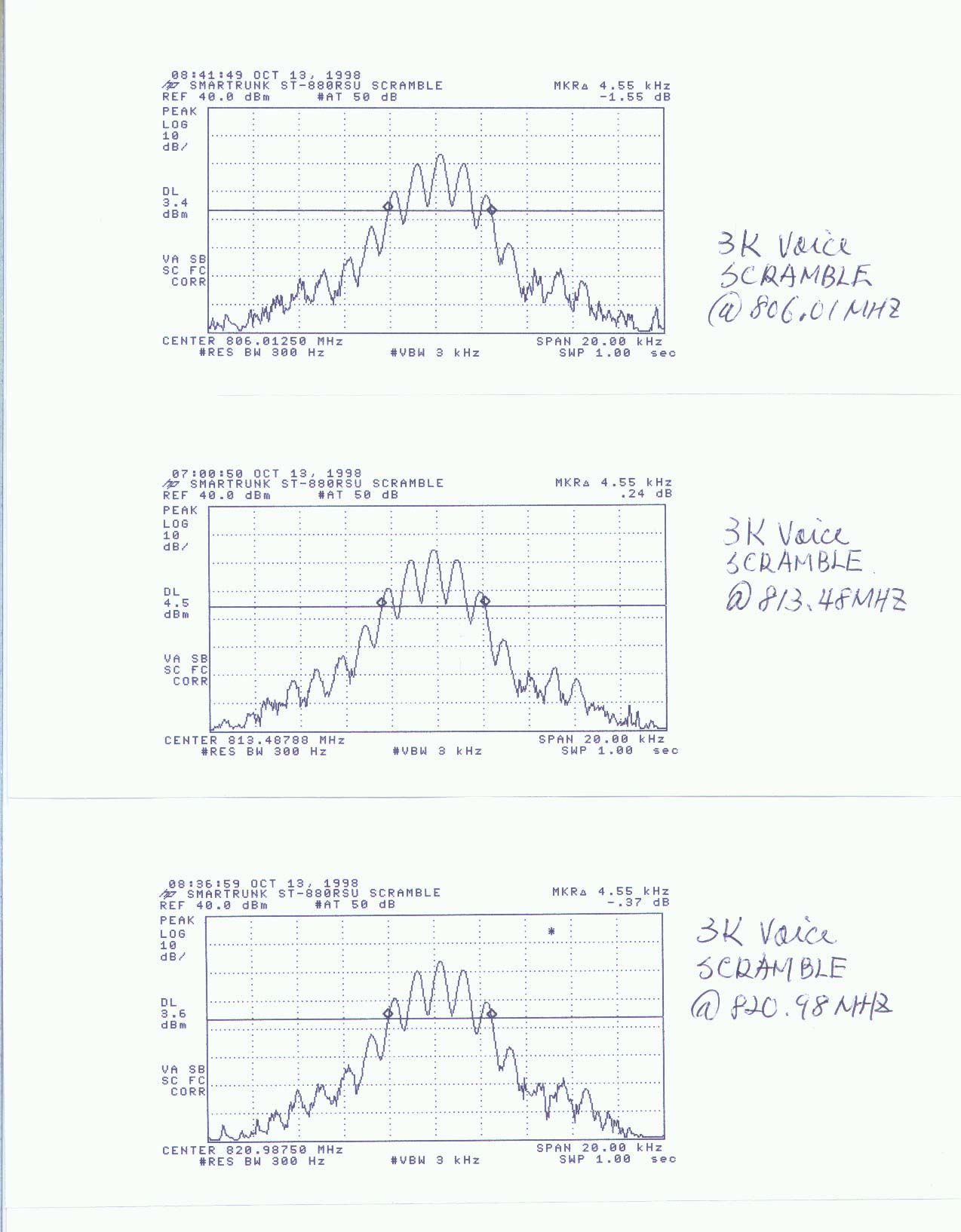
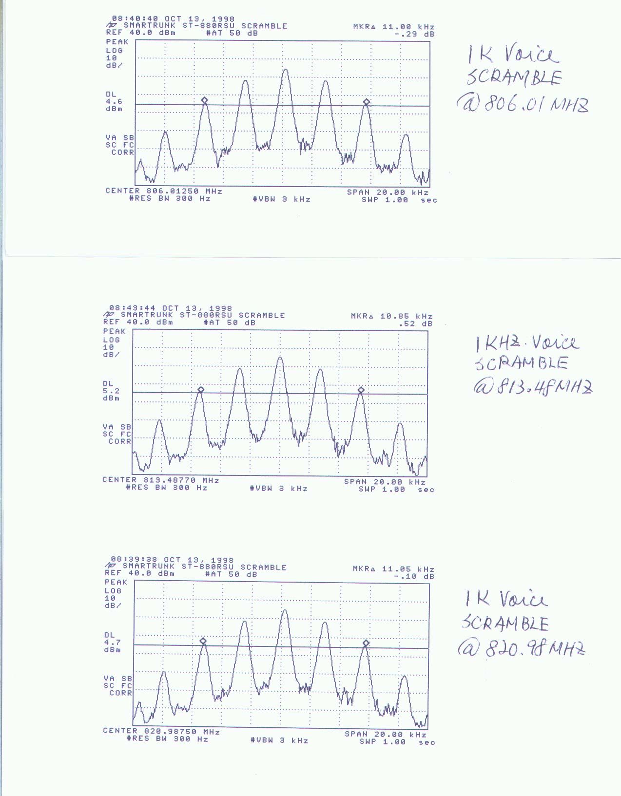
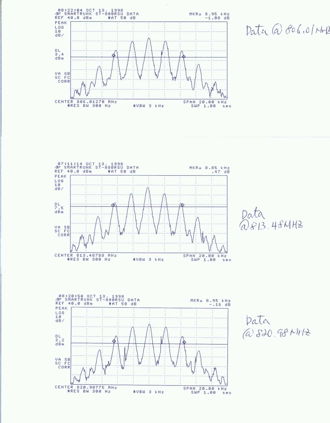
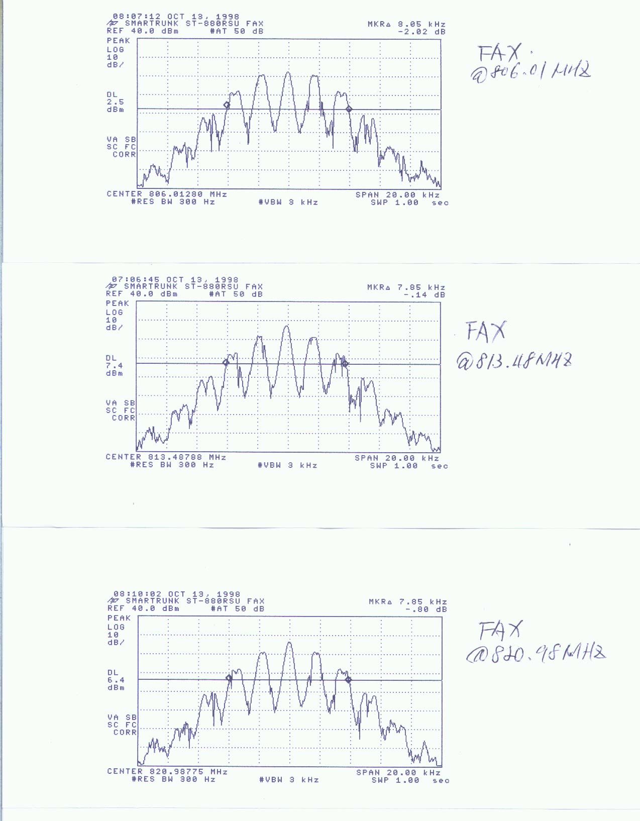
Response to questions about Smartrunk submittal FCC ID# NZSST- 880RSU, (Correspondence ID: 3297), 731 Confirmation Number: EA89955. 1. We are submitting occupied bandwidth plots for scrambled voice, FAX and data via FCC Web Site. 2. Necessary bandwidth calculations 2M+2DK: Voice and scrambled voice: M=3kHzD=5kHzK=1 2M+2DK=16kHz Data and FAX: M=2kHzD=5kHzK=1.1 2M+2DK=15.4kHz 3. Yes submittal for FCC part 90. 4.Masks G and H are applicable to transmitters without audio low pass filter. All types of emissions from this unit pass through the audio low filter. As indicated in Smartrunk document no:502-4908, page 2 of 3 " 7. TX Audio path : Higher Audio Frequency Attenuating: The low pass amplifier (U12A) attenuates the higher audio frequency that cut of the TX audio frequency above 3000MHz." Also please refer block diagram " Summing Amp (U12/R42). 5. We are providing the test procedure used to determine modulation limiting data previously provided for FCC sect. 2.987(b): EUT’s input was connected to audio generator, output was connected to test receiver. EUT was adjusted according to tune up procedure. A 1000Hz tone was applied from audio generator, the level of the tone was adjusted to give 60% of full rated system deviation. The level was increased by 20dB in less than 0.1 seconds. Instantaneous and steady state deviation was measured at and after increase in audio level. Keeping same level the audio frequency was slowly swept from 300Hz 3000Hz and maximum deviation was measured. This procedure was done for positive and negative deviation. 6. Chart below showing frequencies at temperatures and voltages: FREQUENCY STABILITY TEMPFREQFREQFREQ DEG CMHZMHZMHZ -30806.01080815.51080824.98580 -20806.01080815.51085824.98585 -10806.01115815.51105824.98610 0806.01120815.51110824.98620 10806.01135815.51120824.98630 20806.01130815.51130824.98630 30806.01130815.51120824.98630 40806.01125815.51125824.98625 50806.01135815.51130824.98640 TOTAL DRIFT 550HZ500HZ600HZ VOLTAGE 93.5 TO806.01133815.51160824.98644 138VAC806.01179815.51165824.98700 TOTAL DRIFT 490HZ50HZ560HZ 7. Instructions are changed for antenna installation in Guide to Installation and Operation (Exhibit 6 page 1-2). Revised page is submitted via FCC Web Site. Calculations for permissible distance are given below: Limit from FCC sect. 1.1310: 812MHz/1500 =0.54 mW/cm 2 Convert to E field:E= √0.54 mW/cm 2 x 3770 E=45v/m Distance calculation:D= √30 x P x G D= √30 x 1x 6 45 45 D= .298meters
Test Report
FCC CFR47 PART 90 TYPE ACCEPTANCE TEST REPORT FOR RTU WIRELESS LOCAL LOOP MODEL:ST-880RSU FCC ID: NZSST-880RSU REPORT NUMBER: 98E7323 ISSUE DATE:JUNE23,1998 Prepared for SMARTRUNK SYSTEMS 23278 BERNHARDT ST HAYWARD CA, 94545 USA Prepared by COMPLIANCE ENGINEERING SERVICES, INC. 1366 BORDEAUX DRIVE SUNNYVALE, CA 94089, USA TEL: (408) 752-8166 FAX: (408) 752-8168 0 COMPLIANCE CONSULTING SERVICESDOCUMENT NO:CCSUP4031A 1366 BORDEAUX DRIVE SUNNYVALE, CA 94089 USA TEL:(408) 752-8166 FAX:(408) 752-8168 This report shall not be reproduced except in full, without the written approval of CCS. TABLE OF CONTENTS PAGE 1.VERIFICATION OF COMPLIANCE............................................................................................................1 2.PRODUCT DESCRIPTION............................................................................................................................2 3.TEST FACILITY..............................................................................................................................................2 4.ACCREDITATION AND LISTING...............................................................................................................2 5.MEASUREMENT INSTRUMENTATION....................................................................................................2 6.MEASURING INSTRUMENT CALIBRATION...........................................................................................3 7.UNITS OF MEASUREMENT.........................................................................................................................3 8.CLASSIFICATION OF DIGITAL DEVICE.................................................................................................3 9.RADIATED EMISSION LIMITS...................................................................................................................4 10. RADIATED EMISSION TEST PROCEDURE..............................................................................................4 11.AMBIENT CONDITIONS...............................................................................................................................5 12.TEST EQUIPMENT LIST...............................................................................................................................5 13.EUT SETUP PHOTOS.....................................................................................................................................6 14.TEST RESULT SUMMARY...........................................................................................................................9 FCC PART 2 TYPE ACCEPTANCE TEST REQUIREMENT:.....................................................................11 SECTION 2.985 RF POWER OUTPUT..............................................................................................................11 SECTION 2.987 MODULATION CHARACTERISTICS....................................................................................11 SECTION 2.989 OCCUPIED BANDWIDTH......................................................................................................11 SECTION 2.991 SPURIOUS EMISSION AT ANTENNA TERMINALS...........................................................12 SECTION 2.995 FREQUENCT STABILITY.......................................................................................................12 SECTION 2.993 FIELD STRENGTH OF SPURIOUS RADIATION.................................................................13 15.EXTERNAL I/O CABLE CONSTRUCTION DESCRIPTION.................................................................13 16. CONFIGURATION BLOCK DIAGRAM........................................................................................................14 EXHIBITS 1.FCC 731 FORM 2.APPLICATION LETTER FROM CCS 3.AUTHORIZATION LETTER 4.PROPOSED FCC ID LABEL FORMAT 5.REQUEST FOR CONFIDENTIALITY LETTER 6.USER MANUAL 7.SCHEMATIC/PARTS LISTS, DOCUMENT#502-4911, 502-5027 8.THEORY OF OPERATION , DOCUMENT#502-4908 9.COMPONENT LOCATOR, DOCUMENT#502-4912 10.PRODUCT SPECIFICATION, DOCUMENT#502-4907 11.BLOCK DIAGRAM REPORT NO:98E7323FCC ID:NZSST-880RSUDATE:06/23/1998 EUT:SMARTRUNK SKYLINK ST-880RSU 1 COMPLIANCE CONSULTING SERVICESDOCUMENT NO:CCSUP4031A 1366 BORDEAUX DRIVE SUNNYVALE, CA 94089 USA TEL:(408) 752-8166 FAX:(408) 752-8168 This report shall not be reproduced except in full, without the written approval of CCS. 1.VERIFICATION OF COMPLIANCE COMPANY NAME:SMARTRUNK SYSTEMS 23278 BERNHARDT ST HAYWARD CA, 94545 CONTACT PERSON: GEORGE Z H ZHANG / PROJECT ENGINEER TELEPHONE NO:510-887-1950 MODEL NO/NAME:ST-880RSU SERIAL NO:N/A DATE TESTED:MAY 4, 1998 TYPE OF EQUIPMENT:SKYLINK RTU LOCAL LOOP MEASUREMENT DISTANCE:3 METER TECHNICAL LIMIT:FCC 90.210 FCC RULES:PART 15, PART 90 EQUIPMENT AUTHORIZATION PROCEDURE TYPE ACCEPTANCE The above equipment was tested by Compliance Consulting Services for compliance with the requirements set forth in the FCC CFR 47, PART 15 AND 90. The results of testing in this report apply to the product/system which was tested only. Other similar equipment will not necessarily produce the same results due to production tolerance and measurement uncertainties. Approved By Compliance Consulting Services, Inc. Mike C. I. Kuo / Vice President REPORT NO:98E7323FCC ID:NZSST-880RSUDATE:06/23/1998 EUT:SMARTRUNK SKYLINK ST-880RSU 2 COMPLIANCE CONSULTING SERVICESDOCUMENT NO:CCSUP4031A 1366 BORDEAUX DRIVE SUNNYVALE, CA 94089 USA TEL:(408) 752-8166 FAX:(408) 752-8168 This report shall not be reproduced except in full, without the written approval of CCS. 2. PRODUCT DESCRIPTION ST-880RSU SkyLink Remote Subscriber Unit (RSU) is designed to operate in the SkyLink Wireless Local Loop System. The RSU is working in the 800MHz frequency band. The RSU contains two PCBs. One is a full duplex UHF transceiver unit. Another is a logic control unit with the telephone interface. For detailed description of the unit, please refer to Exhibit 8 – Theory of Operation. 3.TEST FAC…
Text truncated - open the document above for the full version.
Test Report
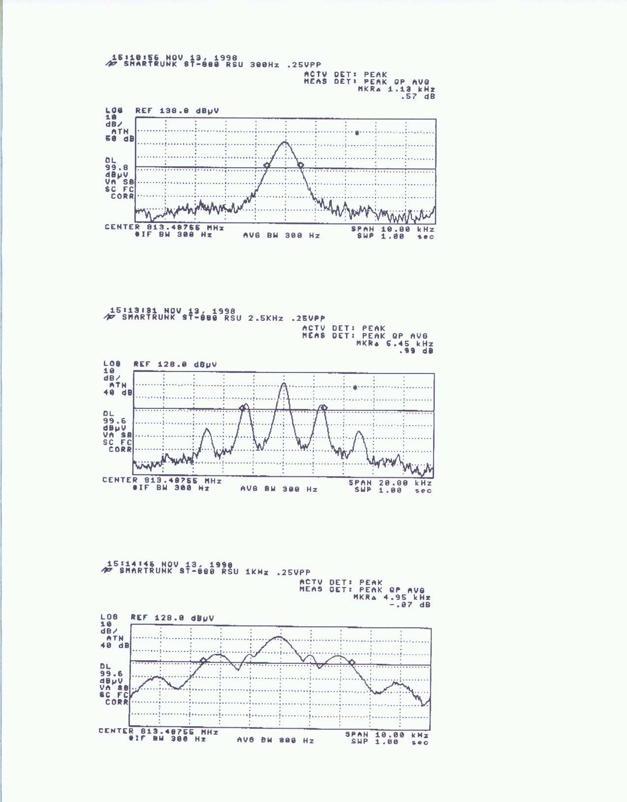
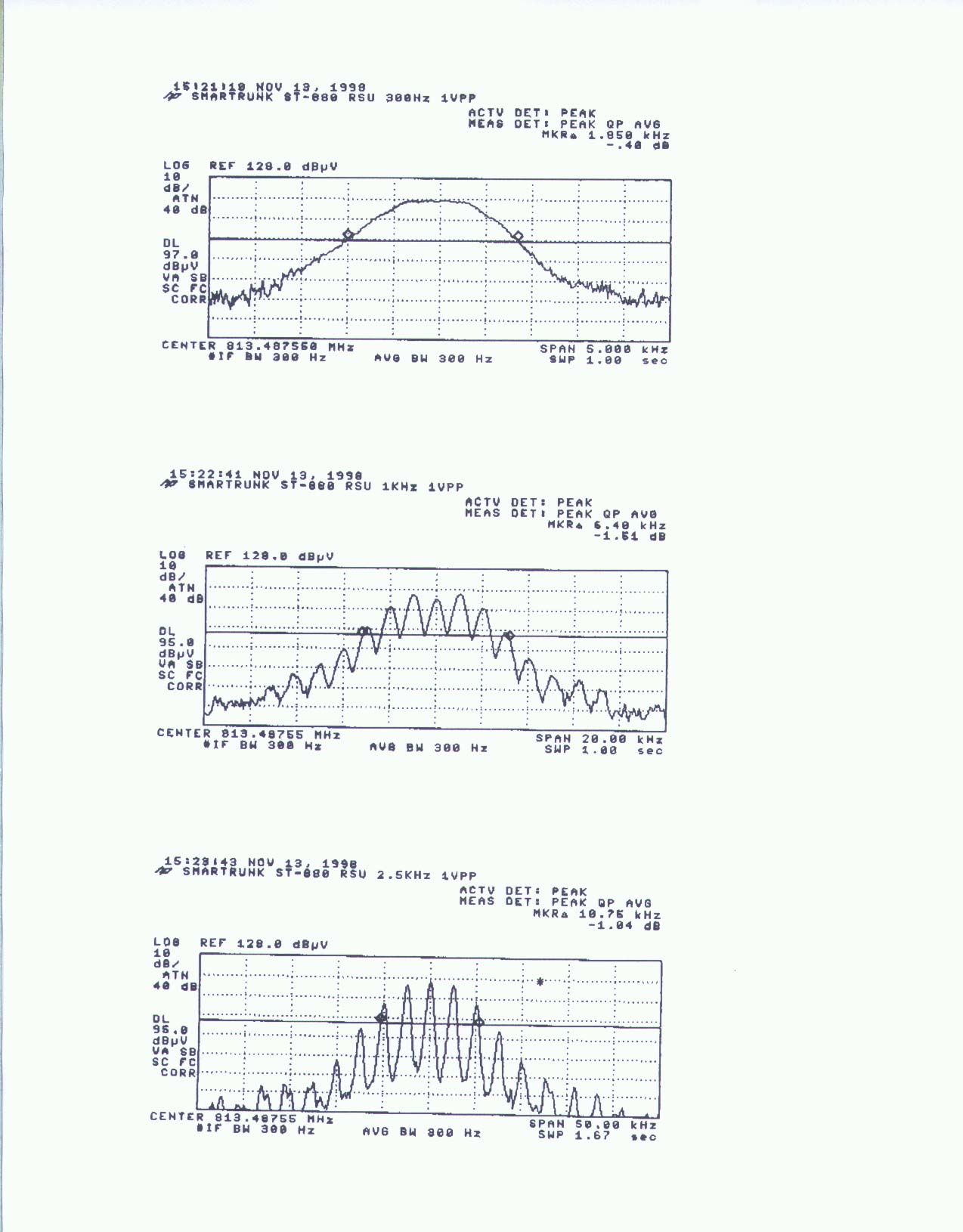
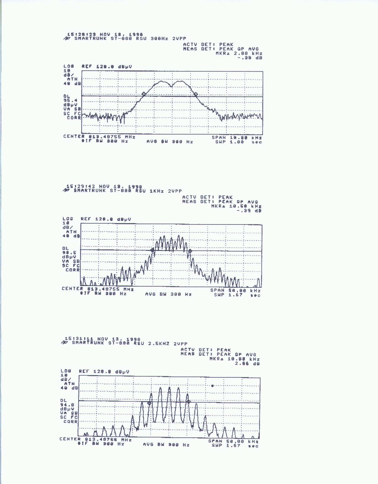
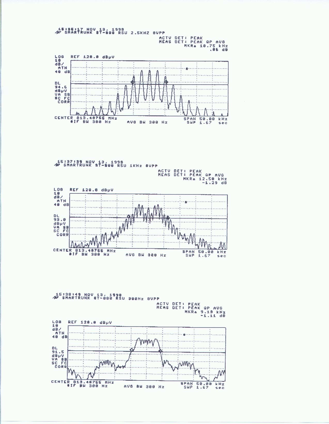
SMARTRUNK ST-880 RSU MODULATION LIMITING DATA11/13/98 VOLTSAUDIO FREQUENCY :5KHz IS MAX RATED DEVIATION PP:300Hz1KHz2.5KHz 0.25VPP.02KHz0.52KHz0.89KHz 0.5VPP0.31KHz0.96KHz1.69KHz 1VPP0.52KHz1.85KHz3.3KHz 2VPP0.93KHz3.51KHz3.662KHz 4VPP1.8KHz4.53KHz3.62KHz 8VPP3.85KHz4.51KHz3.61KHz VOLTAGE WAS VARIED FOR 3 AUDIO FREQUENCIES. DEVIATION WAS MEASURE WITH RF COMM SET AND LISTED IN ABOVE CHART. PLOTS WERE MADE WITH SPECTRUM ANALYZER. 2VPP IS CONSIDERED MAXIMUM FOR PHONE LINE. EQUIPMENT USED FOR TEST: RF COMM SET: HP 8920A CAL DUE 8/8/00 TONE GENERATOR: AUTOMATED INDUSTRIAL ELECTRONICS 2TSG-1 CAL DUE 4/22/99 SCOPE: PHILIPS PM3335 CAL DUE 4/22/99 SPECTRUM ANALYZER: HP 8593EM CAL DUE 5/22/99 AUDIO GENERATOR PHONE JACK ADAPTER OSCILLOSCOPE EUT RF COMM SET SPECTRUIM ANALYZER
Contact Information
Applicant
George Z. Zhang(Project Engineer)
510-887-1950Fax: 510-887-4011
Technical Contact
COMPLIANCE ENGINEERING SERVICESMIKE KUO
[email protected]4087528166
1366 BORDEAUX DRIVE · SUNNYVALE, California · United States
Non-Technical Contact
COMPLIANCE ENGINEERING SERVICESMIKE KUO
[email protected]4087528166
Test Firm
Compliance Certification Services IncSteve Cheng
Technical Specifications
| # | Rule Parts | Frequency Range | Power Output | Emission | Tolerance |
|---|---|---|---|---|---|
| 3 | 9 | 806 MHz - 824 MHz | 656.00 mW | 16K0F3E | 600 Hz |