O23AR726315 MHZ TRANSMITTER
ULTIMATE AIR FRESHENER, INC.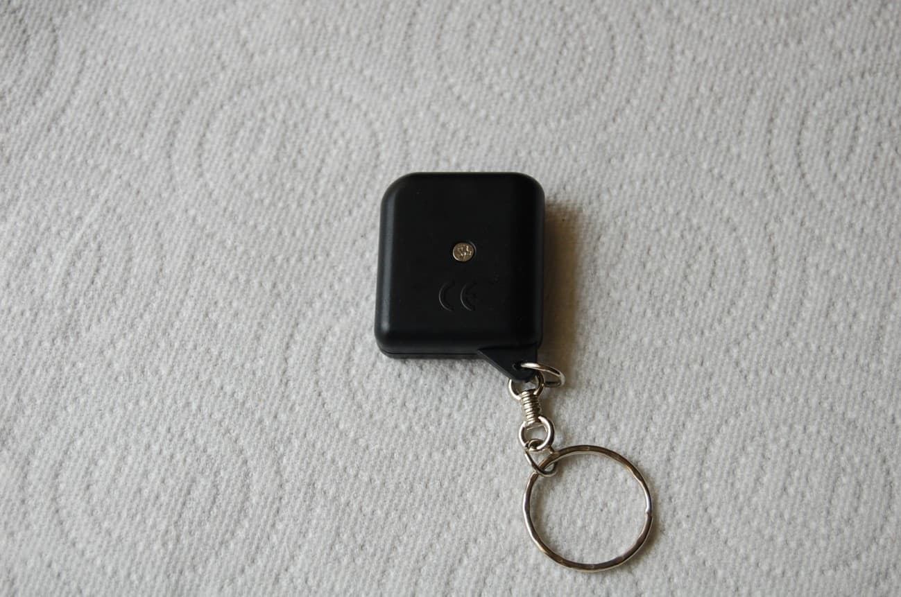
Click to zoom
Application Details
- Equipment Class
- DSC - Part 15 Security/Remote Control Transmitter
- Date of Grant
- Jul 11, 2012
- Application Purpose
- Original Equipment
- Date of Application
- Jul 11, 2012
- Equipment Note
- 315 MHZ TRANSMITTER
- Frequency Range
- 315.00000000 - 315.00000000
- Company
- ULTIMATE AIR FRESHENER, INC.
- Country
- United States
Documents & Files
Document Text
Text extracted from the exhibit documents filed with the FCC. Open a document above to read the original.
Users Manual
FCC Regulations: FCC Regulations: This device complies with Part 15 of FCC rules. Operation is subject to the following two conditions: (1) This device may not cause harmful interference, and (2) This device must accept any interference received, including interference that may cause undesirable operation. This equipment has been tested and found to comply with the limits for a class B digital device, pursuant to Part 15 of the FCC Rules. These limits are designed to provide reasonable protection against harmful interference in a residential installation. This equipment generates and can radiate radio frequency energy and, if not installed and used in accordance with the instruction manual, may cause harmful interference to radio communications. However, there is no guarantee that interference will not occur in a particular installation. If this equipment does cause harmful interference to radio or television, which can be determined by turning the equipment OFF and ON, the user is encouraged to try to correct the interference by one or more of the following measures: •Reorient or relocate the receiving antenna. •Increase the separation between the equipment and receiver. •Connect the equipment into an outlet on a circuit different from that to which the receiver is connected. •Consult the dealer or an experienced radio / TV technician for help. Warning: Warning: Changes or modifications not expressly approved by the party responsible for compliance could void the user’s authority to operate this equipment. Warranty: Warranty: If, within one year from date of purchase, this product should become defective (except battery), due to faulty workmanship or materials, it will be repaired or replaced, without charge. Proof of purchase and a Return Authorization are required. Call toll free: 877-579-0469 for more information about our products and services. An installation video is available online here: www.ultimateairfreshener.com/installation.html 2193 Kirkwood Avenue Naples, FL 34112 www.ultimateairfreshener.com User's Manual User's Manual Ultimate Air Freshener System Ultimate Air Freshener System Model: 2011711GTR Model: 2011711GTR © 2012 Ultimate Air Freshener Inc. © 2012 Ultimate Air Freshener Inc. © 2012 Ultimate Air Freshener Inc. © 2012 Ultimate Air Freshener Inc. INSTALLATION INSTRUCTIONS INSTALLATION INSTRUCTIONS RESERVOIR: RESERVOIR: Fix fluid container in vertical position to an appropriate space either in engine room, driver’s cabin, trunk, or cargo area, any place where convenient for supplying air freshener fluid. Using metal mounting bracket, mark location and drill two 5/32” (4mm) diameter holes (It is recommended to use a smaller drill first and then enlarge them to size. Fasten with two sheet metal screws and secure tightly. (Note: if you are using fine thread screws with nuts then enlarge both holes to 1/4” (7mm)). Place fluid container on metal bracket. NOZZLE: NOZZLE: Your air handler unit box will always be located on the passenger side underneath the dash. Select an appropriate location for the nozzle between the blower motor and the evaporator (Hint: the blower motor is always on the right side of the air handler box). In some cases your vehicle might have a cabin filter, if this is your case then you want to place the nozzle in between the cabin filter and the evaporator. When you have found a location mark and drill a hole size 11/32 (8.5mm) (in some cases due to the type of construction you might need to enlarge the hole to 23/64” (9mm) at an angle pointing to the evaporator). CAUTION RUN DRILL SLOWLY AS IT WILL TRY TO PULL ONCE IT BRAKES THRU THE PLASTIC! Run the clear tubing through an appropriate location hidden and plug into the nozzle. (Note: Make sure hose is not bent or pinched.) RECEIVER BOX: RECEIVER BOX: Place receiver in a desired location. (Preferably close to the reservoir container) Using the plastic crimp caps, connect the blue wire from the receiver to the red wire provided with the unit and crimp cap tightly. Cut red wire lead to a length that will reach the pump attached to the reservoir container. Connect the end to the red wire on the pig tail provided and crimp cap tightly. Connect the two red wires on the receiver to the red wire provided and cut to length reaching the battery of the vehicle and crimp cap tightly. The end of the red lead connect it to the fuse holder and crimp cap tightly. Connect the fuse wire to the ring terminal and fasten to the positive battery terminal. Connect the black wire on the receiver to the black wire provided and cut to length reaching the negative on the battery. Connect the black wire on the pig tail from the pump to the black wire provided and cut to length reaching back to the battery. Connect the black wire from the pump and the black wire from the receiver to the ring terminal and fasten to the negative of the battery. (Make sure your wires are away from any sharp edges and keep away from direct contact with engine) (Note: Connect the pigtail to the pump on the reservoir container) FLUID AROMA: FLUID AROMA: Remove the white cap from the reservoir container and fill with Ultimate Air Freshener scented aromas. (Note: Make sure that you use only Ultimate Air Freshener’s products in this unit, as other products could cause harm to the unit and is not recommended due to certain chemicals. AIR FRESHENER OPERATION AIR FRESHENER OPERATION While car's vent is on, briefly press green button on air freshener's remote to dispense fluid when fragrance is desired. Do not press green button on remote more then 4 seconds as the scent could become too strong, and fluid would be wasted. Our aromas are very efficient and will extend your refill duration. © 2012 Ultimate Air Freshener Inc. © 2012 Ultimate Air Freshener Inc. © 2012 Ultimate Air Freshener Inc. © 2012 Ultimate Air Freshener Inc.
Block Diagram
Block Diagram
External Photos
APPLICANT: ULTIMATE AIR FRESHNER INC. FCC ID: O23AR726 EXTERNAL PHOTOS
Internal Photos
APPLICANT: ULTIMATE AIR FRESHNER INC. FCC ID: O23AR726 INTERNAL PHOTOS
Operational Description
Operation Description This wireless transmitter and receiver work as a momentary trigger activating the pump motor of the Ultimate Air Freshener unit. When the button on the remote is pushed, it trips a relay on the receiver which closes the loop, completes the circuit, and allows current to the pump motor. When the pump motor activates, fragrance fluid, from the Ultimate Air Freshener's fluid reservoir, is squirted into the vehicle's air handler unit box. When the button on the remote is released, the relay on the receiver releases the loop, breaking the circuit, and interrupting current to the pump motor. When the pump motor stops, the fragrance fluid is no longer squirted into the air handler unit box. This cycle is repeated as often as the operator desires renewed fragrance in the vehicle. Remote control Block Diagram Product Specification: •Antenna: 24CM Bronze Antenna •Frequency: 315 MHz •Data transmission rate/Modulation type: 5kbps/ASK •Acceptance sensitivity (25 ): 90 dBm°C Current drain: •Depth sleep mode: 7mA •Acceptance mode: 40 mA •Sending mode: 40 mA
Test Report
FCC PART 15.231 TEST REPORT LOW POWER UNLICENSED TRANSMITTER Applicant ULTIMATE AIR FRESHENER, INC. Address 2193 KIRKWOOD AVENUE NAPLES, FL 34112 FCC ID 023AR726 Product Description 315 MHZ TRANSMITTER Date Sample Received 8/31/2011 Date Tested 9/6/2011 Tested By JOE SCOGLIO Approved By MARIO R. DE ARANZETA Timco Report No. 1921ZT11TestReport.doc Test Results Pass Fail THE ATTACHED REPORT SHALL NOT BE REPRODUCED EXCEPT IN FULL WITHOUT THE WRITTEN APPROVAL OF TIMCO ENGINEERING, INC. 849 NW STATE ROAD 45 NEWBERRY, FL 32669 USA PH: 888.472.2424 OR 352.472.5500 FAX: 352.472.2030 EMAIL: [email protected] HTTP: //WWW.TIMCOENGR.COM Certificate # 0955-01 APPLICANT: ULTIMATE AIR FRESHENER, INC. FCC ID: 023AR726 REPORT: U\ULTIMATE AIR\1921ZT11\1921ZT11TestReport.doc Page 2 of 16 mdea 09.20.2007 TABLE OF CONTENTS GENERAL REMARKS .................................................................................................... 3 REPORT SUMMARY ...................................................................................................... 4 TEST ENVIRONMENT .................................................................................................... 4 TEST SETUP ................................................................................................................. 4 DUT SPECIFICATION .................................................................................................... 5 MANUFACTURE DECLARATION OF COMPLIANCE WITH PART 15.231(A) ...................... 6 TEST EQUIPMENT LIST ................................................................................................ 7 TEST PROCEDURES ..................................................................................................... 8 RADIATION INTERFERENCE ......................................................................................... 9 CALCULATION OF DUTY CYCLE ................................................................................. 11 OCCUPIED BANDWIDTH ............................................................................................. 15 POWER LINE CONDUCTED INTERFERENCE .............................................................. 16 APPLICANT: ULTIMATE AIR FRESHENER, INC. FCC ID: 023AR726 REPORT: U\ULTIMATE AIR\1921ZT11\1921ZT11TestReport.doc Page 3 of 16 mdea 09.20.2007 GENERAL REMARKS The attached report shall not be reproduced except in full without the written permission of Timco Engineering Inc. Summary The device under test does: fulfill the general approval requirements as identified in this test report not fulfill the general approval requirements as identified in this test report Attestations This equipment has been tested in accordance with the standards identified in this test report. To the best of my knowledge and belief, these tests were performed using the measurement procedures described in this report. All instrumentation and accessories used to test products for compliance to the indicated standards are calibrated regularly in accordance with ISO 17025 requirements. Certificate # 0955-01 I attest that the necessary measurements were made, under my supervision, at: Timco Engineering Inc. 849 NW State Road 45 Newberry, Fl 32669 Authorized Signatory Name: Mario de Aranzeta C.E.T. Compliance Engineer/ Lab. Supervisor Date: October/12/11 APPLICANT: ULTIMATE AIR FRESHENER, INC. FCC ID: 023AR726 REPORT: U\ULTIMATE AIR\1921ZT11\1921ZT11TestReport.doc Page 4 of 16 mdea 09.20.2007 REPORT SUMMARY Disclaimer The test results only relate to the item tested. Applicable Rule(s) FCC Pt 15.231, Pt 15.209, Pt 15.207, ANSI C63.4: 2003 Receiver The receiver portion of this system has been tested and meets all of the FCC requirements per FCC rules Part 15.109. A report was issued and a copy of this report is available upon request. TEST ENVIRONMENT Test Facility The test sites are located at 849 NW State Road 45 Newberry, FL 32669 USA. Test Condition: Temperature: 26ºC Relative humidity: 50% TEST SETUP Test Exercise (e.g software description, test signal, etc.): The DUT was placed in continuous transmit mode of operation. Deviation from the standard(s) No deviation from the standard(s) Modification to the DUT: No modification was made to the DUT. Supporting Peripheral Equipment Not applicable. The device is a stand-alone remote control radio. APPLICANT: ULTIMATE AIR FRESHENER, INC. FCC ID: 023AR726 REPORT: U\ULTIMATE AIR\1921ZT11\1921ZT11TestReport.doc Page 5 of 16 mdea 09.20.2007 DUT SPECIFICATION Applicant ULTIMATE AIR FRESHENER, INC. Description 315 MHZ TRANSMITTER FCC ID ZXKDG711 Frequency Range 315 MHz DUT Power Source 110–120Vac/50– 60Hz DC Power Battery Operated Exclusively Test Item Prototype Pre-Production Production Type of Equipment Fixed Mobile Portable APPLICANT: ULTIMATE AIR FRESHENER, INC. FCC ID: 023AR726 REPORT: U\ULTIMATE AIR\1921ZT11\1921ZT11TestReport.doc Page 6 of 16 mdea 09.20.2007 MANUFACTURE DECLARATION OF COMPLIANCE WITH PART 15.231(A) Item Description Yes No 1 Does this device transmit a signal that is only used to control another device? X 2 Does this device send data with this control signal? X 3 Does this device send data? Data is, things like: temperature, wind direction, fluid amount, rate of flow, etc. X 4 Does this device transmit continuously or automatically? X 5 If manually operated does this device stop transmitting within 5 seconds of releasing the button? X 6 If automatically operated does it deactivate 5 seconds after activation? 7 Does it transmit at regular predetermined intervals? X 8 Does it poll or send supervisory information? X If yes does it do a system integrity check? How often? 9 Is this a fire, security or safety of life device? X If YES does the device stop transmitting after the alarm condition is satisfied? 10 Duty cycle: Maximum on-time? Y If YES, on-time in 100 ms? If Other, please specify here 16.6 On time in -10.6 dB 4.9 11 Modulation technique: Please specify the modulation of the test sample, FM, or AFSK, or FSK, or…
Text truncated - open the document above for the full version.
Contact Information
Applicant
ARIEL RANCEL(OWNER AND PRESIDENT)
Test Firm
Timco Engineering, Inc.Bruno Clavier
Technical Specifications
| # | Rule Parts | Frequency Range | Power Output |
|---|---|---|---|
| 1 | 15.231 | 315 MHz - 315 MHz | - |