O2CPROTX-1Remote Birdlauncher Transmitter
FieldPro, LLC
Click to zoom
Application Details
- Equipment Class
- DSC - Part 15 Security/Remote Control Transmitter
- Date of Grant
- Jul 13, 2000
- Application Purpose
- Original Equipment
- Date of Application
- Jul 06, 2000
- Equipment Note
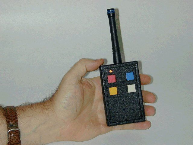
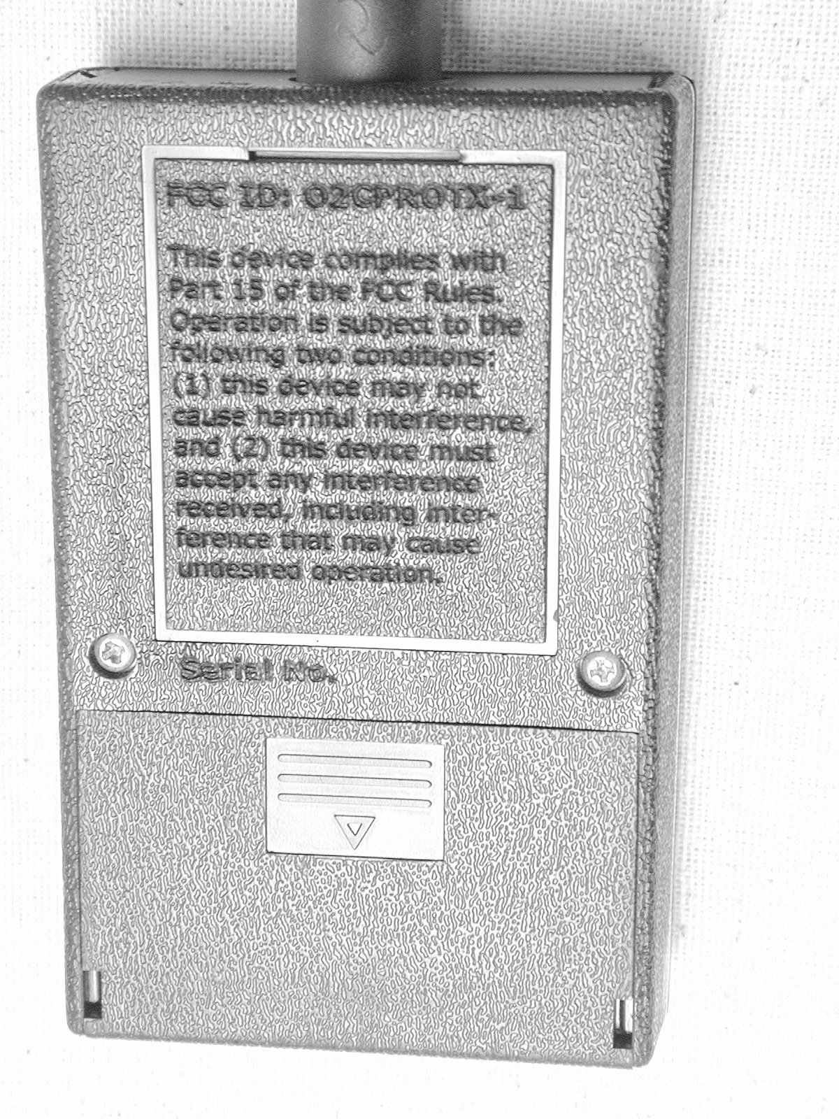
- Remote Birdlauncher Transmitter
- Frequency Range
- 414.00000000 - 418.00000000
- Company
- FieldPro, LLC
- Country
- United States
Documents & Files
Document Text
Text extracted from the exhibit documents filed with the FCC. Open a document above to read the original.
Users Manual
Thank you for p urch asing FieldPro equipm ent ! Your new equipm ent uses state of the art electronics so that we can offer you a quality product at an affordable price. TABLE OF CONTENTS TRANSMITTER ( ProTX) Getting started............................. 1 Controls...................................... 1 RECEIVER ( ProRX) Getting started............................. 2 Setting the ProRX color code switch.. 3 Mounting to the E-Z bird launcher... 4 Adjusting the launcher................... 5 Ready to go................................. 5 STORAGE AND RATINGS............... 6 WARRANTY AND SERVICE............. 7 FieldPro, ProTX, and ProRX are Trademarks of FieldPro, LLC First Printing April 1999 GETTING STARTED WITH TH E ProTX 1. Replacing the battery (in clu d e d ): The ProTX is designed to operate from one 9-volt alkaline battery . Open the battery com p artm ent on th e back of th e ProTX by sliding th e door any from th e ProTX antenna. In sta ll th e battery and re-install the b attery door. CONTROLS 1. Testing the co n tro l buttons: The ProTX was designed to operate up to fou r ProRX’s. Each button on th e top of th e ProTX will operate one ProRX. Press each button and make su re th e red LED tu rn s on when you press each button and turns off when you release the button . 2. O peration: The unit will operate up to 100 yard s consistently. It will operate th e best under line of sight conditions. The unit will not operate over hills but dow n in a valley is fine. Pressing th e b u tton fo r under one second will operate the ProRX if th e above conditions are follow ed. The unit is not waterproof but it is w ater resistant. Humidity and dam pness will not affect th e unit adversely 3. Color coding: All th e ProTX buttons are color coded to match th e ProRX so that you can tell which button on th e ProTX will operate which ProRX. Refer to the section titled “Setting the ProRX color code sw itch” to learn more about that subject. Note: Hold the ProTX aw ay from your body for optimal ran ge. Page 1 GETTING STARTED WITH TH E ProRX-1 1. Replacing the batteries (included): The ProRX is designed to operate from four AA alkaline b atteries. M ake su re th e pow er sw itch on the right side of the unit is set to OFF. Open th e battery com p a rtm en t on th e front of th e ProRX by sliding th e door to the right. In sta ll th e b atteries and re-install the b attery door. Turn the unit ON to position th e arm of the ProRX correctly th en turn th e unit back OFF. Page 2 SETTIN G TH E ProRX COLOR CODE SW ITC H 1. Opening the u n it: Lay th e unit on a flat su rface with th e battery door facing up. Rem ove th e screw s fro m each corner of the unit. Rem ove th e top and place it to th e right of th e unit. 2. S etting th e color code sw itch : The color code sw itch is located at the to p -cen ter, below th e antenna. The picture below sh ow s th e default color code sw itch setting, which is RED. To set the unit to another color, simply flip th e RED sw itch dow n to match the others, th en flip th e desired color code sw itch up. Blue White Yello w Red 3. Closing the unit: Place th e top back on th e unit and install the four screw s. Do not overtighten ! 4. Color cod ing the receiver: O nce th e color code sw itch has been set, you might w ant to mark th e outside of th e unit with th at color. U se th e appropriate sm all color sticker provided to do that. Use the large color sticker to wrap around th e antenna if you would like to see it from a distance. Page 3 MOUNTING TO THE E-Z BIRD LAUNCHER 1. Rem oving th e hardw are: U n screw the tw o bolts fro m th e back of th e unit. Keep them together with th e lockw ashers fo r later. 2. G etting ready for m ou n tin g : Set the E-Z bird launcher, as show n below . Tie th e launcher arm s tog eth er so that it will not launch accidentally while installing th e ProRX. 3. Finding the right placem ent: Place th e ProRX against th e E-Z bird launcher so th e metal arm of th e unit just tou ch es or is a little bit above th e arm of the E-Z bird launcher as sh ow n below . Page 4 4. In stalling th e hardw are: Take th e bolts and lockw ashers from step 1 and screw th em into th e ProRX fro m th e inside of th e E-Z bird launcher. ADJUSTING TH E LAUNCHER 1. Adjusting for a fast launch: It is im portant on th e medium and large E-Z bird launchers that you set th em so that th ey are “hair trigger”. The picture below d em o n stra tes th is. You might also want to bent th e arm of th e E-Z bird launcher up to tou ch the arm of the ProRX for a very quick release. READY TO GO 1. O peration: Go ahead and tu rn the pow er sw itch on th e right side of th e unit to th e ON position. Press the correspond ing color coded button on th e PROtx to test th e ProRX. Turn the unit to the OFF position when you are done testing and when not in use. The unit is not w a terp ro of but it is water resistant. Humidity and dam pness will not affect th e unit ad versely. Note: Severe weather Condition s like rain an d high winds can limit th e operating range. Page 5 STORAGE AND RATINGS Storage Temperature: -45 degrees C to +85 degrees C Operating Temperature: -20 degrees C to +70 degrees C Operating Range: 100 yards ProTX Specifications: Size - 2.375”(L) x 1”(W) x 3.75”(H) Weight - 2.9 ounces (without battery) Battery Requirements - (1) 9 volt alkaline ProRX Specifications: Size - 6.25”(L) x 1.75”(W) x 3.625”(H) Weight - 10.9 ounces (without batteries) Battery Requirements - (4) AA alkaline Page 6 WARRANTY AND SERVICE Factory Warranty Both the ProTX and the ProRX are covered by a one year warranty on parts and labor from date of purchase. The warranty does not cover misuse, abuse, or any unauthorized alterations or modifications. Service If you have a problem with your equipment and need to get it repaired or have questions regarding your equipment, please call 330-658-7705 or email us at [email protected] Page 7 W ARRANTY REGISTRATION (Please fill out and return for our …
Text truncated - open the document above for the full version.
Block Diagram
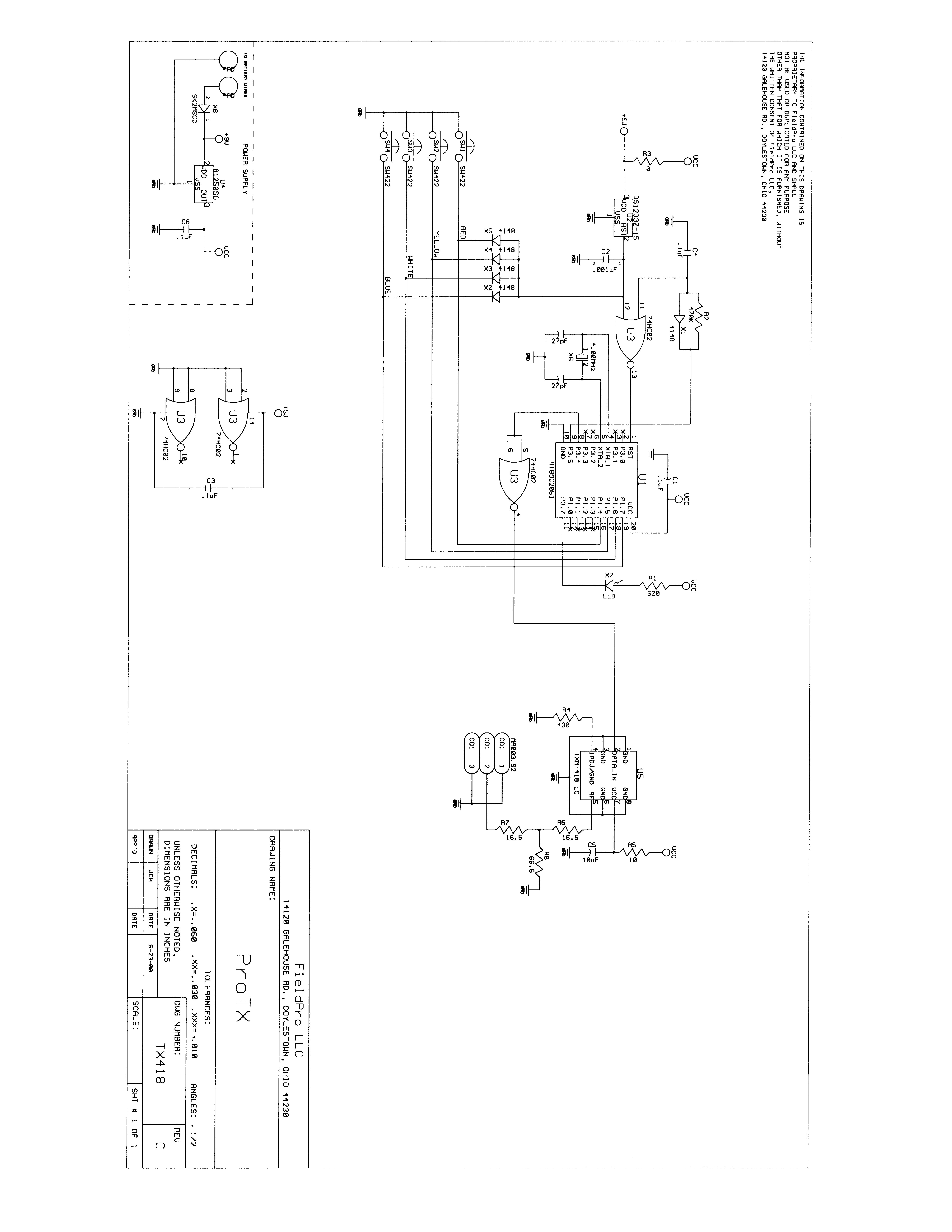
ProTX Block Diagram (FCC ID: O2CPROTX-1) Control Switches RF 418Mhz Transmitter Module Central Processing Un it Reset Circuit Reduced Height ¼ Wave Antenna +5V Power Supply
Operational Description
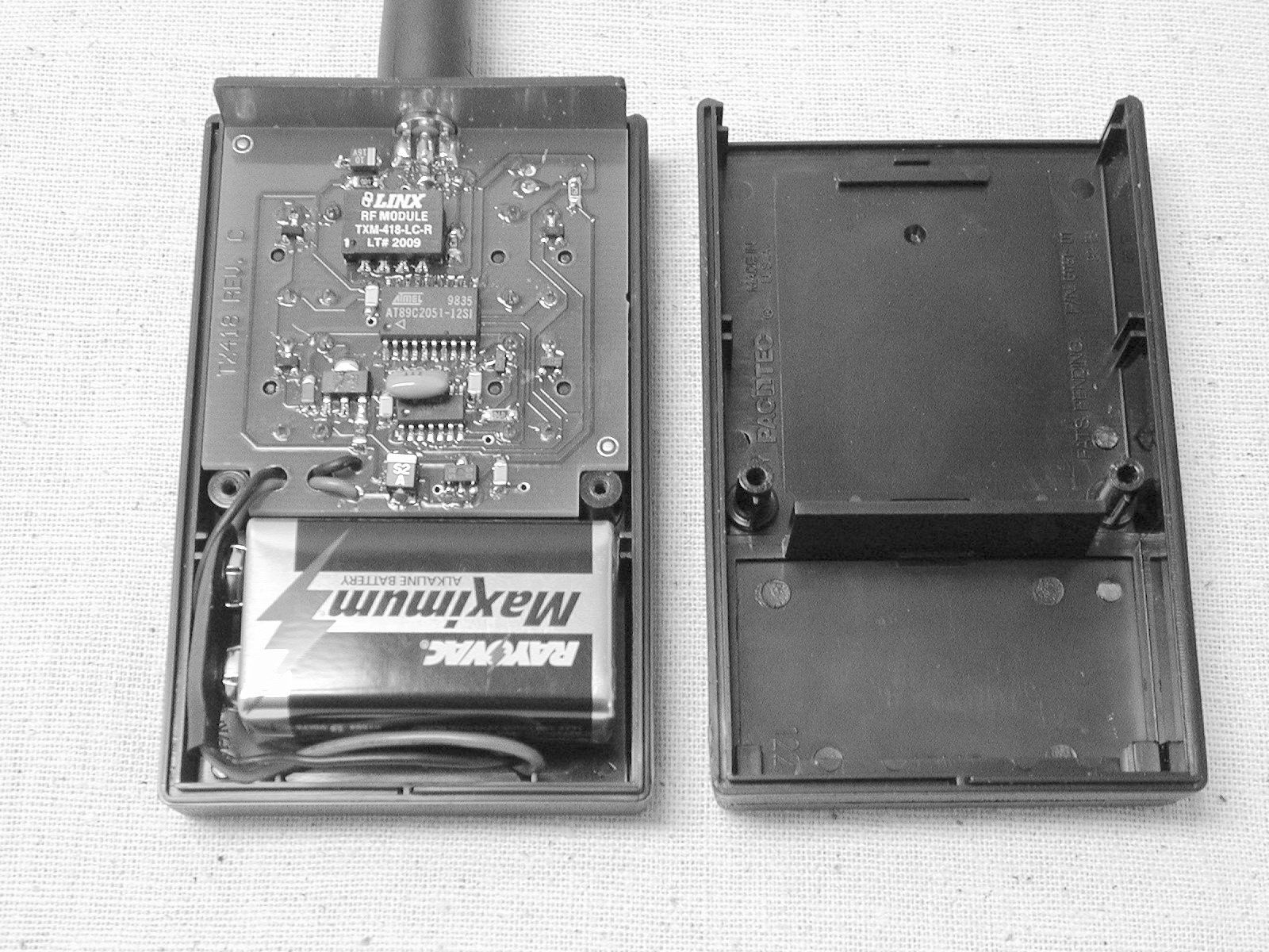
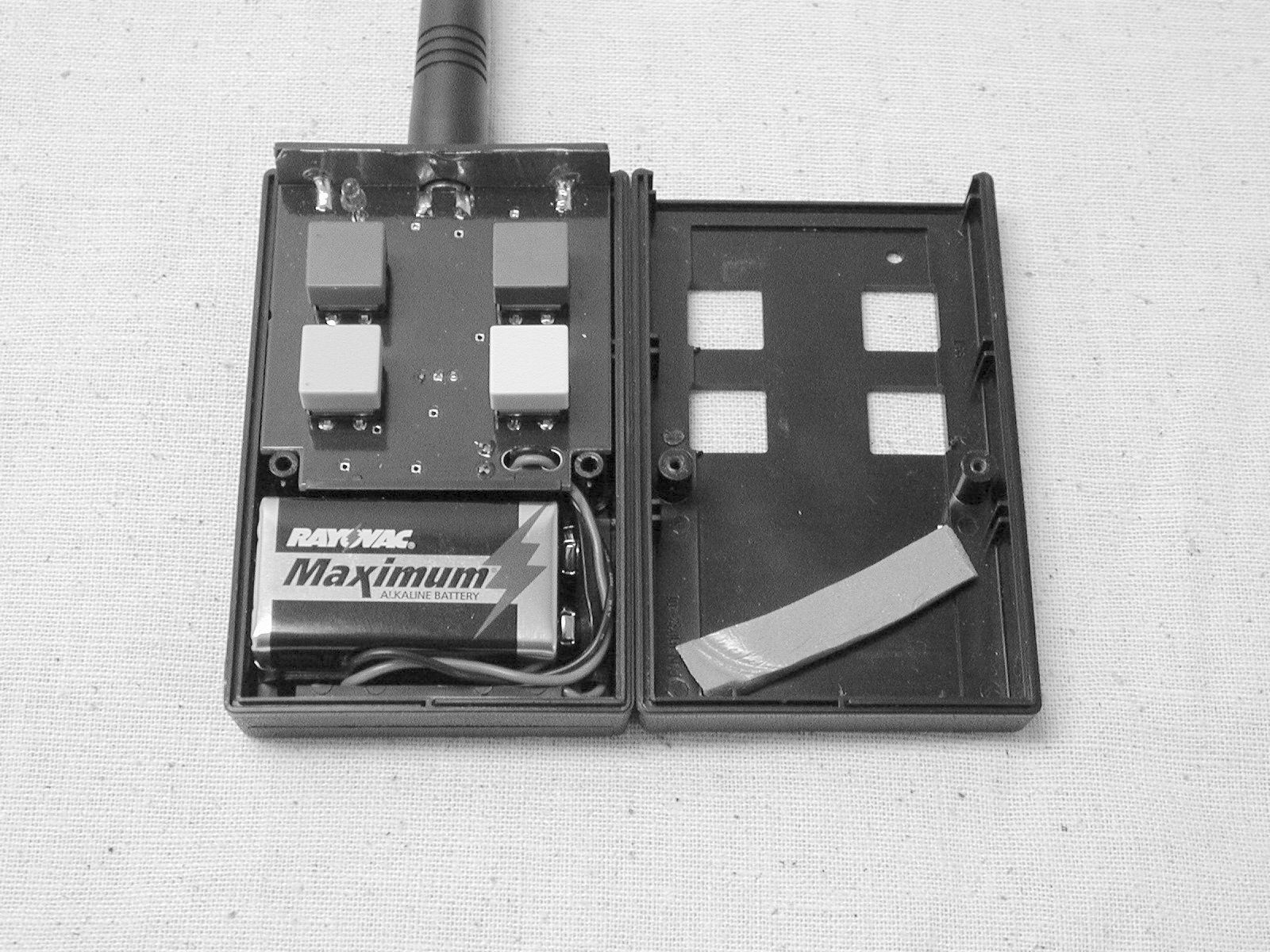
ProTX-1 Operational Description The FieldPro ProTX-1 transmitter is a low power communications device used to remotely control a game bird ejection device. The bird ejection device incorporates a receiver (FCC ID: O2CPRORX1) that is also subject to FCC Certification, which is discussed under a separate application. The FieldPro system is designed to aid in training of hunting dogs. The major objective of the FieldPro system is to train the dog to point at hidden game birds obscured in brush without disturbing the bird. The bird can be remotely released with this system if the dog approaches too quickly or closely, thus providing correct training reinforcement for the dog. The FieldPro ProTX-1 transmitter operates at 418 MHz and is designed around a Linx TXM-418-LC transmitter module. The transmitter is pulse modulated. The transmitter is equipped with four momentary contact push buttons to operate the transmitter. Each push button changes the pulse coding; thereby, the transmitter is capable of controlling four separate receivers. The transmitter operates only when a push button is depressed and ceases operation after the button is released. This characteristic allows the transmitter to meet FCC requirements of Part 15.231(a) regarding periodic operation. The transmitter is equipped with a rubberized (flexible) antenna. The antenna is detachable and replaceable by the end user. The antenna connector is a nonstandard so that a replacement must be ordered from FieldPro. The antenna connector is a reverse polarity SMA designed to meet FCC Part 15.203 antenna requirements.
Test Report
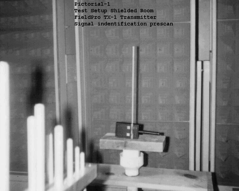
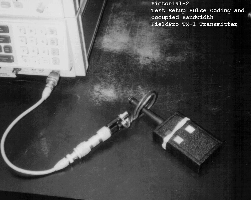
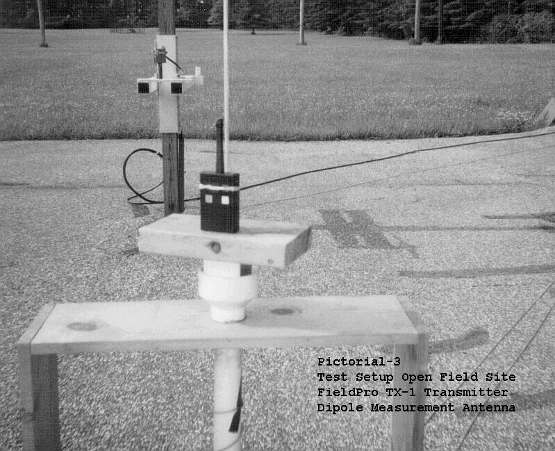
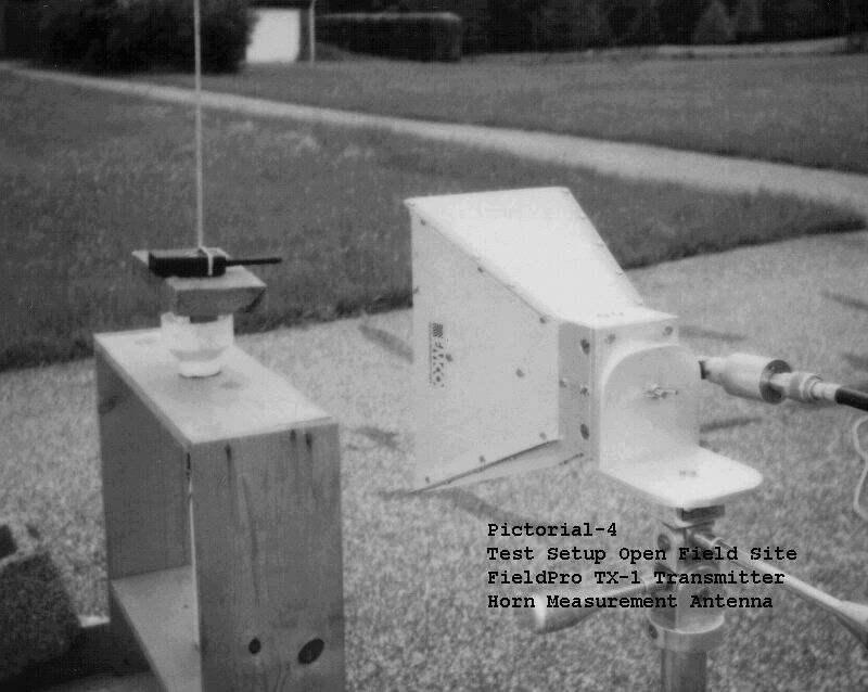
Smith Electronics, Inc. Electromagnetic Compatibility Laboratories Radio Frequency Measurement Report FCC Certification for Intentional Radiator on the FieldPro 418 MHz Handheld Transmitter Model: ProTX-1 FCC ID: O2CPROTX-1 May 31, 2000 Prepared by:Kenneth P. Klann NARTE Cert. EMC-001505-NE Prepared for:FieldPro, LLC. 14120 Galehouse Road Doylestown, OH 44230 Smith Electronics, Inc. 8200 Snowville Rd. Brecksville, Ohio 44141 Phone: (440) 526-4386 Fax: (440) 526-9205 Page 2 of 17 1.0 Objective: To perform radiated field intensity measurements to certify that the FieldPro model ProTX- 1 418 MHz handheld transmitter meets FCC intentional radiator requirements per CFR 47 1999, Part 15, Subpart C: • FCC Part 15.203, Antenna Requirement • FCC Part 15.231(a), Periodic Operation • FCC Part 15.231(b), Field Strength of Emissions • FCC Part 15.205(a)(b) & Part 15.209(a)-(e) Restricted Bands of Operation • FCC Part 15.231(c), Occupied Bandwidth 1.1 S ummary: The FieldPro model ProTX-1 (FCC ID: O2CPROTX-1) handheld transmitter has been examined and tested in accordance with FCC Part 15.31, 15.33, & 15.35, and ANSI C63.4-1992, and found compliant with FCC Parts 15.203, 15.231, and 15.205/15.209. The transmitter’s fundamental frequency (418 MHz) meets FCC Part 15.231(b) requirements limiting field strength by 0.56 dB. The worst case measurable harmonic frequency (2090 MHz) meet Part 15.231 by 30.41 dB. The most significant measured emission found in the Part 15.205/209 Restricted Bands was at 1672 MHz and remained 34.28 dB below the limit. Occupied Bandwidth per Part 15.231(c) was 62.0 KHz well within the prescribed limit of 1.045 MHz. Physical examination of the FieldPro ProTX-1 transmitter determined that the detachable antenna fitted with a reverse SMA connector met FCC Part 15.203 antenna connector requirements. Additionally, transmitter operation was manually actuated by depressing one of the push buttons and that the emissions ceased upon its release, thereby meeting FCC Part 15.231(a) requirements on Periodic Operation. Therefore, the FieldPro ProTX-1 (FCC ID: O2CPROTX-1) meets all requirements to be certified per requirements of FCC Part 15.201(b). I, Kenneth P Klann, an engineer at Smith Electronics, Inc., undertook the preparation of this report, performed all measurements contained herein, and attest to their accuracy. Kenneth P. Klann The results contained in this report describe the performance of the particular device tested and do not represent endorsement by any government agency. All intentional radiators must be certified by the FCC pursuant to the procedures in Part 2, Subpart J of CFR 47 1999 prior to marketing this device. This report must be reproduced in full. It can only be reproduced in part after obtaining written permission from Smith Electronics, Inc. Page 3 of 17 2.0 Administrative Information: Manufacturer:FieldPro, LLC. 14120 Galehouse Road Doylestown, Ohio 44230 Test Facility:Smith Electronics, Inc. 8200 Snowville Road Brecksville, Ohio 44141 Contacts:Jay Howard, President FieldPro, LLC. Phone: (330) 685-7705 (330) 262-1984 E276 Kenneth P. Klann, Test Engineer Smith Electronics, Inc. Phone: (440) 526-4386 Fax:(440) 526-9205 Test Dates:22 & 31 May 2000 2.1 Equipment Under Test: FieldPro handheld transmitter Model: ProTX-1 FCC ID: O2CPROTX-1 SN: Sample #1 Operating Frequency: 418 MHz, based on Linx TXM-418-LC transmitter module. Antenna: Linx reduced height ¼ wave rubberized, with reverse SMA termination. Linx PN: ANT-418-CW-HD Battery: 9 V rectangular 2.2 Modifications to EUT: None Page 4 of 17 2.3 Measurement Equipment: Hewlett Packard spectrum analyzer Type 8568B with 85680A RF section SN: 2216A02120 85662A display section SN: 2152A03686 85680A quasi-peak adapter SN: 2043A00350 Calibrated: 5/99 Used between: 30-1000 MHz Hewlett Packard spectrum analyzerType 8593EM SN: 3536A00147 Calibrated: 6/99 Used between: 1-4.2 GHz Singer Instrumentation interference receiverModel: NM-37/57 SN: 0366-06168 Calibrated: 4/99 Used between: 30-1000 MHz Hewlett Packard preamplifierType 8447D SN: 1726A01282 Gain: 26 dB Frequency range: .075-1700 MHz Hewlett Packard vector plotterType 7407A SN: 2308A39494 Biconical antennaEMCO model: 3104 Frequency range: 30-200 MHz (Shielded room) Log periodic antenna EMCO model: 3146 Frequency range: 200-1000 MHz (Shielded room) Tuned dipole antenna Stoddart model: 91598-2 Frequency range: 350-1000 MHz (Open field site) Horn Antenna EMCO Model: 3115 Frequency range: 1-18 GHz (Shielded room/open field site) Coaxial cable type RG-214/U8 meter length (shielded room <1GHz) 13 meter length (open field <1GHz) 1 meter length (shielded room/open field >1GHz) Page 5 of 17 3.1 Description: The FieldPro ProTX-1 transmitter is a low power communications device used to remotely control a game bird ejection device. The bird ejection device incorporates a receiver (FCC ID: O2CPRORX1) that is also subject to FCC Certification, which is discussed under a separate application. The FieldPro system is designed to aid in training of hunting dogs. The major objective of the FieldPro system is to train the dog to point at hidden game birds obscured in brush without disturbing the bird. The bird can be remotely released with this system if the dog approaches too quickly or closely, thus providing correct training reinforcement for the dog. The FieldPro ProTX-1 transmitter operates at 418 MHz and is designed around a Linx TXM-418-LC transmitter module. The transmitter is pulse modulated. The transmitter is equipped with four momentary contact push buttons to operate the transmitter. Each push button changes the pulse coding; thereby, the transmitter is capable of controlling four separate receivers. The transmitter operates only when a push button is depressed and ceases operation after the button is released. This characteristic allows the transmitter to meet FCC requirements of Part 15.231(a) regarding periodic operation. The transmitter is equipped with a rubberized (flexible…
Text truncated - open the document above for the full version.
Contact Information
Applicant
Jay Howard(Owner/Operator)
[email protected]330-658-7705
Technical Contact
FieldPro, LLCJay C Howard
[email protected]330-658-7705
14120 Galehouse Rd. · Doylestown, Ohio · United States
Non-Technical Contact
FieldPro, LLCJay C Howard
[email protected]330-658-7705
Test Firm
Smith Electronics, Inc.James Pollock
Technical Specifications
| # | Rule Parts | Frequency Range | Power Output |
|---|---|---|---|
| 1 | 15C | 414 MHz - 418 MHz | - |
Other Applications from FieldPro, LLC

O2CPRORX-1
Jul 19, 2000Remote Birdlauncher Receiver
Equipment Class
CYY - Communications Receiver used w/Pt 15 Transmitter