O2H8002001LPA800-Multi Carrier Power Amplifier
Bravo Tech Inc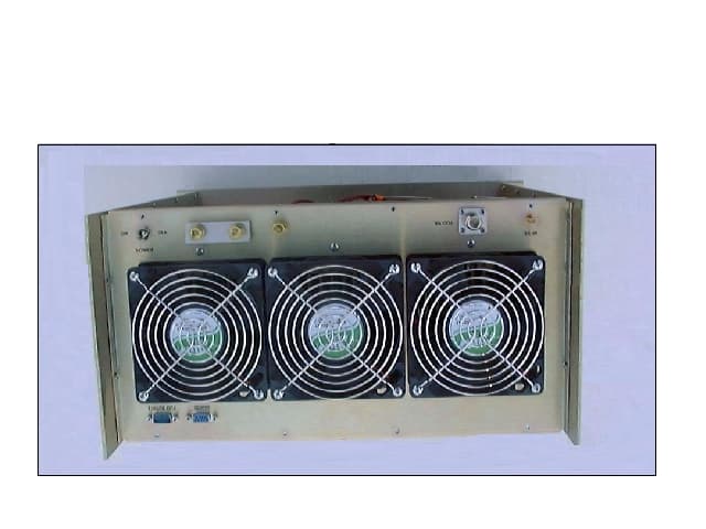
Click to zoom
Application Details
- Equipment Class
- AMP - Amplifier
- Date of Grant
- Nov 19, 2000
- Application Purpose
- Original Equipment
- Date of Application
- Nov 19, 2000
- Equipment Note
- LPA800-Multi Carrier Power Amplifier
- Frequency Range
- 850.00000000 - 870.00000000
- Company
- Bravo Tech Inc
- Country
- United States
Documents & Files
Document Text
Text extracted from the exhibit documents filed with the FCC. Open a document above to read the original.
Users Manual
Bravo Tech, Inc. FCC ID: O2H LPA800-200-1 BTI 1 Users Manual Bravo Tech, Inc. FCC ID: O2H LPA800-200-1 BTI 2 LPA800 Operating Manual Table of Contents SectionPage Number 1.General 1.1-Introduction ....................................................................................3 1.2-General Description...........................................................................3-4 1.3-Functional and Physical Specifications......................................................4 1.4-Equipment Changes.............................................................................4 2. Installation 2.1-Introduction......................................................................................5 2.2-Electrical Service Recommendations.........................................................5 2.3-Unpacking and Inspection......................................................................5 2.4-Installation Instructions........................................................................5 2.5-Amplifier Status.................................................................................6 3.Operating Instructions 3.1-Introduction......................................................................................7 3.2-Connections.......................................................................................7-9 3.3-Initial startup and Operating Procedure......................................................10 4.Principles of Operation 4.1-Introduction......................................................................................11 4.2-RF Input signal..................................................................................11 4.3-RF Output Load.................................................................................11 4.4-Amplifier Functional Description........................................................... 11-12 4.5-Amplifier Monitoring..........................................................................12 4.6-Amplifier Cooling..............................................................................129 5.Maintenance .......................................................................................................... 13 6.Table ...................................................................................................................... 4 Table 1 – Functional and Physical Specifications Bravo Tech, Inc. FCC ID: O2H LPA800-200-1 BTI 3 SECTION 1 GENERAL 1-1.INTRODUCTION. Congratulation on purchasing Bravo Tech’s advanced linear power amplifier. Our goal is to satisfy you with our RF technology expertise, offering the best product with unsurpassed quality, performance and at the best price. In fact, a strong background in wireless communication technologies enables Bravo Tech to provide highly integrated products with the most advanced features in the industry. Our commitment to quality and product excellence makes Bravo Tech a strong contender in the industry. Bravo Tech designs, manufactures, and markets the most advanced Linear Power Amplifiers for use in wireless communication systems. Our Linear Power Amplifiers are designed with the most advanced RF and digital control technology. Our focus on high-end power amplifiers at affordable price results in total commitment to offering state of the art products to meet the growing needs of today‘s exploding wireless communication market. We consider "value" a requirement in every facet of a product, not just a feature. When comparing Power Amplifiers, consider all the essential factors in your decision. Price and performance characteristics such as distortion specifications, flexibility, reliability and design parameters are critical. And not least of all the warranty- will the manufacturer stand behind their products? Bravo Tech will consistently outpace the competition in every category. This manual contains information and procedures for installation, operation, and maintenance of the LPA800 Series multichannel feed-forward linear power amplifier system. The manual is organized into five sections as follows: Section 1. General Description Section 2. Installation Section 3. Operating Instructions Section 4. Principles of Operation Section 5. Maintenance 1-2.GENERAL DESCRIPTION The LPA800 Series multichannel feed-forward linear power amplifier is specially designed for trunking systems, featuring bandwidth up to 20 MHz and output power up to 200W per system. Our Power Amplifiers are designed with our advanced RF and digital control technology. They provide unsurpassed power, linearity, efficiency, and system flexibility in trunking, cellular, and wireless local loop systems. The intelligent digital control system constantly fine-tunes the amplifiers to ensure optimum operation over a wide variety of electrical and environmental conditions. The amplifiers can be fed up to 16 channels and meet all FCC requirements. The system is designed to provide trouble free operation with minimum maintenance. The LED- based operational status and fault indicators help minimize downtime. The turn-on and turn-off sequences of voltages are fully automatic, as is overload protection, making the amplifier Bravo Tech, Inc. FCC ID: O2H LPA800-200-1 BTI 4 virtually impervious to failures caused by system problems. RF I/O and D.C. Power are connected to the rear panel of the amplifier. The rear panel also has the serial port connectors that interface with the host control system. The system status connector allows the host system to monitor performance of the amplifier. The front panel of the amplifier equipped with fault indicators. D.C. power for the amplifier system is +27 Vdc. Cooling for the amplifier is provided by three fans mounted on the rear of the system. The fans draw outside air through the front of and exhaust hot air through the rear of the rack. 1-3.FUNCTIONAL AND PHYSICAL SPECIFICATIONS Functional and physical specifications for the amplifier system are listed in Table 1. PARAMETERSPECIFICAT…
Text truncated - open the document above for the full version.
Cover Letter(s)
Bravo Tech, Inc. 4260 Cerritos Ave. Los Alamitos CA 90720 Phone: 714-952-8324Fax: 714-952-0107 August 24, 2000 Subject: Confidentiality Request Dear FCC: Please see the attached files that are required for the application. Because the LPA800 Multi-Carrier Power Amplifier model was designed by Bravo Tech, Inc., we request to have the Schematics section (attached under the file name Schematics.doc ) be held confidential. This Schematics file includes of the following specific information: ! LPA800 Schematics - Circuitry ! LPA800 PCB Layout Please let us know if you need any additional information. Best Regards, Bailey Zheng President BTI
Cover Letter(s)
Non-Conformities (Ref # E00-000488-1) FCC ID:02H8002001 Item 1: Your address on the 731 form differs from the address that is registered with the FCC. Please submit a letter to the FCC regarding your address change in accordance with section 2.929 and/or correct the 731 form accordingly. We have already submitted address change to FCC Item 2: Please provide an explanation of how the emission type F8E was derived. The test report indicates an emission type of F1E. Please advise of correct emission type. The system is used for FM transmition (F). The system support more then one carrier (8). The system is for voice telephony application (E). So the correct emission type is F8E Item 3: The photos provided do not supply sufficient detail. Please provide close up photos of the PCB’s showing component placement. The detail are supplied in the PCB section Item 4: Please explain why a limit of –59dBc was used for the antenna conducted and radiated measurements? This limit does not correspond with the limit stated in 90.210. Please show the calculations. The input signal plot and the output signal plot are indicating mainly the delta marker values and the gain. While the output power of the amplifier is read accurately in the power meter, the amplifier was first adjusted to 200W according to the power meter labeling "15, 16" in the page 8 of the filing report. Then, the output plot was taken from the spectrum analyzer. The important information of the output plot is the delta marker value, which is -60.74 dB. Since the FCC limit value should be - 59dBc ( 4 carriers, 50W/carrier), the amplifier satisfies the FCC requirement. Item 5: It is acceptable for an amplifier to have a listed frequency range of 850 to 870 MHZ. The FCC requires that a bandwidth plot for each channel which shows the input signal and output signal for the worst case across the operating band be submitted. Input plots of low, middle and high were provided. Test additional test data files. Item 6: If applicable please provide the tune-up procedure over the power range, or at the specific operating power levels. The system is not user serviceable.
External Photos
Bravo Tech, Inc. FCC ID: O2H LPA800-200-1 BTI 1 External Photos Bravo Tech, Inc. FCC ID: O2H LPA800-200-1 BTI 2 P HOTOGRAPHS AND/OR D RAWINGS S HOWING C ONSTRUCTION T ECHNIQUES Photo: EUT Overall View Bravo Tech, Inc. FCC ID: O2H LPA800-200-1 BTI 3 Photo: EUT Top View Bravo Tech, Inc. FCC ID: O2H LPA800-200-1 BTI 4 Photo: EUT Front View Bravo Tech, Inc. FCC ID: O2H LPA800-200-1 BTI 5 Photo: EUT Rear View. Bravo Tech, Inc. FCC ID: O2H LPA800-200-1 BTI 6 Photo: EUT Side View Bravo Tech, Inc. FCC ID: O2H LPA800-200-1 BTI 7 Photo: EUT Bottom View FCC ID: O2H LPA800-200-1 8
ID Label/Location Info
Bravo Tech, Inc. FCC ID: O2H LPA800-200-1 BTI 1 ID Label / Location Info Bravo Tech, Inc. FCC ID: O2H LPA800-200-1 BTI 2 Bravo Tech, Inc. FCC ID: O2H LPA800-200-1 BTI 3 Bravo Tech, Inc. FCC ID: O2H LPA800-200-1 BTI 4
Internal Photos
Bravo Tech, Inc. FCC ID: O2H LPA800-200-1 BTI 1 Internal Photos Bravo Tech, Inc. FCC ID: O2H LPA800-200-1 BTI 2 Photo: EUT Top View (with cover removed) Bravo Tech, Inc. FCC ID: O2H LPA800-200-1 BTI 3 Photo: EUT Bottom View (with cover removed) Bravo Tech, Inc. FCC ID: O2H LPA800-200-1 BTI 4 Photo: EUT PCB Circuitry Layout Bravo Tech, Inc. FCC ID: O2H LPA800-200-1 BTI 5 Bravo Tech, Inc. FCC ID: O2H LPA800-200-1 BTI 6 Bravo Tech, Inc. FCC ID: O2H LPA800-200-1 BTI 7 Bravo Tech, Inc. FCC ID: O2H LPA800-200-1 BTI 8 Bravo Tech, Inc. FCC ID: O2H LPA800-200-1 BTI 9 Bravo Tech, Inc. FCC ID: O2H LPA800-200-1 BTI 10 Bravo Tech, Inc. FCC ID: O2H LPA800-200-1 BTI 11 Bravo Tech, Inc. FCC ID: O2H LPA800-200-1 BTI 12 Bravo Tech, Inc. FCC ID: O2H LPA800-200-1 BTI 13
Internal Photos
LPA800 PCB Layout
Operational Description
2. Technical Description Type of Emission 20K0F1E Frequency Range 850 ∼ 870 MHz Range of Operating Power 100 ∼ 200W Maximum output Power Level 200W Maximum Specified Output Power Rating Location Dependant per Part 90 Subpart S Final Stage Amplifier DC Voltage, Current Voltage: 27.0 Vdc, Current: 51 Amps 2.1 Function of All Active Circuit Devices Board-TSLPA900-00009-2 Pre-Driver • D3-D10: varactor diodes comprising part of voltage controlled phase shifter • D1-D2: PLN diodes comprising part of voltage variable attenuator (VVA) • Q1:current booster for VVA driver on DCXX-00101 • U1: Detector for RF input power level • U4: hybr id RF amplifier, driver for Q3 • Q3: Pre-driver output stage • U2-U3: voltage regulators Board-TSLPA900-00011-2 Pre-Error Amp • D3-D10: varactor diodes comprising part of voltage controlled phase shifter • D1-D2: PIN diodes comprising part of voltage variable attenuator (VVA) • U1: Detector for first loop cancellation power level • Q1-Q2: Rf amplifiers, pre –drivers for CP1 on XM120-006-1 • U2: voltage regulator Board-PSXXX-001-1 Power Conditioner • Q1-Q8: relay drivers • D1-D4: relay flyback diodes • U1-U3: voltage regulators • U4-U5: voltage inverters Board-XM120-006-1 Error Amp • U1: 120W Hybrid power amplifier module, output stage for error amp • U2: voltage regulator Board-DCXX-001-1 Controller • U1: Op-amp • U2: voltage regulator • U3: 8-bit microcontroller • U4: voltage inverter • U5-U6: voltage regulators • U7-U8: Op-amps • U9: voltage regulator • U10: D-A converter • Q2: current boost for VVA on pre-error amp Board-COMSXXX-001 Driver • U1: Hybrid RF amplifier, driver for main amp
Test Report
Bravo Tech, Inc. FCC ID: O2H-800-200-1 BTI 1 EMC Measurement / Technical Report Test Specification: FCC Part 90, Private Land Mobile Radio Services Equipment Authorization: Certification Manufacturer: Bravo Tech, Inc. Equipment Under Test: LPA800 Multi-Carrier Power Amplifier Test Report No.: BRAVO 0000001 Document History RevisionIssue DateAffected Pages Description of Modifications Revised By Approved By 027 November, 2000 Initial release Bravo Tech, Inc. FCC ID: O2H-800-200-1 BTI 2 EMC Measurement / Technical Report Document No.: 000001 Bravo Tech, Inc. LPA800 Multi-Carrier Power Amplifier FCC ID: O2H8002001 W RITTEN B Y R EVIEWED B Y R EVIEWED B Y Dick Chiang EMC Consulting Engineer Minh Nguyen Technical Manager Bailey Zheng President Test PersonnelTest Dates Dick P. Chiang26, 27, 29 April & 18, 20 May 2000 Test Facility Address City, State, Zip Code Country Phone Fax Garwood Laboratories Bravo Tech, Inc. 565 Porter Way 4260 Cerritos Ave. Placentia, CA 92870 Los Alamitos, CA 90720 USA USA (714) 572-2027 (714) 952-8324 (714) 572-2025 (714) 952-0107 This report may be reproduced in full, partial reproduction may only be made with the written consent of the manufacturer. The results in this report apply only to the equipment tested. This report may not be used to claim product endorsement any agency of the U.S. government. Bravo Tech, Inc. FCC ID: O2H-800-200-1 BTI 3 TABLE OF CONTENTS (This document contains a total of 31 pages [excluding] attachments.) MEASUREMENT / TECHNICAL REPORT SUMMARY..................................................................................... 4 1. GENERAL INFORMATION ........................................................................................................................ 5 1.1 Product Description.......................................................................................................... 5 1.2 Tested System Details......................................................................................................5 2. TECHNICAL DESCRIPTION...................................................................................................................... 6 2.1 Function of All Active Circuit Devices................................................................................. 6 2.2 Circuit Diagram ................................................................................................................ 6 2.3 Instruction Manual(s)........................................................................................................ 7 3. PRODUCT LABELING...............................................................................................................................8 3.1 FCC ID Label................................................................................................................... 8 3.2 Location of Label on EUT.................................................................................................. 8 3.3 Information to User ........................................................................................................... 8 4. SYSTEM TEST CONFIGURATION............................................................................................................ 9 4.1 Justification...................................................................................................................... 9 4.2 EUT Exercise Software/Equipment .................................................................................... 9 4.3 Special Accessories .........................................................................................................9 4.4 Equipment Modifications................................................................................................... 9 4.5 Configuration of Tested System.............................................................................. 10,11,12 5. TEST DATA .............................................................................................................................................13 5.1 RF Power Output.............................................................................................................13 5.2 Modulation Characteristics...............................................................................................14 5.3 Occupied Bandwidth........................................................................................................15 5.4 Spurious Emissions at Antenna Terminals........................................................................16 5.5 Radiated Spurious Emissions...........................................................................................17 5.6 Conducted Emissions at Power lines................................................................................18 5.7 Frequency Stability..........................................................................................................19 6. PHOTOGRAPHS AND/OR DRAWINGS SHOWING CONSTRUCTION TECHNIQUES.................................20 6.1 EUT Overall View............................................................................................................20 6.2 EUT Top View............…
Text truncated - open the document above for the full version.
Contact Information
Applicant
Bailey Zheng(COO)
Technical Contact
Bravo TechMinh Nguyen
[email protected]714-952-8324
4260 Cerritos Ave. · Los Alamitos, California · United States
Non-Technical Contact
Bravo TechVictoria Nguyen
[email protected]714-952-8324
Test Firm
Garwood Laboratories, Inc.Jason Armstrong
714-572-2027Fax: 714-572-2025
Technical Specifications
| # | Rule Parts | Frequency Range | Power Output | Emission |
|---|---|---|---|---|
| 1 | 90 | 850 MHz - 870 MHz | 200 W | F8E |