O2IMCB-RT-1601Color Weather and Search and Rescue Radar
Telephonics Corporation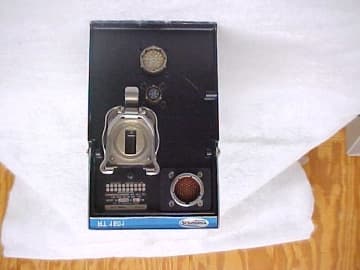
Click to zoom
Application Details
- Equipment Class
- TNB - Licensed Non-Broadcast Station Transmitter
- Date of Grant
- Oct 03, 2002
- Application Purpose
- Original Equipment
- Date of Application
- Sep 17, 2002
- Equipment Note
- Color Weather and Search and Rescue Radar
- Frequency Range
- 9300.00000000 - 9500.00000000
- Company
- Telephonics Corporation
- Country
- United States
Documents & Files
Document Text
Text extracted from the exhibit documents filed with the FCC. Open a document above to read the original.
Users Manual
MAINTENANCE MANUAL RT-1601 RECEIVER-TRANSMITTER 815 Broadhollow Road 631-755-7000 Farmingdale, N.Y. 11735 FAX 631- 755-7200 1 SECTIO N 1 DESCRIPTIO N AND OPERATIO N 1. General This section provides a general description of the circuit functions and operation of the RT-1601 Receiver-Transmitter. Subsequent information includes operation, equipment part numbers, block diagram discussion, and theory of operation. NOTE: General information for the RDR-1600 Weather Radar System, such as system leading particulars, system operation, and a system operational check is contained in the Radar System Installation Manual, TM106601 Maintenance information for the DA-1203A Radar Antenna is contained in PART 1 of the Weather vision System Antennas Maintenance Manual, I.B. 21000A. 2. Operation The receiver-transmitter (R-T) operates by emitting very short, intense pulses of microwave energy, which are reflected within the range of the radar system. A portion of the radiated energy, reflected by an object having reflective characteristics, is returned along the same general path to the aircraft where it is received and converted into digital data that is representative of the target size. The digital data is then routed to the radar indicator where it is processed to give a visual presentation of the target. The receiver-transmitter is housed in a short ½ ATR form factor case. Overall dimensions can be found on the receiver–transmitter outline drawing. The mounting tray for the R-T unit, which is designed for front loading, provides positive positioning and holding of the unit to the aircraft. The mounting tray is mounted to the aircraft, and the R-T unit can easily be removed and replaced for servicing. Depending upon installation requirements, different models of the mounting tray are available. For ease of maintenance, all circuits are contained on plug-in boards. These PC boards are interconnected by way of a ribbon cable, which makes all connections between PC boards. An interconnect PC board replaces the conventional wiring harness arrangement. The RT-1601 uses a frequency trimmable magnetron for reliable interrogation of beacon transponders; input frequency in an accurate 9375 +5 MHz. The RT-1601 functions as short-range pulse radar for high resolution ground mapping (search) and a long range pulse for conventional weather. The reflected signal is received by the system’s sector scanning antenna, amplified and digitized by the R-T unit, and then routed to the radar indicator. All system power requirements are routed via the R-T unit to the radar indicator and the antenna. 3. Equipment Part Numbers Table 1 lists the TELEPHONICS part number for the RT-1601 Receiver-Transmitter. A brief description of the unit is also provided. Table 2 lists the major assemblies in the RT-1601 MAINTENANCE MANUAL RT-1601 RECEIVER-TRANSMITTER 815 Broadhollow Road 631-755-7000 Farmingdale, N.Y. 11735 FAX 631- 755-7200 2 TELEPHONICS PART NUM BER TYPEDESCRIPTIO N 379-2011-001RT-1601Provides X-band output to sector-scanning antenna. Reflected signal is amplified by receiver, digitized, and routed to the radar indicator. The magnetron is frequency trimmable and is designed to operate at 9375 +5 MHz to permit reliable triggering of the beacon transponder. Operating parameters permit optimum performance in each of the five modes (3 search modes, weather mode, and beacon mode) complies with TSO certification C102 for ground target approach to within 1000 feet. Table 1. RT-1601 Receiver-Transmitter Part Numbe rs MODULE OR ASSEMBLY NAME PART NUM BERREFERENCE SERIES CONNECTORS Interconnect (Mother) Board3606464-0501 3606464-0502 1200J1204, J1205, J1208, J1217, J1218 Front Panel Connector Board3606465-05011100P1101, P1103 Receiver Board3606458-05012000J2006, J2016, P2020, P2021 Mode-Decode Board379-2040-0018000J8023 Power Supply Assembly4007721-05045000J5011 PS Control Board Assembly4007714-05015000 Power Supply Module4007715-05015000 Local Oscillator Assembly4007932-05016000P6012 Beacon Amplifier Assembly Beacon Receiver Module 3606473-05017000P7016, P7019 Table 2:RT-1601 Subassemblies and Connectors 4. Block Diagram Discussion (Refer to figure 1) A. Waveform Sy nc hro ni zatio n a nd Tra nsmitter Functio n A crystal-controlled oscillator located in theMode Decode board generates basic synchronization signals for the radar system. The clock frequency is counted down to 1536 Hz for range selections of 10 NM or less in search-one and search-two modes. For all other ranges and modes the clock frequency is counted down to 200 Hz. Either the 1536 Hz or the 200 Hz system trigger keys the transmitter and provides other timing functions. The system trigger also keys the suppression pulse generator to turn off sensitive equipment when the R-T unit transmits. The System trigger is applied to the timing circuit, which controls the AFC gate, the STC-function gate, the AFC-AGC trigger, and the test-pattern-generator circuits. The system trigger is buffered and routed to the modulator driver MAINTENANCE MANUAL RT-1601 RECEIVER-TRANSMITTER 815 Broadhollow Road 631-755-7000 Farmingdale, N.Y. 11735 FAX 631- 755-7200 3 where selection of either the modulator short pulse (0.2 usec) or the modulator long pulse (2.35 usec) is selected. Pulse width selection is made depending on the operation mode selected on the radar indicator. Modulator long pulse is selected for modes using a 200-Hz trigger; modulator short pulse is selected for modes using an 1536 Hz trigger. With either modulator pulse, a negative-going, 330- volt, 110-ampere pulse is applied to the pulse transformer. The pulse transformer supplies the magnetron with a 5.5 kV, 4.5 A, negative-going pulse that causes the magnetron to oscillate at its 9375 MHz resonant frequency. A 10-kW nominal peak power RF output pulse is generated by the magnetron and is directed through the four-port, E-plane circulator to the radar antenna. B. Receiver Function The R-T unit employs a dual-conversion, superhe…
Text truncated - open the document above for the full version.
Users Manual
TM106601 (7/01) RADAR 1600RADAR 1600 WEATHER RADAR SYSTEMWEATHER RADAR SYSTEM INSTALLATION MANUALINSTALLATION MANUAL July 2001 Prepared by: TELEPHONICS CORPORATION 815 Broad Hollow Road Farmingdale, New York 11735 USA TM106601 (7/01) COMMAND SYSTEMS DIVISION RDRRDR--16001600 WEATHER RADAR SYSTEMWEATHER RADAR SYSTEM INSTALLATION MANUALINSTALLATION MANUAL Copyright © 1995/2001 Telephonics Corporation Publication No.: TM106601 All Rights Reserved Printed in U.S.A. Telephonics Corporation, Command Systems Division (CSD) 815 Broad Hollow Road, Farmingdale, New York 11735 Telephone: (877) 517-2327 Fax: (877) 755-7701 This publication may not be reproduced in part or in whole without the expressed written consent of Telephonics Corporation. TM106601_(7/01) FMi USE OR DISCLOSURE OF DATA CONTAINED ON THIS PAGE IS SUBJECT TO THE RESTRICTION ON THE TITLE PAGE OF THIS DOCUMENT. COMMAND SYSTEMS DIVISION Maintain prescribed safe distance when standing in front of radiating antenna. Never expose eyes or any part of the body to an unterminated wave guide. CAUTION TM106601_(7/01) FMii USE OR DISCLOSURE OF DATA CONTAINED ON THIS PAGE IS SUBJECT TO THE RESTRICTION ON THE TITLE PAGE OF THIS DOCUMENT. COMMAND SYSTEMS DIVISION MAXIMUM PERMISSIBLE EXPOSURE LEVEL (MPEL) In order to avoid the envelope in which the radiation level exceeds the U.S. Government standard of 1 mW per square centimeter, all personnel should remain beyond the distance indicated in the illustration below. The distance to the MPEL boundary is calculated upon the basis of the largest antenna available with the RDR-1600 system, rated output power of the transmitter and in the non- rotating or boresight position of the antenna. With a scanning beam, the power density at the MPEL boundary is significantly reduced. TM106601_(7/01) FMiii USE OR DISCLOSURE OF DATA CONTAINED ON THIS PAGE IS SUBJECT TO THE RESTRICTION ON THE TITLE PAGE OF THIS DOCUMENT. COMMAND SYSTEMS DIVISION INSTALLATION MANUAL RDR-1600 WEATHER RADAR SYSTEM AC 20-68B DATE 8/8/80 DEPARTMENT OF TRANSPORTATION Federal Aviation Administration Washington, D.C. ————————————————————————————————— ————————————————————————————————— Subject: RECOMMENDED RADIATION SAFETY PRECAUTIONS FOR GROUND OPERATION OF AIRBORNE WEATHER RADAR 1. PURPOSE . This circular sets forth recommended radiation safety precautions to be taken by personnel when operating airborne weather radar on the ground. 2, CANCELLATION . Ac 20-68A, dated April 11, 1975, is canceled. 3. RELATED READING MATERIAL . a. Barnes and Taylor, Radiation Hazards and Protection (London: George Nevnes Limited, 1963). P. 211. b. U.S. Department of Health, Education and Welfare, Public Health Service, Consumer Protection and Environmental Health Service, “Environmental health microwave, ultraviolet radiation and radiation from lasers and television receivers – An Annotated Bibliography,” FS 2.300: RH-35, Washington, U.S. Government Printing Office, pp. 56-57. c. Mumford, W.W., “Some technical aspects of microwave radiation hazards,” Proceedings of the IRE, Washington, U.S. Government Printing Office, February 1961, pp. 427-447. 4. BACKGROUND . Dangers from ground operation of airborne weather radar include the possibility of human body damage and ignition of combustible materials by radiated energy. Low tolerance parts of the body include the eyes and testes. 5. PRECAUTIONS . Management and supervisory personnel should establish procedures for advising personnel of dangers from operating airborne weather radars on the ground. Precautionary signs should be displayed in affected areas to alert personnel of ground testing. a. GENERAL . (1) Airborne weather radar should be operated on the ground only by qualified personnel. ————————————————————————————————— TM106601_(7/01) FMiv USE OR DISCLOSURE OF DATA CONTAINED ON THIS PAGE IS SUBJECT TO THE RESTRICTION ON THE TITLE PAGE OF THIS DOCUMENT. COMMAND SYSTEMS DIVISION INSTALLATION MANUAL RDR-1600 WEATHER RADAR SYSTEM AC 20-68B 8/8/80 (2) Installed airborne radar should not be operated while the aircraft is in a hangar or other enclosure unless the radar transmitter is not operating, or the energy is directed toward an absorption shield which dissipates the radio frequency energy. Otherwise, radiation within the enclosure can be reflected throughout the area. b. Body Damage. To prevent possible human body damage, the following precautions should be taken: (1) Personnel should never stand nearby and in front of a radar antenna which is transmitting. When the antenna is not scanning, the danger increases. (2) A recommended safe distance from operating airborne weather radars should be established. A safe distance can be determined by using the equations in Appendix 1 or the graphs of figures 1 and 2. This criterion is now accepted by many industrial organizations and is based on limiting exposure of humans to an average power density not greater than 10 milliwatts per square centimeter. (3) Personnel should be advised to avoid the end of an open waveguide unless the radar is turned off. (4) Personnel should be advised to avoid looking into a waveguide, or into the open end of a coaxial connector or line connector to a radar transmitter output, as severe eye damage may result. (5) Personnel should be advised that when high power radar transmitters are operated out of their protective cases, X-rays may be emitted. Stray X-rays may emanate from the glass envelope type pulser, oscillator, clipper, or rectifier tubes, as well as magnetrons. c. Combustible Materials . To prevent possible fuel ignition, an installed airborne weather radar should not be operated while an aircraft is being refueled or defueled. M.C. BEARD Director of Airworthiness TM106601_(7/01) FMv USE OR DISCLOSURE OF DATA CONTAINED ON THIS PAGE IS SUBJECT TO THE RESTRICTION ON THE TITLE PAGE OF THIS DOCUMENT. COMMAND SYSTEMS DIVISION INSTALLATION MANUAL RDR-1600 WEATHER RADAR SYSTEM AC NO: 43-14 DATE: 2/24/77 DEPARTMENT OF TRANSPORTATION F…
Text truncated - open the document above for the full version.
Users Manual
Pilot’s GuideRDR-1600 Color Weather and Search and Rescue Radar TM106101August 2001 Command Systems Division TM106101(8/01)RDR-1600 Pilot’s Guidei TABLE OF CONTENTS PARAGRAPHTITLEPAGE 1.0 INTRODUCTION . . . . . . . . . . . . . . . . . . . . . . . . . . . .1 2.0SYSTEM CONFIGURATION . . . . . . . . . . . . . . . . . . .2 2.1ANTENNA AND RECEIVER-TRANSMITTER . . . . . . .3 2.2RADAR DISPLAY INDICATOR . . . . . . . . . . . . . . . . . .4 3.0 OPERATIONAL CONTROLS . . . . . . . . . . . . . . . . . . .5 3.1FUNCTION SELECTOR – CP-113K CONTROL PANEL . . . . . . . . . . . . . . . . . . . . . . . . .5 3.2ANTENNA CONTROLS . . . . . . . . . . . . . . . . . . . . . . .6 3.3DISPLAY CONTROLS . . . . . . . . . . . . . . . . . . . . . . . .6 3.4PRIMARY MODE SELECTORS . . . . . . . . . . . . . . . . .6 3.5SECONDARY MODE SELECTOR AND GAIN CONTROLS . . . . . . . . . . . . . . . . . . . . . . . . . . . . . .8 3.6ALPHANUMERICS . . . . . . . . . . . . . . . . . . . . . . . . . .9 4.0PREFLIGHT (PFT) . . . . . . . . . . . . . . . . . . . . . . . . . .10 4.1PREFLIGHT WARNING . . . . . . . . . . . . . . . . . . . . . .10 5.0THEORY OF OPERATION . . . . . . . . . . . . . . . . . . . .11 5.1GENERAL . . . . . . . . . . . . . . . . . . . . . . . . . . . . . . . .11 5.2RADAR PRINCIPLES . . . . . . . . . . . . . . . . . . . . . . .12 5.3WEATHER RADAR PRINCIPLES . . . . . . . . . . . . . . .13 5.4RADAR REFLECTIVITY . . . . . . . . . . . . . . . . . . . . . .14 5.5WEATHER DISPLAY CALIBRATION . . . . . . . . . . . .15 5.6WEATHER ATTENUATION COMPENSATION . . . . .16 6.0WEATHER OPERATIONS . . . . . . . . . . . . . . . . . . . .18 6.1WEATHER MODE – WX . . . . . . . . . . . . . . . . . . . . .18 6.2WEATHER ALERT MODE – WXA . . . . . . . . . . . . . .19 6.3TARGET ALERT . . . . . . . . . . . . . . . . . . . . . . . . . . .19 6.4WEATHER MAPPING AND INTERPRETATION . . . .20 6.5OBSERVING WEATHER . . . . . . . . . . . . . . . . . . . . .20 6.5.1Thunderstorms and Turbulence . . . . . . . . . . . . . . . .21 6.5.2Tornadoes . . . . . . . . . . . . . . . . . . . . . . . . . . . . . . . .22 6.5.3Hail . . . . . . . . . . . . . . . . . . . . . . . . . . . . . . . . . . . . .23 6.5.4Icing . . . . . . . . . . . . . . . . . . . . . . . . . . . . . . . . . . . . .24 6.5.5Snow . . . . . . . . . . . . . . . . . . . . . . . . . . . . . . . . . . . .24 6.5.6Lightning and Static Discharges . . . . . . . . . . . . . . . .24 6.5.7Range Resolution . . . . . . . . . . . . . . . . . . . . . . . . . . .25 6.5.8Azimuth Resolution . . . . . . . . . . . . . . . . . . . . . . . . .25 6.5.9Indicator Resolution . . . . . . . . . . . . . . . . . . . . . . . . .26 6.5.10Short Range Displays . . . . . . . . . . . . . . . . . . . . . . . .27 6.6PATH PLANNING . . . . . . . . . . . . . . . . . . . . . . . . . . .28 6.6.1Path Planning Considerations . . . . . . . . . . . . . . . . . .28 TM106101(8/01)RDR-1600 Pilot’s GuideiiiiiRDR-1600 Pilot’s GuideTM106101(8/01) TABLE OF CONTENTS (CONT.) PARAGRAPHTITLEPAGE 7.0SEARCH OPERATIONS . . . . . . . . . . . . . . . . . . . . .31 7.1GROUND MAPPING . . . . . . . . . . . . . . . . . . . . . . . .31 7.1.1Looking Angle . . . . . . . . . . . . . . . . . . . . . . . . . . . . .32 7.1.2Other Aircraft . . . . . . . . . . . . . . . . . . . . . . . . . . . . . .33 7.2SEARCH MODE . . . . . . . . . . . . . . . . . . . . . . . . . . .33 7.3DIFFERENCE BETWEEN WEATHER AND SEARCH MODES . . . . . . . . . . . . . . . . . . . . . . . . .34 7.4SEARCH MODES COMPARED . . . . . . . . . . . . . . . .35 7.4.1Search 3 . . . . . . . . . . . . . . . . . . . . . . . . . . . . . . . . .35 7.4.2Search 2 . . . . . . . . . . . . . . . . . . . . . . . . . . . . . . . . .36 7.4.3Search 1 . . . . . . . . . . . . . . . . . . . . . . . . . . . . . . . . .36 8.0TILT MANAGEMENT . . . . . . . . . . . . . . . . . . . . . . . .37 8.1TILT CONTROL . . . . . . . . . . . . . . . . . . . . . . . . . . . .37 8.2TILT PERFORMANCE CHECK . . . . . . . . . . . . . . . .38 8.3EARLY DETECTION OF ENROUTE WEATHER . . .39 9.0ANTENNA STABILIZATION . . . . . . . . . . . . . . . . . .40 9.1LIMITS . . . . . . . . . . . . . . . . . . . . . . . . . . . . . . . . . . .40 9.2ERRORS . . . . . . . . . . . . . . . . . . . . . . . . . . . . . . . . .40 9.3COMPENSATION . . . . . . . . . . . . . . . . . . . . . . . . . .41 10.0BEACON MODES . . . . . . . . . . . . . . . . . . . . . . . . . .42 10.1BEACON FORMAT SELECTION . . . . . . . . . . . . . . .43 10.2DO-172 . . . . . . . . . . . . . . . . . . . . . . . . . . . . . . . . . .43 11.0AC 90-80 . . . . . . . . . . . . . . . . . . . . . . . . . . . . . . . . .44 12.0MULTIPLE INDICATORS . . . . . . . . . . . . . . . . . . . . .45 13.0SYSTEM SPECIFICATIONS . . . . . . . . . . . . . . . . . .46 13.1RT-1601 RT UNIT . . . . . . . . . . . . . . . . . . . . . . . . . .46 13.2DA-1203A ANTENNA DRIVE ASSEMBLY . . . . . . . .46 13.3CP-113K CONTROL PANEL . . . . . . . . . . . . . . . . . .47 14.0ADVISORY CIRCULARS . . . . . . . . . . . . . . . . . . . . .48 APPENDIX . . . . . . . . . . . . . . . . . . . . . . . . . . . . . . .A-1 WARNING . . . . . . . . . . . . . . . . . . . . . . . . . . . . . . . .A-3 CAUTION . . . . . . . . . . . . . . . . . . . . . . . . . . . . . . . .A-3 MAXIMUM PERMISSIBLE EXPOSURE LEVEL (MPEL) . . . . . . . . . . . . . . . . . . . . . . . . . . .A-4 LIST OF ILLUSTRATIONS FIGURETITLEPAGE 2-1Typical System Block Diagram . . . . . . . . . . . . . . . . . .2 2.1-1Receiver-Transmitter . . . . . . . . . . . . . . . . . . . . . . . . . .3 2.1-2DA-1203A Drive Assembly with AA4512A 12” Flat Plate Antenna . . . . . . . . . . . . . . . . . . . . . . . . . .3 2.1-3CP-113K Control Panel . . . . . . . . . . . . . . . . . . . . . . . .3 2.2-1MFD Display . . . . . . . . . . . . . . . . . . . . . . . . . . . . . . . .4 3.1-1CP-113K Control Panel . . . . . . . . . . . . . . . . . . . . . . . .5 3.2-1Tilt Control . . . . . . . . . . . . . . . . . . . . . . . . . . . . . . . . .6 3.4-1Primary Mode Selectors . . . . . . . . . . . . . . . . . . . . . . .7 3.5-1S…
Text truncated - open the document above for the full version.
Block Diagram
MAINTENANCE MANUALRT-1601 RECEIVER-TRANSMITTER 815 Broadhollow Road 631-755-7000 Farmingdale, N.Y. 11735 FA X 631- 755-7200 1 MAGNETRON LONG PULSEMODULATOR SHORT PULSE MODULATOR MI XER VCO 1 st L.O Vi d-Detec BEACON RECEI VER Data Comparator AFC Discriminator Mi xer WX Receiver Vid-Detec BW Control PRF Generator STC Generator Gai n Control Fault Monitor Log AMP Log AMP Log AMP NC-104 FUNCTI ONS Mode Control and Timing GEN Power Supply AGC Gate Pulse Pulse Gai n Adj Data bits System Trigger BW Control Transmitter Analog Video Mode Decode Sys Tri gger STC STC AFC Sweep 9401.3Mhz 26.3Mhz To Antenna 9375Mhz T-R Limitter 91.3Mhz 91.3Mhz FTC 10.3Mhz 9375Mhz +/- 5Mhz 453 Data to display 429 Data Mode Set Mode Set 36.6Mhz 2 nd L.O 36.6Mhz 10.3Mhz Test Pulse Test FuncGenerator Switch BCN en Pre AMP STC Figure 1 RT-1601 BLOCK DIAGRAM
External Photos
External Rear External Side External Front
ID Label/Location Info
815 Broadhollow Road(631)755-7000 Farmingdale, N.Y. 11735 FAX(631) 755-7200 This word document contains figures representing the Name Plate Dwg for the Receiver Transmitter RT-1601. These figures are scanned images from drawing part number 379-1004-XXX, Revision F. In addition there are two figures representing label placement. Identification Label for RT-1601 shown twice full scale. (Full Scale Dimensions are 1.07” Height by 1.56” Wide) 815 Broadhollow Road(631)755-7000 Farmingdale, N.Y. 11735 FAX(631) 755-7200 Label is placed centralized in area as shown ± 0.1 inches 815 Broadhollow Road(631)755-7000 Farmingdale, N.Y. 11735 FAX(631) 755-7200 815 Broadhollow Road(631)755-7000 Farmingdale, N.Y. 11735 FAX(631) 755-7200
Internal Photos
Inte rnal Analog Video Front Inte rnal Analog Video Half Inte rnal Analog Video Rear Inte rnal Analog Video 2nd Half Inte rnal Beacon Rx Front Inte rnal Beacon Rx in Can Inte rnal Beacon Rx Rear Inte rnal Connector Board Front Inte rnal Conne cto r Boa rd Re ar Inte rnal Cove r Off Le ft Side Inte rnal Filter Inte rnal Filter Label Inte rnal interconnect Front Inte rnal Inte rconnect Rear Inte rnal Magnetron Inte rnal M odula to r Fro nt Inte rnal Modulator Rear Inte rnal Powe r Supply Inte rnal Powe r Supply Rear Inte rnal Processor Front Inte rnal Processor Rear Inte rnal Rx Close up 2nd Half Inte rnal Rx Close up Half Inte rnal Rx Front Inte rnal Rx Rear 2nd Half Inte rnal RX Rear Half Inte rnal VCO Inte rnal Waveguide Assembly Inte rnal Waveguide Assembly Side Internal Cover off right side Internal Magnatron Waveguide in place Interna l Tx Sectio n in p lace
Operational Description
815 Broad hollow Road(631) 755-7000 Farmingdale, N.Y. 11735 FAX (631) 755-7200 16 DC Voltages applied to and DC currents into the final RF stages of the transmitter. Pulse width selection is made depending on the operation mode selected on the radar indicator. Modulator long pulse is selected for modes using a 200-Hz trigger; modulator short pulse is selected for modes using an 1536 Hz trigger. With either modulator pulse, a negative-going, 330-volt, 110-ampere pulse generated in the Pulse modulator is applied to the pulse transformer. The pulse transformer supplies the magnetron with a 5.5 kV, 4.5 A, negative-going pulse that causes the magnetron to oscillate at its 9375 MHz resonant frequency. A 10-kW nominal peak power RF output pulse is generated by the magnetron and is directed through the four-port, E-plane circulator to the radar antenna. Additional details are found Sub-folder 8-Operational Description that contains the word document MAINTMANSECT1.doc. This document provides a detailed description on how the R/T works and a block diagram functional description of the R/T’s Circuits. 815 Broadhallow RD Farmingdale, N.Y 11735
Operational Description
815 Broad hollow Road(631) 755-7000 Farmingdale, N.Y. 11735 FAX (631) 755-7200 1 Frequency Stabilization This Word Document contains a Description of all circuitry and devices provided for determining and stabilizing frequency. For suppression of spurious radiation and limiting power, The R/T 1601 uses a coaxial magnetron to generate the Radiated/ transmitted signal . the magnetron is a single frequency device that when energized transmits a unique frequency. Transmit frequency control is as follows: 1.1 M ODULATOR Two separate line type modulators are contained in the R-T unit. One operates at a PRF of 1536 Hz and is used for ranges of 10 NM or less in Search-one and Search-two operation; the other operates at a PRF of 200 Hz and is used in all other modes of operation. Each modulator produces a negative going, 330 volts at 110 amps pulse. The 200-Hz pulse is 2.35-microsecond wide; the 1536-Hz pulse is 0.2-microseconds wide. Depending upon the operating mode selected at the radar indicator, a trigger pulse is supplied to either the 200-Hz modulator or the 1536-Hz modulator The selected modulator generates the proper output pulse, which is applied through a pulse transformer T1 on the main frame to the cathode of the magnetron, driving the magnetron into oscillation. Fig ure 1-1 Mo dulato r Sc he matic Since the two modulators are nearly identical in operation, only the 200-Hz circuit need be described. Refer to Figure 1-1. The 200-Hz modulator consists of two stages; a pulse-forming network, with switching-SCR CR5, and a negative 330-volt charging network. The pulse-forming network consists of L1, capacitors C1 through C4, and coils L2 through L5. Negative 330 volts from the power supply is applied through a charging choke (L)on the main frame, to the modulator. The current from the charging choke (L)passes through CR1 and L1 and enables the pulse-forming network to charge to approximately twice the input voltage (approximately –660 volts). Upon application of the 815 Broadhallow RD Farmingdale, N.Y 11735 815 Broad hollow Road(631) 755-7000 Farmingdale, N.Y. 11735 FAX (631) 755-7200 200-Hz PRF, trigger pulse through T1, SCR CR5 fires. This discharges the pulse-forming network through the SCR, via diode CR12 and pulse transformer T1 into the magnetron , to produce the 10 kW, 9375 MHz magnetron output. Resistor R3 and diode CR3 provide a rapid discharge path for positive kick-back current produced after the discharge of the pulse-forming network.. A cycle is thus completed and one magnetron pulse is produced. On each successive modulator trigger pulse another 2.35-microsecond, negative 330 volt, 110-ampere pulse is applied to pulse transformer T1, to produce another magnetron output pulse. The relationships for the 1536-Hz modulator are similar except the elapsed times are shorter. 1.2 C OAXIAL M AGNETRON The coaxial magnetron is a single-cavity oscillator with an operating frequency of 9375 MHz. the 5.5 kV, 4.5 A pulse from the secondary of pulse transformer T1 is applied to the cathode of the strapped vane magnetron. This drives the magnetron into oscillations producing a 9375 MHz, 10 kW nominal peak power output signal. The magnetron in the RT-1601 is tunable and operates at 9375±5 MHz, a requirement for beacon mode operation. Additional details are found in Sub-folder 8-Operational Description it contains the word document MAINTMANSECT1.doc. This document provides a detailed description on how the R/T works and a block diagram functional Discussion of the R/T’s Circuits. 1.3 RF F ILTER The nature of the magnetron is so that moding effects produce spurs of unwanted oscillations on the output signal. The RDR-1601 produces noise spurs at about 9680 MHz. These spurs are out of the allowed transmit band for the radar, and are above the permitted levels allowed by the FCC. A filter is used to suppress the spurious noise signals from the magnetron. The filter reduces these spurs by about 30dB, bringing the spurs under 60dB below the peak of the carrier. The total transmit power was reduced .45dB due to the filter’s insertion loss. For aircraft installation the filter may be installed anywhere in the wave guide run between the RT and the antenna. For more information refer to the installation manual.
Parts List/Tune Up Info
TELEPHONICS CORPORATION PARTS LIST REPORT Date:2002-06-18 PART NUMBER: PL 379-2000-001, REV: E PARTREV: E DESC: RECEIVER TRANSMITTER RT-1601 CAGE CODE: 64694FIND QTY PART NUMBER NOMENCLATURE/DESCRIPTION SPEC/MATL CAGE ESD UM REF DES/SYMB OL NOTES CODE---- --- ------------ ------------------------ --------- ---- --- -- ------------ --------------- 1 N/A------------------------------------------------------------------------------------------------------------------------------- ------------------------- 2 1 4004505-0002 MAGNETRON 64694 ea------------------------------------------------------------------------------------------------------------------------------- ------------------------- 3 1 379-2020-001 MIX DUPLEX AY 64694 ea------------------------------------------------------------------------------------------------------------------------------- ------------------------- 4 1 379-2050-001 CONNECTOR ADAPTER BLOCK 64694 ea------------------------------------------------------------------------------------------------------------------------------- ------------------------- 5 1 379-2017-001 DUST COVER, MODIFIED 64694 ea------------------------------------------------------------------------------------------------------------------------------- ------------------------- 6 1 379-2030-001 HARNESS ASSEMBLY 64694 ea------------------------------------------------------------------------------------------------------------------------------- ------------------------- 7 X MIL-HDBK-454-9 WORKMANSHIP MIL-HDBK-454 GUIDELINE 9 SEE NOTE 2 & 10 ------------------------------------------------------------------------------------------------------------------------------- ------------------------- 8 1 379-2060-001 MODULATOR ASSEMBLY 64694 ea------------------------------------------------------------------------------------------------------------------------------- ------------------------- 9 AR AA56032-IBLK INK, MARKING EPOXY BASE A-A-56032 TYPE I, CLR BLK 07510 SEE NOTE 8------------------------------------------------------------------------------------------------------------------------------- ------------------------- 10 1 3606465-0501 FRNT CON BD AY 64694 ea------------------------------------------------------------------------------------------------------------------------------- ------------------------- 11 X MIL-STD-130 MARKING SPEC MIL-STD-130 SEE NOTE 8------------------------------------------------------------------------------------------------------------------------------- ------------------------- 12 1 3606473-0501 BEACON RCVR ASSY 64694 ea------------------------------------------------------------------------------------------------------------------------------- ------------------------- 13 X MIL-STD-1686 ESD SPEC MIL-STD-1686 SEE NOTE 9------------------------------------------------------------------------------------------------------------------------------- ------------------------- 14 1 4007721-0504 PWR SUP AY, RT-1401B 64694 ea------------------------------------------------------------------------------------------------------------------------------- ------------------------- 15 N/A------------------------------------------------------------------------------------------------------------------------------- ------------------------- 16 1 4007932-0501 LOCAL OSC ASSEMBLY 64694 ea------------------------------------------------------------------------------------------------------------------------------- ------------------------- 17 1 12062-0004 DIODE, MICROWAVE 1N23G S ea CR2------------------------------------------------------------------------------------------------------------------------------- ------------------------- TELEPHONICS CORPORATION PARTS LIST REPORT Date:2002-06-18 PART NUMBER: PL 379-2000-001, REV: E PARTREV: E DESC: RECEIVER TRANSMITTER RT-1601 CAGE CODE: 64694FIND QTY PART NUMBER NOMENCLATURE/DESCRIPTION SPEC/MATL CAGE ESD UM REF DES/SYMB OL NOTES CODE---- --- ------------ ------------------------ --------- ---- --- -- ------------ --------------- 18 1 12062-0005 DIODE, MICROWAVE 1N2…
Text truncated - open the document above for the full version.
Contact Information
Applicant
John Gehrke(Director of Electrical and Project Engineering)
Technical Contact
Retlif Testing LaboratoriesThomas J Schneider
[email protected]631-737-1500
795 Marconi Avenue · Ronkonkoma, New York · United States
Non-Technical Contact
Retlif Testing LaboratoriesMichelle White
[email protected]631-737-1500
Test Firm
Retlif Testing LaboratoriesMichael Bozza
Technical Specifications
| # | Rule Parts | Frequency Range | Power Output | Emission | Tolerance |
|---|---|---|---|---|---|
| 1 | 87 | 9.30 GHz - 9.50 GHz | 10000 W | P0N | 1250.0000000000 Hz |