O3H-418-220K-M1Wireless Light Activated Monitoring System
Melstars, LLC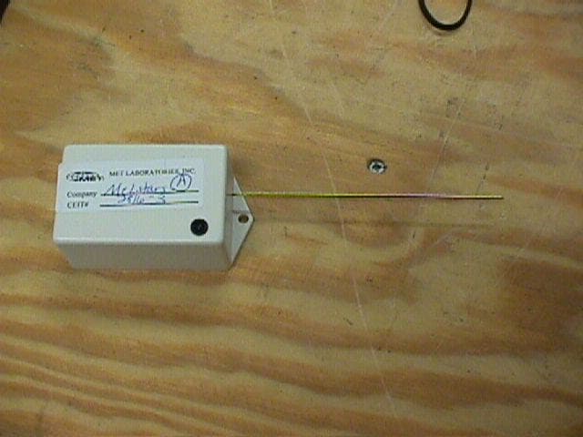
Click to zoom
Application Details
- Equipment Class
- DSC - Part 15 Security/Remote Control Transmitter
- Date of Grant
- Aug 08, 2000
- Application Purpose
- Original Equipment
- Date of Application
- Aug 08, 2000
- Equipment Note
- Wireless Light Activated Monitoring System
- Frequency Range
- 418.00000000 - 418.00000000
- Company
- Melstars, LLC
- Country
- United States
Documents & Files
Document Text
Text extracted from the exhibit documents filed with the FCC. Open a document above to read the original.
Users Manual
INSTRUCTION MANUAL WIRELESS LIGHT ACTIVATED MONITORING SYSTEM This system includes one light activated transmitter module and one or more receiver modules. SETUP: TRANSMITTER MODULE: Insert the wall transformer into a 120VAC outlet and the cord into the jack in the transmitter module. Position the transmitter module so that the light sensor on the face of the module will pick up the light (must be incandescent light) that is to be monitored. This module is not sensitive to fluorescent light. It will tolerate some ambient light without being activated. If ambient light that occurs turns the module on, reposition the module or adjust the ambient light source. Place the transmitter module, for example, in a bathroom to activate receiver modules in other rooms when the bathroom light is turned on, and to deactivate them when the light is turned off. RECEIVER MODULE: Insert the wall transformer into a 120VAC outlet and the cord into the jack in the receiver module. The receiver module may be set in any convenient location where the red LED light on its face, when activated, can be seen. Place the receiver modules, for example, in bedrooms or other rooms where individuals who would want to know whether the bathroom is occupied may be situated. (It being presumed that if the light is on, the bathroom is occupied. Users need to be instructed to always turn off the light when the bathroom is not in use) OTHER: CODING: All transmitter modules and receiver modules are coded and are marked as to their code. They must be of the same code, for example, A, B, C, D etc. to operate. Coding enables the transmitters modules and their matching receiver modules to be used in close proximity to differently coded transmitter and receiver modules without interference with each other. Additional receiver modules, if purchased to add to the system, must be of the same code. Any number of receiver modules with the same code may be added and will function off a single transmitter module. CHECKING FOR PROPER FUNCTION OF THE TRANSMITTER MODULE: The transmitter module can be easily tested to determine if it is properly placed to activate its signal when the light near it is turned on. With the transmitter module installed, place the receiver module in any location where it can be seen (it can be in the same room). Turn the light that activates the transmitter module on/off while watching to see that the red LED on the face of the receiver module responds by turning on and off. ADJUSTMENTS: There are no adjustment features or switches. The modules should not be opened or disassembled. If not functioning, return the modules to Melstars, LLC. We reserve the right to repair or replace the modules or return the purchase price. Melstars will not be responsible for repair, replacement or refund if the modules show obvious signs of misuse or abuse. Modules are guaranteed for one year from date of purchase. WARNING: The transmitter and receiver modules are each powered by a 120VAC/5.0VDC regulated wall transformer. In no event must the DC voltage exceed 5.0VDC or it will damage the transmitter or the receiver modules. FCC COMPLIANCE: This device complies with part 15 of the FCC Rules. Operation is subject to the following two conditions: (1) This device may not cause harmful interference, and (2) this device must accept any interference received, including interference that may cause undesired operation. Modifications not expressly approved by the manufacturer may void the user’s authority to operate this device. MELSTARS, LLC 8725 Falkstone Lane Alexandria, VA 22309 MET is required to submit to the FCC all documentation submitted to MET for review. Because of this all information may ONLY be supplied in the following formats: (All other formats will be rejected by the FCC) ASCII text Adobe Acrobat PDF JPEG Image Lotus 123 MS Excel MS Word Word Perfect H:\Emi\FCC LIS T.WPD Testing Lab Acceptance Criteria required by MET Laboratories, Inc. The criteria for accepting the work of another lab is as follows: 1) If accredited by Guide 25 for the EXACT testing being done than we will not require any other proof of competency and will review the Lab’s submitted test data. If any concerns rise from the review of data they will be addressed at that time. 2)If the Lab has Guide 25 accreditation in EMC type testing, but not the exact tests for which the lab is submitting data, then the Engineer who will/has perform(ed) the testing will undergo an interview by a MET Engineer with specific interest in verifying an indepth understanding of the Section of the CFR to which the Engineer(s) will be testing 3)If the Lab has Guide 25 accreditation, but not in any EMC type testing, then MET will perform an interview with the Engineer(s) who will/has perform(ed) the testing with specific interest in verifying the use of proper test equipment and techniques as well as an indepth understanding of the Section of the CFR to which the Engineer(s) will be testing. 4)If the Lab has no Guide 25 accreditation, MET laboratories will perform an investigation, using Guide 25 as a checklist, to verify the lab is capable of performing the testing for which they intend to submit data. This investigation will include a study of the Lab’s calibration, administration, quality control, technical knowledge and technical ability. As a separate criteria for acceptance, the lab in question must supply its’ site acceptance number issued by the FCC if the lab will be providing Radiated Emissions data. Data will be present to MET in a test report in the following format: 1) The following information must preference all testing sent to MET for consideration: a)Section of CFR to which the application for certification is being made b) Name and address of the Laboratory performing the testing (FCC Site # if appropriate) c) Name of the Engineer performing/responsible for testing d) Manufacturer and Model of Equipment e) Test Co nfi guratio n Used f) Justification for type of tes…
Text truncated - open the document above for the full version.
Block Diagram
Below is a functional block diagram of model # 03H-418-220K-M1 transmitter. DC Trig,Encoder Transmit pulse Once Pulse <100mS 417.88MHz per on/offOnce per cycle <100mS Encoder is an Transmitter is an integrated circuit hybrid module All clock signals are integrated within commercial purchased integrated circuits and hybrid modules. Light Sensor Encoder, W/ interna l c lo ck Tra nsmitter Module, W/ interna l c lo ck Antenna
ID Label/Location Info
*FCC Label(s) Artwork Because of the small size of the modules, the label will show only the model number. This shows the Grantee Code and the Equipment Product Code. The statement required by the FCC concerning the compliance with the FCC Part 15 Rules, is included in the instruction manual. Copy of the instruction manual is included below. *FCC Label(s) Location Diagram Back of Module TRANSMITTER FCC ID: O3H-418-220K-M1 MELSTARS, LLC TRANSMITTER FCC ID: O3H-418-220K-M1 MELSTARS, LLC
Operational Description
Description of Product as Marketed: This product provides a convenient and simple means of creating an awareness of the light situation, and presumably the occupancy, in a room such a bathroom, from other locations in the same building. It includes two modules: 1) a light activated transmitter module for a key location to be monitored and 2) a light emitting receiver module for other locations. The transmitter module is activated only by incandescent light, not fluorescent. The transmitter module can tolerate a low level of ambient light without being activated. The modules are powered by wall transformers. This system is particularly useful in homes and guesthouses where bathroom facilit ies are shared. There are many other situations where it is a lso very useful. Equipment will be operated under FCC Rule Part(s): FCC Rule Part 15.231
Test Report
FCC ID: O3H-418-220K-M1 June 28, 2000 Federal Communications Commission Authorization and Evaluation Division 7435 Oakland Mills Road Columbia, MD 21046 Attention:Applications Examiner Applicant:Melstars, LLC 8725 Falkstone Lane Alexandria, VA 22309 Equipment Classification:Low Power Transmitters Operating Periodically in the band 40.66 - 40.77 MHz and above 70 MHz FCC ID: O3H-418-220K-M1 Specification:47 CFR 15 Subpart C Unlicenced Certification Dear Examiner: The following application in support of the Grant of Equipment Authorization is presented on behalf of Melstars LLC for the Unlicenced Certification of their Model: 418-220K-M1. Enclosed, please find a complete data and documentation package demonstrating that this device complies with the technical requirements of 47 CFR 15 Subpart C. If you have any questions, please contact the undersigned, who is authorized to act as Agent. Sincerely, Chris Harvey Director, EMC Laboratory FCC ID: O3H-418-220K-M1 EMI1345- 2 -June 28, 2000 MET Laboratories, Inc. Safety Certification - EMI - Telecom Environmental Simulation 914 WEST PATAPSCO AVENUE !! BALTIMORE, MARYLAND 21230-3432 !! PHONE (410) 354-3300 !! FAX (410) 354-3313 ENGINEERING TEST REPORT in support of the Application for Grant of Equipment Authorization Equipment Classification:Low Power Transmitters Operating Periodically in the band 40.66 - 40.77 MHz and above 70 MHz FCC ID::O3H-418-220K-M1 Specification:47 CFR 15 Subpart C On Behalf of the Applicant:Melstars, LLC 8725 Falkstone Lane Alexandria, VA 22309 Manufacturer:Melstars, LLC 8725 Falkstone Lane Alexandria, VA 22309 Manufacturer’s Representative:Mr. Melvin Yuhas Test Date(s):May 31, 2000 ENGINEERING STATEMENT I ATTEST: the measurements shown in this report were made in accordance with the procedures indicated, and that the emissions from this equipment were found to be within the limits applicable. I assume full responsibility for the accuracy and completeness of these measurements. On the basis of the measurements made, the equipment tested is capable of operation in accordance with the requirements of Part 24 of the FCC Rules under normal use and maintenance. _____________________________ Liming Xu Project Engineer, MET Laboratories FCC ID: O3H-418-220K-M1 EMI1345- 3 -June 28, 2000 1.0INTRODUCTION The following data is presented on behalf of the Applicant, Melstars LLC, as verification of the compliance of the Wireless Light Activated Monitoring System to the requirements of 47CFR 15 2.0TEST SITE All testing was conducted at MET Laboratories, Inc., 914 West Patapsco Avenue, Baltimore, Maryland 21230- 3493. Radiated emissions measurements were performed on a three-meter open area test site (OATS). A complete site description is on file with the FCC Laboratory Division as 31040/SIT/MET. 3.0TEST EQUIPMENT USED ManufacturerEquipment Calibration DueCal. Interval Hewlett Packard8563A Spectrum Analyzer5/26/01annual EMCOBiconical Antenna 310409/28/00annual EMCOEMCO Log Periodic Antenna04/04/01annual EMCODouble Ridge Guided Horn2/27/01annual Hewlett Packard8594EM Analyzer11/20/00annual Rhode & Swartz (X3)SMIQ 03 Digital Signal Gen.7/30/00N/A SolarLISN7/27/00annual 4.0EQUIPMENT UNDER TEST CONFIGURATION This product consists of two small units: (l) a light triggered transmitter unit for a room to be monitored, which sends an On or Off signal a minimum of 100 feet and (2) a receiver unit for a different room (or rooms) which in response to the signal from the transmitter instantly turns On or Off a LED in the face of the receiver unit. The optical sensor on the face of the transmitter is not sensitive to fluorescent light, only to incandescent light. The transmitter and the receiver are each powered by a wall transformer 120VAC/5.0VDC. The wall transformers are existing products of another company. 5.0TEST TYPE(S) Report Section Rule Part DescriptiveCompliance Status 6.1 47CFR15.231(a)Transmission RequirementsComplies 6.2 47CFR2.1053, 15.231(b) Radiated EmissionsComplies 6.347CFR2.1049, 15.231(c) Occupied Bandwidth Complies 6.447CFR 15.107AC Line Conducted EmissionsComplies FCC ID: O3H-418-220K-M1 EMI1345- 4 -June 28, 2000 6.0TEST RESULTS 6.1TEST TYPE: Transmission Requirements 6.1.1TECHNICAL SPECIFICATION:47 CFR 15.231(a) 6.1.2TEST DATE(S):31 May 2000 6.1.3MEASUREMENT PROCEDURES: The EUT was evaluated against the requirements of 47 CFR 15.231. The requirements and the justifications for determining compliance are outlined in the table below. Rule PartRequirementJustification 15.231(a)The device must operate within 40.66-40.70 MHz or above 70 MHz The device operates at 417.88 MHz 15.231(a)The device is restricted to the transmission of control signals, no voice or data transmissions The device transmitted an uncoded single pulse transmission 15.231(a)(1)The device must meet the requirements for manual transmissions devices The device is not a manual transmissions device 15.231(a)(2)The transmission of automatically activated devices must cease within 5 seconds The device’s single transmission pulse lasts less than 100 milliseconds 15.231(a)(3)The device may not be any more periodic than one second per four hours, and only if a security function is being fulfilled The device does not transmit with any periodicity. The device is not a security device 15.231(a)(4)Emergency Service transmitters may transmit while the alarming condition exists The device is not an emergency device FCC ID: O3H-418-220K-M1 EMI1345- 5 -June 28, 2000 6.2TEST TYPE: Radiated Emissions 6.2.1TECHNICAL SPECIFICATION:15.231(b) 6.2.2TEST DATE(S):31 May 2000 6.2.3MEASUREMENT PROCEDURES: As required by 47 CFR 2.1053, radiation emissons measurements were made in accordance with the general procedures of ANSI C63.4-1992 "Methods of Measurement of Radio-Noise Emissions from Low-Voltage Electrical and Electronic Equipment in the Range of 9kHz to 40 GHz". Preliminary radiated emission measurements were performed inside a shielded chamber with all digital signal generators on …
Text truncated - open the document above for the full version.
Contact Information
Applicant
Melvin L Yuhas(President)
[email protected]406-888-5507
Test Firm
MET Laboratories, Inc.John Mason
Technical Specifications
| # | Rule Parts | Frequency Range | Power Output |
|---|---|---|---|
| 1 | 15.231 | 418 MHz - 418 MHz | - |