O3OBT600Bluetooth Car Kit
Topcell Technology Co. Ltd.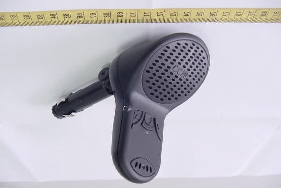
Click to zoom
Application Details
- Equipment Class
- DSS - Part 15 Spread Spectrum Transmitter
- Date of Grant
- Mar 30, 2004
- Application Purpose
- Original Equipment
- Date of Application
- Mar 30, 2004
- Equipment Note
- Bluetooth Car Kit
- Frequency Range
- 2402.00000000 - 2480.00000000
- Company
- Topcell Technology Co. Ltd.
- Country
- Taiwan
Documents & Files
Document Text
Text extracted from the exhibit documents filed with the FCC. Open a document above to read the original.
External Photos
ETC Report No. : ET93R-02-078-04 FCC ID. : O3OBT600 Rev. No 2.1 CONSTRUCTED PHOTOS of EUT Front View of EUT Side View of EUT ETC Report No. : ET93R-02-078-04 FCC ID. : O3OBT600 Rev. No 2.1 CONSTRUCTED PHOTOS of EUT Side View of EUT Side View of EUT ETC Report No. : ET93R-02-078-04 FCC ID. : O3OBT600 Rev. No 2.1 CONSTRUCTED PHOTOS of EUT Side View of EUT Rear View of EUT
Internal Photos
ETC Report No. : ET93R-02-078-04 FCC ID. : O3OBT600 Rev. No 2.1 CONSTRUCTED PHOTOS of EUT Internal View of EUT ETC Report No. : ET93R-02-078-04 FCC ID. : O3OBT600 Rev. No 2.1 CONSTRUCTED PHOTOS of EUT Component View of Main PCB Solder View of Main PCB ETC Report No. : ET93R-02-078-04 FCC ID. : O3OBT600 Rev. No 2.1 CONSTRUCTED PHOTOS of EUT Component View of PCB Solder View of PCB
Operational Description
Bluetooth Declaration Per FCC 15.247 Requirements 1 Output power and channel separation of a Bluetooth device in the different operating modes: The different operating modes (data-mode, acquisition-mode) of a Bluetooth device don’t influence the output power and the channel spacing. There is only one transmitter which is driven by identical input parameters concerning these two parameters. Only a different hopping sequence will be used. For this reason the check of these RF parameters in one op-mode is sufficient. 2 Frequency range of a Bluetooth device: Hereby we declare that the maximum frequency of this device is: 2402 – 2480 MHz. This is according the Bluetooth Core Specification V 1.0B (+ critical errata) for devices which will be operated in the USA. This was checked during the Bluetooth Qualification tests (Test Case: TRM/CA/04-E). Other frequency ranges ( e.g. for Spain, France, Japan) which are allowed according the Core Specification are not supported by this device. 3 Co-ordination of the hopping sequence in data mode to avoid simultaneous occupancy by multiple transmitters: Bluetooth units which want to communicate with other units must be organized in a structure called piconet. This piconet consist of max. 8 Bluetooth units. One unit is the master the other seven are the slaves. The master co-ordinates frequency occupation in this piconet for all units. As the master hop sequence is derived from it’s BD address which is unique for every Bluetooth device, additional masters intending to establish new piconets will always use different hop sequences. 4 Example of a hopping sequence in data mode: Example of a 79 hopping sequence in data mode: 40, 21, 44, 23, 42, 53, 46, 55, 48, 33, 52, 35, 50, 65, 54, 67, 56, 37, 60, 39, 58, 69, 62, 71, 64, 25, 68, 27, 66, 57, 70, 59, 72, 29, 76, 31, 74, 61, 78, 63, 01, 41, 05, 43, 03, 73, 07, 75, 09, 45, 13, 47, 11, 77, 15, 00, 64, 49, 66, 53, 68, 02, 70, 06, 01, 51, 03, 55, 05, 04 5 Equally average use of frequencies in data mode and behaviour for short transmissions: The generation of the hopping sequence in connection mode depends essentially on two input values: 1. LAP/UAP of the master of the connection 2. Internal master clock The LAP (lower address part) are the 24 LSB’s of the 48 BD_ADDRESS. The BD_ADDRESS is an unambiguous number of every Bluetooth unit. The UAP (upper address part) are the 24 MSB’s of the 48 BD_ADDRESS. The internal clock of a Bluetooth unit is derived from a free running clock which is never adjusted and is never turned off. For synchronisation with other units only offset are used. It has no relation to the time of the day. Its resolution is at least half the RX/TX slot length of 312.5 μs. The clock has a cycle of about one day (23h30). In most case it is implemented as 28 bit counter. For the deriving of the hopping sequence the entire LAP (24 bits), 4 LSB’s (4 bits) (Input 1) and the 27 MSB’s of the clock (Input 2) are used. With this input values different mathematical procedures (permutations, additions, XOR-operations) are performed to generate the sequence. This will be done at the beginning of every new transmission. Regarding short transmissions the Bluetooth system has the following behaviors: The first connection between the two devices is established, a hopping sequence was generated. For transmitting the wanted data the complete hopping sequence was not used. The connection ended. The second connection will be established. A new hopping sequence is generated. Due to the fact that the Bluetooth clock has a different value, because the period between the two transmission is longer (and it cannot be shorter) than the minimum resolution of the clock (312.5 μs). The hopping sequence will always differ from the first one. 6 Receiver input bandwidth and behaviors for repeated single or multiple packets: The input bandwidth of the receiver is 1 MHz. In every connection one Bluetooth device is the master and the other one is the slave. The master determines the hopping sequence (see chapter 5). The slave follows this sequence. Both devices shift between RX and TX time slot according to the clock of the master. Additionally the type of connection (e.g. single or multislot packet) is set up at the beginning of the connection. The master adapts its hopping frequency and its TX/RX timing according to the packet type of the connection. Also the slave of the connection will use these settings. Repeating of a packet has no influence on the hopping sequence. The hopping sequence generated by the master of the connection will be followed in any case. That means, a repeated packet will not be send on the same frequency, it is send on the next frequency of the hopping sequence. 7 Dwell time in data mode The dwell time of 0.3797s within a 30 second period in data mode is independent from the packet type (packet length). The calculation for a 30 second period is a follows: Dwell time = time slot length * hop rate / number of hopping channels *30s Example for a DH1 packet (with a maximum length of one time slot) Dwell time = 625 μs * 1600 1/s / 79 * 30s = 0.3797s (in a 30s period) For multislot packet the hopping is reduced according to the length of the packet. Example for a DH5 packet (with a maximum length of five time slots) Dwell time = 5 * 625 μs * 1600 * 1/5 *1/s / 79 * 30s = 0.3797s (in a 30s period) This is according the Bluetooth Core Specification V 1.0B (+ critical errata) for all Bluetooth devices. There for all Bluetooth devices comply with the FCC dwell time requirement in data mode. This was checked during the Bluetooth Qualification tests. The Dwell time in hybrid mode is measured and stated in the test report. 8 Channel Separation in hybrid mode The nominal channel spacing of the Bluetooth system is 1Mhz independent of the operating mode. The maximum “initial carrier frequency tolerance” which is allowed for Bluetooth is fcenter = 75 kHz. This was checked during the Bluetooth Qualification tests (Test Case:…
Text truncated - open the document above for the full version.
Test Report
Rev. No 2.1 FCC Part 15 EMI TEST REPORT of E.U.T. Bluetooth Car Kit Model 50236 FCC ID. O3OBT600 for APPLICANT TOPCELL TECHNOLOGY CO., LTD. ADDRESS NO. 403, JUNG MIN ROAD, CHUNGLI, TAOYUAN HSIEN, TAIWAN, R.O.C Test Performed by ELECTRONICS TESTING CENTER, TAIWAN NO. 34, LIN 5, DING FU TSUN, LINKOU HSIANG, TAIPEI HSIEN, TAIWAN, R.O.C. Tel:(02)26023052 Fax:(02)26010910 http://www.etc.org.tw ; e-mail:[email protected] Report Number : ET93R-02-078-04 ETC Report No. : ET93R-02-078-04 FCC ID. : O3OBT600 Rev. No 2.1 TEST REPORT CERTIFICATION Applicant : TOPCELL TECHNOLOGY CO., LTD. : NO. 403, JUNG MIN ROAD, CHUNGLI, TAOYUAN HSIEN, TAIWAN, R.O.C. Applicant : TOPCELL TECHNOLOGY CO., LTD. : NO. 403, JUNG MIN ROAD, CHUNGLI, TAOYUAN HSIEN, TAIWAN, R.O.C. Description of EUT : a) Type of EUT : Bluetooth Car Kit b) Trade Name : CCM c) Model No. : 50236 d) Power Supply : 12Vdc Regulation Applied : FCC Rules and Regulations Part 15 Subpart B & C (2003) I HEREBY CERTIFY THAT: The data shown in this report were made in accordance with the procedures given in ANSI C63.4, and the energy emitted by the device was founded to be within the limits applicable. I assume full responsibility for accuracy and completeness of these data. Note: 1. The result of the testing report relates only to the item tested. 2. The testing report shall not be reproduced expect in full, without the written approval of ETC. Issued Date : Mar. 24, 2004 Test Engineer : ( Jiapeng Chen ) Approve & Authorized Signer : Will Yauo, Manager EMC Dept. II of ELECTRONICS TESTING CENTER, TAIWAN ETC Report No. : ET93R-02-078-04 FCC ID. : O3OBT600 Rev. No 2.1 Table of Contents Page 1 GENERAL INFORMATION........................................................................................................1 1.1 Product Description........................................................................................................................1 1.2 Characteristics of Device.................................................................................................................1 1.3 Test Methodology...........................................................................................................................1 1.4 Test Facility....................................................................................................................................1 2 PROVISIONS APPLICABLE........................................................................................................2 2.1 Definition........................................................................................................................................2 2.2 Requirement for Compliance...........................................................................................................3 2.3 Restricted Bands of Operation.........................................................................................................5 2.5 User Information.............................................................................................................................6 3. SYSTEM TEST CONFIGURATION............................................................................................7 3.1 Justification.....................................................................................................................................7 3.2 Devices for Tested System..............................................................................................................7 4 RADIATED EMISSION MEASUREMENT...............................................................................8 4.1 Applicable Standard........................................................................................................................8 4.2 Measurement Procedure.................................................................................................................8 4.3 Measuring Instrument....................................................................................................................10 4.4 Radiated Emission Data.................................................................................................................11 4.4.1 Fundatmental and Harmonics...................................................................................................11 4.4.2 Radiated Emissions in Restricted Bands....................................................................................14 4.4.3 Other Emissions......................................................................................................................15 4.5 Field Strength Calculation..............................................................................................................15 4.6 Photos of Radiation Measuring Setup............................................................................................16 5 CONDUCTED EMISSION MEASUREMENT.........................................................................17 5.1 Description...................................................................................................................................17 6 ANTENNA REQUIREMENT.....................................................................................................18 6.1 Standard Applicable......................................................................................................................18 6.2 Antenna Connected Construction..................................................................................................18 7 HOPPING CHANNEL SEPARATION.......................................................................................19 7.1 Standard Applicable......................................................................................................................19 7.2 Measurement Procedure...............................................................................................................19 7.3 Measurement Equipment...............................................................…
Text truncated - open the document above for the full version.
Test Report
ETC Report No. : ET93R-02-078-04 Sheet 18 of 35 Sheets FCC ID. : O3OBT600 Rev. No 2.1 Appendix 5 : Plotted Data for Output Peak Power ETC Report No. : ET93R-02-078-04 Sheet 19 of 35 Sheets FCC ID. : O3OBT600 Rev. No 2.1 ETC Report No. : ET93R-02-078-04 Sheet 20 of 35 Sheets FCC ID. : O3OBT600 Rev. No 2.1 ETC Report No. : ET93R-02-078-04 Sheet 21 of 35 Sheets FCC ID. : O3OBT600 Rev. No 2.1 ETC Report No. : ET93R-02-078-04 Sheet 22 of 35 Sheets FCC ID. : O3OBT600 Rev. No 2.1 Appendix 6 : Plotted Data for 100 kHz Bandwidth from Band Edge ETC Report No. : ET93R-02-078-04 Sheet 23 of 35 Sheets FCC ID. : O3OBT600 Rev. No 2.1 ETC Report No. : ET93R-02-078-04 Sheet 24 of 35 Sheets FCC ID. : O3OBT600 Rev. No 2.1 ETC Report No. : ET93R-02-078-04 Sheet 25 of 35 Sheets FCC ID. : O3OBT600 Rev. No 2.1 Appendix 7 : Plotted Data for Out-of-Band Conducted Emission ETC Report No. : ET93R-02-078-04 Sheet 26 of 35 Sheets FCC ID. : O3OBT600 Rev. No 2.1 ETC Report No. : ET93R-02-078-04 Sheet 27 of 35 Sheets FCC ID. : O3OBT600 Rev. No 2.1 ETC Report No. : ET93R-02-078-04 Sheet 28 of 35 Sheets FCC ID. : O3OBT600 Rev. No 2.1 ETC Report No. : ET93R-02-078-04 Sheet 29 of 35 Sheets FCC ID. : O3OBT600 Rev. No 2.1 ETC Report No. : ET93R-02-078-04 Sheet 30 of 35 Sheets FCC ID. : O3OBT600 Rev. No 2.1 ETC Report No. : ET93R-02-078-04 Sheet 31 of 35 Sheets FCC ID. : O3OBT600 Rev. No 2.1 ETC Report No. : ET93R-02-078-04 Sheet 32 of 35 Sheets FCC ID. : O3OBT600 Rev. No 2.1 Appendix 8 : Plotted Data for Peak Power Spectral Density ETC Report No. : ET93R-02-078-04 Sheet 33 of 35 Sheets FCC ID. : O3OBT600 Rev. No 2.1 ETC Report No. : ET93R-02-078-04 Sheet 34 of 35 Sheets FCC ID. : O3OBT600 Rev. No 2.1 ETC Report No. : ET93R-02-078-04 Sheet 35 of 35 Sheets FCC ID. : O3OBT600 Rev. No 2.1
Test Setup Photos
FCC ID. : O3OBT600 Rev. No 2.1 Photos of Radiation Measuring Setup
Contact Information
Applicant
Robert Lung(President)
Test Firm
Electronics Testing Center, TaiwanWin-Po Tsai
Technical Specifications
| # | Rule Parts | Frequency Range | Power Output |
|---|---|---|---|
| 1 | 15C | 2.40 GHz - 2.48 GHz | 900.00 µW |
Other Applications from Topcell Technology Co. Ltd.
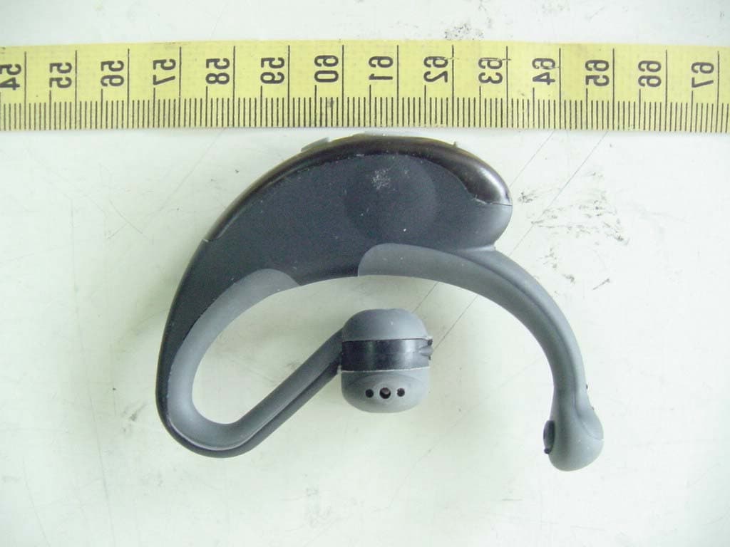
O3OCCM03
Nov 25, 2003Bluetooth Headset
Equipment Class
DSS - Part 15 Spread Spectrum Transmitter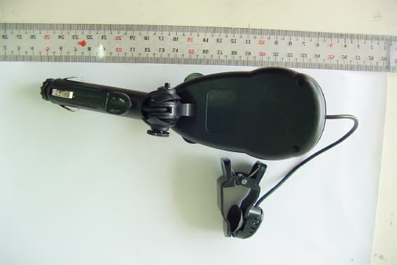
O3OTOPUHF01
Apr 24, 2002Universal Hand Free
Equipment Class
DXX - Part 15 Low Power Communication Device Transmitter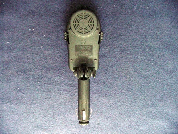
O3OCCMWH01
Sep 18, 2000Wireless Plug-In Holder Hands Free
Equipment Class
DXX - Part 15 Low Power Communication Device Transmitter