O4TTX3312NRemote Control Duck Decoy
The Purchasing Department, Inc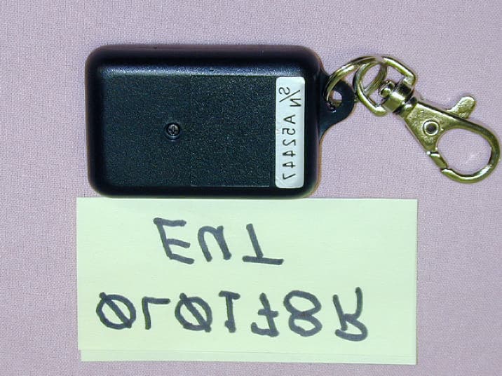
Click to zoom
Application Details
- Equipment Class
- DSC - Part 15 Security/Remote Control Transmitter
- Date of Grant
- Aug 01, 2000
- Application Purpose
- Original Equipment
- Date of Application
- Aug 01, 2000
- Equipment Note
- Remote Control Duck Decoy
- Frequency Range
- 433.00000000 - 434.00000000
- Country
- United States
Documents & Files
Document Text
Text extracted from the exhibit documents filed with the FCC. Open a document above to read the original.
Block Diagram
BLOCK DIAGRAM PT2262 Encoder loop antenna Oscillator/PA GND +12V 434 MHz
ID Label/Location Info
FCC ID: O4TTX3312N S/N A52447 FCC ID: O4TTX3312N 1.00 0.38 Label dimensions (inches) Label placement
ID Label/Location Info
1" FCC ID:O4TTX3312N 0.38 FCC ID:O4TTX3312N
Operational Description
Circuit Description Application: The TX-3312N transmitter is a periodic type transmitter used to remotely control a duck decoy. There are two function buttons; one button activates functions set in the decoy receiver and the second button stops the functions. Circuit: The circuit is a simple encoder IC that creates a unique identification code and modulates a simple Colpitts oscillator circuit. The antenna is a loop etched on the PWB. Antenna tuning is accomplished with a trim capacitor in the transmit loop. Receiver: The companion receiver is a simple super-regenerative design. Several control functions are set in the decoy circuit whereby a motor control circuit accomplishes movements of the decoy. The decoy has been approved under a Declaration of Conformity per Part 15, Subpart B.
Test Report
KTL Test Report:0L0178RUS1 Applicant:The Purchasing Department, Inc. 160 E. Poplar, Suite C Fayetteville, AR 72703 Equipment Under Test:TX-3312N (E.U.T.) FCC ID:O4TTX3312N In Accordance With:FCC Part 15, Subpart C For Low Power Transmitters Operating Periodically In The Band 40.66 - 40.77 MHz And Above 70 MHz Tested By:KTL Dallas, Inc. 802 N. Kealy Lewisville, TX 75057-3136 Authorized By: Tom Tidwell, Wireless Group Manager Date:7/26/00 Total Number of Pages:25 KTL Dallas, Inc. FCC PART 15, SUBPART C FOR LOW POWER TRANSMITTERS EQUIPMENT: TX-3312N FCC ID.: O4TTX3312N PROJECT NO.: 0L0178RUS Page 2 of 25 TABLE OF CONTENTS Section 1. Summary of Test Results........................................................................................3 Section 2. Equipment Under Test (E.U.T.)..............................................................................5 Section 3. Equipment Configuration........................................................................................8 Section 4. Transmission Requirements.....................................................................................9 Section 5. Radiated Emissions...............................................................................................15 Section 6. Occupied Bandwidth.............................................................................................18 Section 7. Frequency Tolerance Devices in the Frequency Band 40.66 - 40.77 MHz..........19 Section 8. Periodic Alternate Field Strength Requirements.....................................................20 Section 9. Powerline Conducted Emissions............................................................................21 Section 10.Block Diagrams.....................................................................................................22 Section 11. Test Equipment List..............................................................................................24 ANNEX A - RESTRICTED BANDS.......................................................................................25 KTL Dallas, Inc. FCC PART 15, SUBPART C FOR LOW POWER TRANSMITTERS EQUIPMENT: TX-3312N FCC ID.: O4TTX3312N PROJECT NO.: 0L0178RUS Page 3 of 25 Section 1.Summary of Test Results Model No.:TX-3312N Serial No.:A52447 General:All measurements are traceable to national standards. These tests were conducted on a sample of the equipment for the purpose of demonstrating compliance with Part 15, Subpart C, Paragraph 15.231. All tests were conducted using measurement procedure ANSI C63.4-1992. Radiated emissions are made on an open area test site. A description of the test facility is on file with the FCC. New SubmissionProduction Unit Class II Permissive ChangePre-Production Unit THIS TEST REPORT RELATES ONLY TO THE ITEM(S) TESTED. THE FOLLOWING DEVIATIONS FROM, ADDITIONS TO, OR EXCLUSIONS FROM THE TEST SPECIFICATIONS HAVE BEEN MADE. See “ Summary of Test Data”. NVLAP LAB CODE: 100426-0 KTL Dallas Inc. authorizes the above named company to reproduce this report provided it is reproduced in its entirety and for use by the company’s employees only. Any use which a third party makes of this report, or any reliance on or decisions to be made based on it, are the responsibility of such third parties. KTL Dallas Inc. accepts no responsibility for damages, if any, suffered by any third party as a result of decisions made or actions based on this report. This report applies only to the items tested. KTL Dallas, Inc. FCC PART 15, SUBPART C FOR LOW POWER TRANSMITTERS EQUIPMENT: TX-3312N FCC ID.: O4TTX3312N PROJECT NO.: 0L0178RUS Page 4 of 25 Summary Of Test Data Name of TestParagraph No.Results Transmission Requirements15.231(a)Complies Radiated Emissions15.231(b)Complies Occupied Bandwidth15.231(c)Complies Frequency Tolerance (1) 15.231(d)N/A Periodic Alternate Field Strength Requirements (2) 15.231(e)N/A Powerline Conducted Emissions (3) 15.207N/A Footnotes For N/A’s:(1)The unit does not operate in the designated band for this requirement. (2)The device meets the requirements of 15,231(a). (3)The device is DC (battery) powered KTL Dallas, Inc. FCC PART 15, SUBPART C FOR LOW POWER TRANSMITTERS EQUIPMENT: TX-3312N FCC ID.: O4TTX3312N PROJECT NO.: 0L0178RUS Page 5 of 25 Section 2.Equipment Under Test (E.U.T.) General Equipment Information Frequency Range: 434 - 434 (Fixed) Operating Frequency(ies) of Sample: 434 MHz Type of Emission: Pulse Code Modulation Emission Designator: 48K5L1D Supply Power Requirement: 12 Volt Alkaline battery Duty Cycle Correction Factor: -3.2 dB KTL Dallas, Inc. FCC PART 15, SUBPART C FOR LOW POWER TRANSMITTERS EQUIPMENT: TX-3312N FCC ID.: O4TTX3312N PROJECT NO.: 0L0178RUS Page 6 of 25 Description of E.U.T. Key fob type RF transmitter used for remote actuation. Modifications Incorporated in E.U.T. The EUT has not been modified from what is described by the brand name and unique type identification stated above. KTL Dallas, Inc. FCC PART 15, SUBPART C FOR LOW POWER TRANSMITTERS EQUIPMENT: TX-3312N FCC ID.: O4TTX3312N PROJECT NO.: 0L0178RUS Page 7 of 25 Justification The E.U.T. was configured for testing as per typical installation. The following combinations were investigated to establish worst case configuration: (1) Lying flat. (Worst case) (2) Upright, Horizontal (3) Upright, Vertical Exercise Program The E.U.T. exercise program used during radiated and conducted testing was designed to exercise the various system components in a manner similar to typical use. Exercise mode: (1) Continuous transmit KTL Dallas, Inc. FCC PART 15, SUBPART C FOR LOW POWER TRANSMITTERS EQUIPMENT: TX-3312N FCC ID.: O4TTX3312N PROJECT NO.: 0L0178RUS Page 8 of 25 Section 3.Equipment Configuration Equipment Configuration List: ItemDescriptionModel No.Serial.Rev. (A)TransmitterTX-3312NA52447 Inter-connection Cables: There are no interconnecting cables. The unit is self-contained. Configuration of the Equipment Under Test (E.U.T) KTL Dallas, Inc. FCC PART 15, SUBPART C FOR LOW POWE…
Text truncated - open the document above for the full version.
Test Report
Dear Mr. Curtis, I have checked into the matters you raise and have answered below. Thank you for your kind comments. Regards, Tom > -----Original Message----- > From: Certification Manager [SMTP:[email protected]] > Sent: Friday, July 28, 2000 1:13 PM > To: Tom Tidwell > Subject: FCC Application TX3312N > > Dear Mr. Tidwell, > > Thank you very much for your business. Your application was truly well > organized and a pleasure to review. > > I have the following issues to resolved before I can grant your > application. > > 1. The test report says that antenna 2017 was used and the equipment > sheet shows that antenna as calibrated on 01/25/99. Since the test was > performed on 6/6/00, that antenna is beyond an annual calibration. > Please explain how this complies with ANSI C63.4 clause 4.4.1. It is > possible to go more than 1 year between "official" calibrations if you > have some other means of checking that your antenna factors are ok in > the interim. Let me know what it is that you do. [Tom Tidwell] Apparently the automated test equipment list generation picked up a calibration date from a list that was not updated. Probably it did not update the file link. The last calibration on that antenna was 2/26/00. Our records show that the antenna was checked on 1/26/99 and a calibration extension was issued for one week based on the calibration check. The antenna was then calibrated 2/26/00. > 2. Similarly, your equipment sheet does not appear to contain any > cables longer than 2m and does not contain cable C1A noted in the data > sheet. Is this cable a calibrated item? How long is it? [Tom Tidwell] The cable is the feeder cable that is buried in conduit and connects from our control building to the OATS. The cable is 30 m in length. It is calibrated annually. The last calibration was 2/26/00. > 3. I am unable to verify the code O4T in the FCC database. I think > this means that when I try to fill out the 731 form on the TCB upload > site that I will not be able to proceed. Once we resolve the other > issues, I will try to upload the 731 form and get your grant. I cannot > get your grant if the FCC site blocks me because it doesn't recognize > your grantee code. I urge you to pay for your code as soon as possible > as maybe that is why it isn't in the database yet. Please also check > the code to see that you have given me the correct one. I tried both > O4T and 04T. [Tom Tidwell] I paid the fee on-line via credit card on 7/12/00 10:24 AM. I have a remittance ID number (64729) and an authorization number (012890). I will FAX you the confirmation and transaction notice forms that I printed from the FCC site. I will FAX these to you. > 4. The schematic says 433MHz. Please confirm that you want a grant for > just 434 MHz. 433MHz actually makes a lot more sense if you consider > the restricted band at 1300MHz. You comply either way. This is not > something that will hold up your grant, it's just for your information. [Tom Tidwell] Actually the transmitter is nominally 433 MHz by design. I agree that that makes more sense. Yes, 433 MHz - 434 MHz would be preferrable. > 5. For your information I called up your accounting department and they > gave me a credit card number to bill against.
Test Setup Photos
KTL Dallas, Inc. FCC PART 15, SUBPART C FOR LOW POWER TRANSMITTERS EQUIPMENT: TX-3312N FCC ID.: O4TTX3312N PROJECT NO.: 0L0178RUS Page 17 of 25 Radiated Photographs(Worst Case Configuration) FRONT VIEW REAR VIEW
Contact Information
Applicant
Tim Stout
[email protected]507-571-4225
Technical Contact
KTL Dallas, Inc.Tom Tidwell
[email protected]972-436-9600
802 N. Kealy · Lewisville, Texas · United States
Non-Technical Contact
KTL Dallas, Inc.Tom Tidwell
[email protected]972-436-9600
Test Firm
Nemko Dallas, Inc.Michael Cantwell
Technical Specifications
| # | Rule Parts | Frequency Range | Power Output |
|---|---|---|---|
| 1 | 15.231 | 433 MHz - 434 MHz | - |
Other Applications from The Purchasing Department, Inc
O4TTX3314S
Aug 09, 2000Wireless duck decoy controller
Equipment Class
DSC - Part 15 Security/Remote Control Transmitter