O4WLEGENDPager Receiver
Dynafine Inc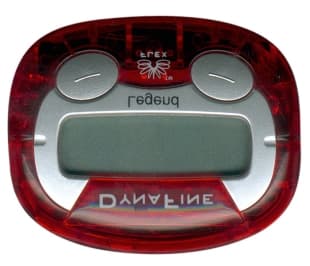
Click to zoom
Application Details
- Equipment Class
- CXX - Communications Rcvr for use w/ licensed Tx and CBs
- Date of Grant
- Mar 22, 2001
- Application Purpose
- Original Equipment
- Date of Application
- Mar 13, 2001
- Equipment Note
- Pager Receiver
- Frequency Range
- 929.01250000 - 929.01250000
- Company
- Dynafine Inc
- Country
- South Korea
Documents & Files
Document Text
Text extracted from the exhibit documents filed with the FCC. Open a document above to read the original.
Users Manual
MANUAL FOR INSTALLATION AND OPERATING INSTRUCTION Model : Legend CONTENTS 1. PAGER STANDARD FEATURES •••••••••••••• 5 2. BUTTONS ••••••••••••••••••••••• 6 3. DEFINITION AND TYPE OF ICONS •••••••••••• 7 4. INSERTING / REPLACING BATTERY ••••••••••• 8 5. SELECTION OF ALERT MODE ••••••••••••••• 9 6. OVERVIEW OF OTHER BUILT IN FUNCTIONS ••••••• 11 7. SELECTING BEEP / CHIRP / MELODY ALERT ••••••• 12 8. KEY TONE ON / OFF ••••••••••• ••••••• 13 9. ERASE ALL •••••••••••••••••••••• 14 10. SETTING THE TIME AND DATE ••••••••••••• 15 11. SETTING THE ALARM •••••••••••••••••• 16 12. SETTING AUTO ON / OFF •••••••••••••••• 18 13. TURNING ON/OFF THE PAGER •••••••••••••• 20 14. RECEVING AND READING MESSAGE ••••••••••• 21 15. READING STORED & LOCKING MESSAGES •••••••• 23 16. LOCKING AND UNLOCKING MESSAGE •••••••••• 26 17. DELETING MESSAGE •••••••••••••••••• 29 1. PAGER STANDARD FEATURES The LEGEND provides the following features as standard: 1. 1 line display (1 line x 12 digit) 2. Total memory capacity : 400 digits (20digit x 20 messages) 3. Locks up to 20 messages 4. 3 Standard alert modes : Sound, Vibrate & Silent 5. 4 Beep, 1 Chirp & 8 Melody alerts 6. Key tone On/Off 7. Real time clock (12 hours) with calendar date display 8. Alarm clock 9. Delete individual message or erase all 10. Message time stamping 11. Service area indication 12. Automatic Power On/Off 13. Low battery indication 14. Back lighting 15. Reminder Alert 2. BUTTONS The pager has 2 push buttons (Read and select buttons) for the pager controls and operations. A. Select Button Turn the back light on and enter into the function change mode. B. Read Button Read message and set the pager function mode. 3. DEFINITION AND TYPE OF LCD ICONS This device complies with Part 15 of the FCC Rules. Operation is subject to the following two conditions: (1) this device may not cause harmful interference, and (2) this device must accept any interference received, including interference that may cause undesired operation. Caution : Any change or modifications in constructions of this device which are not expressly approved by the party responsible for compliance could void the user’s authority to operate the equipment. Receivable Area Message Lock Sound Duplicate Message MelodyLow Battery Vibration Message Full Alarm Message Extension Auto On/Off 4. INSERTING / REPLACING BATTERY 1. Slide the battery locking switch to the unlock position. 2. Slide the battery cover and separate it from the pager. 3. Insert the battery paying attention to the battery polarity marked in the battery compartment. 4. Slide the battery cover back on the pager and slide the battery locking switch to the locked position. 5.SELECTION OF ALERT MODE - Alert Tone Mode, Vibration Mode, Silent Mode – You can change the alert mode in a serial order of Alert Tone Mode, Vibration Mode and Silent Mode. After inserting battery, the initial alert mode is Alert Tone Mode. <Alert Tone Mode> If you want to change Alert Tone Mode to Vibration Mode, press the SELECT button twice, then “VIbRATE ? ” will appear. If you press the SELECT button once more, the pager will return to the standby mode displayi ng the current time and the vibration icon will appear i ndicating the change. <Vibration Mode> As this, you can also change Vibration Mode to Silent Mode or Silent Mode to Alert Tone Mode in the same method. <Silent Mode> 6. OVERVIEW OF OTHER BUILT IN FUNCTIONS The LEGEND has 7 menu functions. These are “SET MELODY”, “KEY TONE ON/OFF”, “ERASE ALL”, “SET TIME”, “SET ALARM”, “SET AUTO ON/OFF”, “POWER OFF”. By pressing the SELECT button twice and the READ button once you’ll enter into the menu functions. 7. SELECTING BEEP/ CHIRP/ MELODY ALERT Press the SELECT button twice and the READ button once to the “SET MELodY ?” mode. You can choose any one of desired beep tone, chirp or melody. Press the SELECT button again the current tone will sound and its corresponding number will appear as displayed below. If you press the SELECT button once more, the next alert tone number is displayed and the corresponding alert tone will sound. Press SELECT button to select the desired alert. Pager returns to standby after that. 8. KEY TONE ON / OFF Press the SELECT button twice and the READ button twice, “KEY TonE ?” menu will appear. If you press the SELECT button, the current setting will be displayed and blinking. To change “ON/OFF” setting, press the READ button and the setting will be toggled between “On” and “Off”. After selecting “On” or “Off”, press the SELECT button to return to the standby mode. 9. ERASE ALL If you want to erase all stored unlocked messages, press the SELECT button twice and the READ button three times to the “ERASE ALL” mode. Press the SELECT button once and the “dELETEd” is displayed and all stored messages except for locked messages are erased. 10. SETTING THE TIME AND DATE Press the SELECT button twice and the READ button four times, “SET TIME ?” menu will appear. Press the SELECT button, and the month number will be blinking, press the READ button to the desired month and then press SELECT button. After that the day number will be blinking and you can set the desired day. Repeat the procedure for hour, minute, and AM/PM selections. 11. SETTING THE ALARM Press the SELECT button twice and the READ button five times, “SET ALARM ?” menu will appear. Press the SELECT button and “ALARM oFF” will be displayed. This can be toggled between “ON” and “OFF” by pressing the READ button. If yo u w a nt to use the A LAR M functio n, select “A LA RM ON” a nd press the SE LE CT b utto n, a nd yo u can set the desired ALARM time by the procedure in “SETTING TIME”. If you press the SELECT button in the state of displaying “ALARM oFF”, pager will return to the standby mode. 12. SETTING AUTO ON/OFF Press the SELECT button twice and the READ button six times, “SET Auto?” menu will appear. Press the SELECT button, “Auto oFF” will be displayed. If you want to use the AUTO ON/OFF function, select “Auto on” by pre…
Text truncated - open the document above for the full version.
External Photos
LEGEND 930 PLL FLEX TOP VIEW LEGEND 930 PLL FLEX BOTTOM VIEW
ID Label/Location Info
Legend 930 PLL FLEX LABEL
Internal Photos
LEGEND 930 PLL FLEX DIGITAL TOP VIEW LEGEND 930 PLL FLEX DIGITAL BOTTOM VIEW LEGEND 930 PLL FLEX RF TOP VIEW LEGEND 930 PLL FLEX RF BOTTOM VIEW
Test Report
KTL Korea Testing Laboratory Page 1 of 8 TEST REPORT This test report only responds to the tested sample and shall not be reproduced except in full without written approval of the Korea Testing Laboratory. Tested and reported by Reviewed by Jeong-Min Kim , Senior Engineer Won-Seo Cho , EMC Team Leader KOREA TESTING LABORATORY FG101-01-02-00 222-13, Guro-Dong Guro-Gu Seoul Korea 152-053 http://www.ktl.re.kr Ref. Report No. 01-341-014 Name and address of the applicant DYNAFINE INC. Room 905, DongAh-Height Bldg., 449-1, Sang-Dong, Wonmi-Ku, Bucheon-Shi, Kyungki-Do, Korea 420-030 Standard / Test regulation FCC Part 15, Subpart B Test result Pass Incoming date : March 8, 2001 Test item( s) ; Communicat ion Re ce ive r (Page r Re ce ive r) Model/type ref. ; LEGEND Manufacturer ; DYNAFINE INC. Additional information ; -Re quire d Aut ho riz atio n : Ce rtificatio n -FCC ID. : O4WLEGEND Test date : March 14, 2001Issue date : March 15, 2001 Ref. Report No. 01 - 341 - 014 2 Page of 8 TABLE O F CONTENTS I. GENERAL INFORMATION ............................................................................................................ 3 1. Grantee’s Name and Mailing Address 2. Manufacturer's Name and Mailing Address 3. Equipment Descriptions 4. Rules and Regulations 5. Measuring Procedure 6. Date of Measurement α. GENERAL REQUIREMENTS OF THE EUT .................................................................4 1. Labelling Requirement (Section 15.19) 2. Information to User (Sections 15.21) 3. Special Accessories (Section 15.27) β. RADIATED EMISSION MEASUREMENT (Section 15.109) ...........................................................5 1. Test Procedure 2. Photograph for the worst case configuration 3. Sample Calculation 4. Measurement Data χ. TEST EQUIPMENTS USED FOR MEASUREMENT..................................................................8 Ref. Report No. 01 - 341 - 014 3 Page of 8 . GENERAL INFORMATION 1. Grantee’s Na me and : DYNAFINE INC. Mailing Address Room 905, DongAh-Height Bldg., 449-1, Sang-Dong, Wonmi-Ku, Bucheon-Shi, Kyungki-Do, Korea 420-030 2. Manufacturer's Name and: DYNAFINE INC. Mailing AddressRoom 905, DongAh-Height Bldg., 449-1, Sang-Dong, Wonmi-Ku, Bucheon-Shi, Kyungki-Do, Korea 420-030 3. Equipment Descriptions 3.1 Operating Frequency : 929.0125 MHz 3.2 Detect Method : Superheterodyne Detector 3.3 Local Oscillator: 1st Local Osc. Frequency = Operating Frequency - 21.4 MHz (1st IF) 2nd Local Osc. Frequency = 20.945 MHz (2nd IF : 455 kHz) 3.4 Oscillator: Crystal = 12.8 MHz, 20.945 MHz, 4.19 MHz 3.5 Power Supply : DC 1.5V (Battery) 4. Rules and Regulations: FCC Part 15, Subpart B 5. Measuring Procedure: ANSI C63.4-1992 6. Date of Measurement 6.1 Line Conducted: Not Applicable 6.2 Radiated Emission : March 14, 2001 Ref. Report No. 01 - 341 - 014 4 Page of 8 . GENERAL REQUIREMENTS O F THE EUT 1. Labelling Requirement (Section 15.19) This device complies with Part 15 of the FCC Rules. Operation is subject to the following two conditions: (1) this device may not cause harmful interference, and (2) this device must accept any interference received, including interference that may cause undesired operation . 1.1 Location of Label : User’s Guide Manual 1.2 How Applied : Printing 2. Information to User (Section 15.21) The following or similar statements were provided in the manual for user instruction. Please refer page 3 of the attached manual for details. CA UT ION : A ny c ha nges or modifications i n cons truc tion o f this device w hich are not e xpressly approved by the party responsible for compliance could void the user's authority to operate the equipment. 3. Special Accessories (Section 15.27) 3.1 Were the special Accessories provided? [ ] yes, [ x ] no 3.2 If yes, details for the special accessories are as follows : 3.3 If yes, were the appropriate instructions provided on the first page of the text concerned with the device? [ ] yes, [ ] no 3.4 Are these accessories provided of the type which can be readily obtained from multiple retail outlets ? [ ] yes, [ ] no And therefore does the manual specify what additional components or accessories are required to used in order to comply with the Rules? [ ] yes, [ ] no Ref. Report No. 01 - 341 - 014 5 Page of 8 . RADIATED EMISSION MEASUREMENT (Section 15.109) 1. Test Procedure 1.1 Preliminary Testing for Reference This pager receiver (EUT) is designed to operate in the band 929.0125 MHz. Preliminary testing was performed in a KTL absorber-lined room to determine the emission characteristics of the EUT. The EUT was placed on the wooden table which has dimensions of 0.8 meters in height, 1 meter in length and 1.5 meters in width. Receiving antenna (Biconical antenna : 30 to 300 MHz, Log-periodic antenna : 200 to 1000 MHz or Horn Antenna : 1 to 18 GHz) was placed at the distance of 1 meter from the EUT. An attempt was made to maximize the emission level with the various configurations of the EUT while rotating the table and varying antenna height. Emission levels from the EUT with various configurations were examined on a Spectrum Analyzer connected with a RF amplifier and graphed by a plotter. 1.2 Final Radiated Emission Test at an Absorber-Lined Room The final measurement of radiated field strength was carried out in a KTL Absorber-Lined Room that was listed up at FCC according to the "Radiated Emissions Testing" procedure specified by ANSI C63.4. Based on the test results in preliminary test, measurement was made in same test set up and configuration which produced maximum emission level. Receiving antenna was installed at 3-meter distance from the EUT, and was connected to an EMI receiver or spectrum analyzer (for above 1GHz) with a RF amplifier. Turntable was rotated through 360 degrees and receiving antenna height was varied from 1 to 4 meters above the ground plane to read maximum emission level. If necessary, the radiated emission measurements could be performed at a closer distance than specified distance to ensure highe…
Text truncated - open the document above for the full version.
Contact Information
Applicant
Seung Jin Lee(President)
Test Firm
Korea Testing LaboratoryJeong-Min Kim
Technical Specifications
| # | Rule Parts | Frequency Range | Power Output |
|---|---|---|---|
| 1 | 15B | 929.0125 MHz - 929.0125 MHz | - |