O5CEG-SAWireless controller
TreeGreen Limited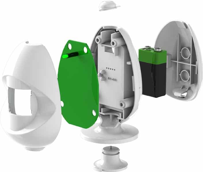
Click to zoom
Application Details
- Equipment Class
- DSC - Part 15 Security/Remote Control Transmitter
- Date of Grant
- Jul 04, 2012
- Application Purpose
- Original Equipment
- Date of Application
- Jul 04, 2012
- Equipment Note
- Wireless controller
- Frequency Range
- 433.92000000 - 433.92000000
- Company
- TreeGreen Limited
- Country
- United Kingdom
Documents & Files
Document Text
Text extracted from the exhibit documents filed with the FCC. Open a document above to read the original.
Users Manual
Dear Customer, Thank you very much for purchasing TreeGreen’s energyEGG®! We hope your product will save you money and energy every day. We need your feedback on the energyEGG® so we can make the product better for customers like yourself. Please reply (positive or negative) via email to [email protected] or call us on 0845 867 5838. Your comments could cover anything from the packaging, instructi ons, website to th e product i ts elf - and if we publish your comments we will send you a £10 voucher for M&S! Please regis ter online at www.treegreen.net to increase your 12 month war ranty to a massive 3 year war ranty. Kind Regards, The TreeGreen Team www.t reegreen.net [email protected] 0845 867 5838 Di gita l Enterpris e Centre CBLZ Buil ding 190 Cathedral St reet Gl asgow, G4 0ND treegreen f follow us at DOC-002-01 v1 SCALE: 1/1 DWG NO. TITLE : Warranty Document DO NOT SCALE DRAWING DEBUR AND BREAK SHARP EDGES UNLESS OTHERWISE SPECIFIED: DIMENSIONS ARE IN MILLIMETERS treegreen Dimensions 124 x 88.5mm Mater ial 190-210gsm gloss white paper Tolerance±0.5mm ArtworkSupplied by TreeGreen Description 88.5mm 124mm Product warranty document to b e inserted into p ackagin g Dear Customer, Thank you very much for purchasing TreeGreen’s energyEGG®! We hope your product will save you money and energy every day. We need your feedback on the energyEGG® so we can make the product better for customers like yourself. Please reply (positive or negative) via email to [email protected] or call us on 0845 867 5838. Your comments could cover anythi ng from t he packagin g, instr uctions, website to th e product itself - and if we publish your comments we will send you a £10 voucher for M&S! Please register o nline at www.treegreen.net to increase your 12 month war ranty to a massive 3 year war ranty. Kind Regards, The TreeGreen Team www.t reegreen.net [email protected] 0845 867 5838 Di gita l Enterpris e Centre CBLZ Buil ding 190 Cathedral St reet Gl asgow, G4 0ND treegreen f follow us at
Users Manual
SO WHAT IS THE energyEGG®? The energyEGG® is a wireless appliance controller. It makes switching o appliances in a room - or around the home - simple. It automatically switches o electrical equipment after you leave the room - saving energy, time and reducing electric bills. It has 3 main functions : ROOM ON/OFF Pressing the Power Button (see Figure 1) switches ON appliances. Pressing and holding the Power Button for 2 seconds switches OFF appliances connected to the Control Adaptor(s) (see Figure 3) in a room. Auto Room OFF When a room is empty for a preset time the energyEGG® (Figure 2) automatically switches OFF connected appliances. HOME OFF Pressing and holding the Power Button for 5 seconds, while appliances are ON, switches OFF all connected appliances around a home. Please note that the maximum range of the energyEGG® may vary depending on the building it is being used in . Power Indicator Control Button Socket Figure 3 Control Adaptor Power Button LED Indicator Battery Compartment Smart Motion Sensor Adjustable Timer on Base Figure 1 The energyEGG® Figure 2 Timer Dial Timer OFF Setting Dial energyEGG® Figure 4: Positioning your energyEGG® 100º 2.5m 3.5m SET UP INSTRUCTIONS (ROOM CONTROL) STEP 1 Plug the Contr ol Adaptor into a mains socket, making sure that the wall socket is switched on. The LED on the Contr ol STEP 2 Insert the batt ery into the energyEGG®. Press the Power Button to signal the Contr ol Adaptor . The LED on the successfully linked with the energyEGG®. Test the Contr ol Adaptor by switching it ON and OFF using the energyEGG® Power Button. STEP 3 When the energyEGG® it detects movement. Place your energyEGG® (See Figure 4) up to 2.5m from where you usually sit, around 1m from the Figure 1) facing you. Test the energyEGG® position by waving your hand and checking that the energyEGG®energyEGG® works best when it is not placed in direct sunlight. STEP 4 Plug in an appliance or power strip to the Contr ol Adaptor . Switch OFF appliances by pressing and holding the button for 2 seconds - the energyEGG® will beep twice to indicate that you can release the button. The 2 second button delay helps prevent accidental switch OFF. STEP 5 To connect an additional Contr ol Adaptor to the energyEGG®, simply repeat these steps. Experiment with the best position for the energyEGG® t o signal all Contr ol Adaptors. Note : To connect an extr a energyEGG® t o a contr ol adaptor , press and hold the button on the Contr ol Adaptor until the light Now press the button on the energyEGG® t o connect it. SET UP INSTRUCTIONS CONTD... STEP 6 Set the timer on the base of the energyEGG®. Remember to give yourself enough time to leave the room, make a cup of tea, and return. This will ensure your appliances are not inconveniently switched OFF. If you do not want the energyEGG® to automatically switch o your appliances set the Timer Dial to the ‘TIMER OFF’ setting (See Figure 2). TreeGreen recommends using a power strip instead of severalControl Adaptors when connecting multiple appliances Note : If you connect your computer to the energyEGG® ensure that the computer is set to go into sleep mode 5 minutes before the energyEGG® timer setting. So if your computer is set to go into sleep mode after 10mins, set the energyEGG® dial to 15mins. TreeGreen takes no responsibility for wrong setup or lost data. TreeGreen recommends that you regularly save and back up your data. ADDITIONAL FEATURES Auto Your energyEGG® automatically turns OFF appliances OFF when you forget. It detects when a room is empty and sends a switch o signal to the Control Adaptor(s) after a preset time (between 5 and 30 mins). Turn the dial to your preferred time delay using the intervals on the base as a reference. ADDITIONAL FEATURES CONTD AUTO OFF The energyEGG® will alert you 1 minute before it switches Alert anything OFF by beeping and ashing the green light. This gives you an opportunity to prevent the AUTO OFF by moving or coming back into the room. Feedback When the energyEGG® automatically switches appliances OFF it lets you know by beeping the next time you enter the room and then ashing the LED green for 1 minute. HOME OFF Switch o Control Adaptors in di erent rooms using a single energyEGG® - by pressing the energyEGG® button for 5s. To set up the HOME OFF function rst ensure that the energyEGG® is in ON mode ( ashes when it detects movement). Then put each control adaptor you want to respond to HOME OFF into ‘learn mode’. Now press and hold the Power button on the energyEGG® for 5 seconds and release. Timer OFF If you wish to deactivate the Auto Room OFF of the energyEGG® and have manual button control only, simply rotate the dial to the OFF’ setting (see Figure 2). Battery If your energyEGG® begins to run out of battery power, it Replacement will beep intermittently for around 5 minutes when Alert you switch it on. If it starts to beep during operation and a detected movement does not stop the beeping then you need to replace the battery. Reset Control To disconnect a Control Adaptor from all energyEGGs®, Adaptor press and hold the button on the Adaptor until it ashes slowly, then ashes quickly. TROUBLESHOOTING Problem: ‘My energyEGG® switches o appliances while I am in the room’ Solution: Should the energyEGG® go into power o mode while you are in the room, reposition the energyEGG® and ensure there are no obstructions to the eld of view. If you use several energyEGGs®, this may be a result of setting up the HOME OFF function incorrectly - if so, repeat the HOME OFF set up instructions. Problem: ‘My energyEGG® does not switch o appliances’ Solution: Should the energyEGG® fail to switch on/o appliances: repeat SET UP INSTRUCTIONS. Should the problem persist, replace the battery. Also Check that the range is within 20m. Problem: ‘My energyEGG® switches my appliances o when I leave the room to make a cup of tea or go to the bathroom’ Solution: Should the energyEGG® switch o appliances when a room is va…
Text truncated - open the document above for the full version.
Users Manual
energyEGG Assembly Instructions v6.0 Version : v6.0 Date : 4 th May 2012 TreeGreen Limited Digital Enterprise Centre, CBLZ Building, 190 Cathedral St Glasgow, G4 OND Stuart Henderson 07941 222 437 [email protected] 1 energyEGG Assembly Instructions Equipment Required Phillips head screwdriver Components 1 x EG-001 : Main Base 1 x EG-002 : Front Case 1 x EG-004 : Rear Case 1 x EG-005 : Button 1 x EG-006 : Dial 1 x Lens 1 x PCB (Printed Circuit Board) 4 x Screws 1 x Compliance Label 2 energyEGG Assembly Instructions 3 energyEGG Assembly Instructions 4 energyEGG Assembly Instructions 5 energyEGG Assembly Instructions 6 energyEGG Assembly Instructions Before beginning assembly please note: - Be careful when handling the PCB(Printed Circuit Board) as touching the Sensor can seriously impair functionality. - Be careful when handling the Lens as it is sensitive and easily scratched – this can significantly diminish the functionality of the lens. Step 1 : Insert Button (EG-005) Insert Button (EG-005) into the slot at the top of the Main Base (EG-001) as shown in Figure 1a. The Button should slide into the ledge as shown in Figure 1b. Figure 1a - Insert Button in Main Base 7 energyEGG Assembly Instructions Figure 1b - Slide Button into Ledge The Button should sit flush in the Main Base when inserted correctly. When inserted correclt, there should be no gap between the Button and Main Base (See Figure 1c). Figure 1c - There should be no gap between Button and Main Base 8 energyEGG Assembly Instructions The Button should also be flush and parallel with the top of the Main Base (See Figure 1d). Figure 1d – Button should fit into the Main Base and not be angled 9 energyEGG Assembly Instructions Step 2 : Prepare PCB The first step of inserting the PCB is to tie a knot in the battery fly wire, around 5cm from the base of the PCB (see figure 2a) Figure 2a - Tie knot in the battery fly lead 10 energyEGG Assembly Instructions Ensure that the Pot on the PCB is in the right position (see Figure 2b). The pot should be slightly angled forward away from the PCB. Figure 2c highlights the correct and incorrect alignment for the Pot. Figure 2b - Pot Alignment Figure 2c – Correct and Incorrect Pot Alignment 11 energyEGG Assembly Instructions Step 3 : Insert PCB Figure 3a shows a step by step guide to inserting the PCB into the Main Base. First thread the battery connector through the gap at the top of the Main Base as show in . Next, place the PCB down onto the Main Base ( ), aligning the four screw holes on the PCB with the screw bosses on the Main Base ( ). Figure 3a - Insert PCB onto Main Base 12 energyEGG Assembly Instructions The PCB should now sit flush and tight against the Main Base as shown in Figure 3b. Please ensure that the PCB is tight against the Main Base at each of the four screw bosses. Figure 3b - PCB should be flush with Main Base and aligned with Button The Button (EG-005) aligns with the red button on the PCB and should ‘click’ when depressed. Figure 3b shows the correct and incorrect alignment of the Button EG-005 to the PCB button. 13 energyEGG Assembly Instructions Step 4 : Insert Dial Before inserting the Dial in the Main Base, please ensure that the blue pot is pointing towards the ‘5’ setting on the Main Base (see Figure 4a). 14 energyEGG Assembly Instructions Now Place the Dial (EG-006) into the bottom of the Main Base (EG-001). The Dial (EG-006) should point to the 5 Minute setting on the Main Base (See Figure 4b). Figure 4b - Dial pointing towards the '5' minute setting When inserted correctly, the Dial should sit tight and flush to the Main Base. 15 energyEGG Assembly Instructions Step 5 : Attach Lens to Front Case Attach the Lens to the Front Case (EG-002), with the smooth, glossy surface facing out. To do so, align the Lens so that chamfered corner is at the top right hand edge of the enclosure and clip into place (Figure 5a). Figure 5a - Ensure the chamfered edge of the Lens is at the top right corner 16 energyEGG Assembly Instructions The Lens should ‘click’ into place at each of the four areas highlighted in Figure 5b. Figure 5b - Lens should 'click' into place. With the Lens correctly attached to the Front Case, apply a small amount of adhesive to hold the lens firmly in place. 17 energyEGG Assembly Instructions Step 5 : Attached Front Case to Main Base Now take the assembled Front Case(EG-002) and the assembled Main Base(EG-001) and piece together (see Figure 5a). The Front Case (EG-002) should fit flush with the Main Base (EG-001) and no components should be loose. If assembled correctly: - The Button (EG-005) should click when pressed and then return to its original position. - The Dial (Eg-006) should be able to rotate freely and click at each setting. - No components should be loose or rattle. Figure 5a - Attach Front Case to Main Base 18 energyEGG Assembly Instructions Step 6 : Insert Screws Whilst holding the assembled EGG together, fasten 4 screws into the back of the Main Base (EG-001) as shown in Figure 6a. Figure 6a - Screw Locations 19 energyEGG Assembly Instructions Now place the Compliance label in the recessed area on the Energy EGG as shown in Figure 6b. The Compliance label should not obstruct the 5 pinholes. The energyEGG is not shipped with the battery pre-installed, and as such, the Compliance Label must be visible to the user. 20 energyEGG Assembly Instructions Step 7 : Attach Rear Case 21 energyEGG Assembly Instructions Now attach the Rear Case (EG-004) to the assembled unit. Firstly, insert the upper clip of the Rear Case into the assembled unit, and then the rest of the case should clip into place (see Figure 7a). 22 energyEGG Assembly Instructions Now set the timer dial to the ’10 minute’ setting as shown in Figure 7c The Energy EGG should now be fully assembled. There are a number of checks you can perform in order to determine whether the Energy EGG is correctly assembled, these include: Testing the Button - the button should be flush with the rest…
Text truncated - open the document above for the full version.
Attestation Statements
Graham Hills Building 50 Richmond Street Glasgow, G1 1XP www.treegreen.net [email protected] 0845 867 5838 26 th June 2012 Dear TÜV SÜD, TreeGreen Ltd. (Company No. : SC333763) hereby states, with regards to the TreeGreen energyEGG (Product Code : EG-W1G02), that: The energyEGG is not shipped with the battery pre-installed and the FCC ID will be readily visible when users open the product box. Sincerely, Managing Director, TreeGreen Ltd.
Cover Letter(s)
ANNEX A Dear Sir or Madam, l, Brian O'Reilly hereby authorize Natalie Bennett of TUV SUD Product Service Ltd, Octagon House, Concorde Way, Segensworth North, Fareham, Hampshire PO15 sRL +44(0X489 558254 to act as our agent in all matters rclating to applications for equipment authorization, including the signing of all documents relating to these matters. This authorization expires on 1Oth November 2012. Sincerely, B"^r^^^Yq Brian O'Reilly Managing Director Gompany Officer: Telephone Number: Email: Brian O'Reilly 07879486787 [email protected] TreeGreen Limited 50 Richmond Street Glasgow, G1 1XP www.treegreen.net enq u i ries@treeg reen.net 0141 4162624 TreeGreen
Cover Letter(s)
TreeGreen TreeGreen Limited 50 Richmond Street G l a s g o w , G 1 1 X P www.treegreen.net [email protected] 0141 416 2624 10/5/2012 BABT Forsyth House Churchfield Road Walton-on-Thames Surrey KT12 2TD Confidentiality Request Pursuant to Sections 0.457(d)(1)(ii) and 0.459 of the Commission’s Rules, TreeGreen Ltd. hereby requests permanent confidential treatment of information accompanying this application as outlined below: - Schematics - Bill of Materials/Parts List - Block Diagrams - Theory of Operation The above materials contain trade secrets and proprietary information not customarily released to the public. The public disclosure of these matters might be harmful to the Applicant and provide unjustified benefits to its competitors. The Applicant understands that pursuant to Rule 0.457(d)(1)(ii), disclosure of this Application and all accompanying materials will not be made before the date of the Grant for this Application. Yours sincerely, Brian O’Reilly Managing Director Company Officer: Brian O’Reilly Telephone Number: 07879 486787 Email: [email protected]
External Photos
treegreen ® Technical Speci cation : EG-W1G02 FEATURES: - LED Indicator - ‘One Touch’ Button - Wirelessly connects to socket - Unique ‘SitStill’ Sensor - Timer Dial on Base CE Compliant RoHS Compliant R&TTE Compliant WEEE Compliant SPECS: Product Weight : 0.101kg Battery Type : PP3 9V No. of Batteries : 1 Battery Chemsitry : Alkaline Transmission Frequency : 433.92MHz Power Consumption (OFF) : 0.54mW Power Consumption (ON) : 0.58mW Detection Range : 10m Trnasmission Range : Up to 30m Region of Use : UK 108mm 65mm 56mm
External Photos
Main Base EG-001 Rear View External Image 1 of 12 Main Base EG-001 Front View External Image 2 of 12 Front Case EG-002 Front View External Image 3 of 12 Front Case EG-002 Rear View External Image 4 of 12 Rear Case EG-004 Rear View External Image 5 of 12 Rear Case EG-004 Front View External Image 6 of 12 Button EG-005 Rear View External Image 7 of 12 Rear View Front View Dial EG-006 Rear View External Image 8 of 12 Dial EG-006 Front View External Image 9 of 12 Exploded View External Image 10 of 12 Assembled View External Image 11 of 12 Assembled View External Image 12 of 12
ID Label/Location Info
TreeGreen EnergyEGG® EG-W3G02 1 x 9V Battery Power Consumption : 0.58W 19.5 22.5 OEM-08 v4 SHEET 1 OF 2 SCALE:1:1 DWG NO. TITLE : Energy EGG Compliance Label REVISION v4 DO NOT SCALE DRAWING UNLESS OTHERWISE SPECIFIED: DIMENSIONS ARE IN MILLIMETERS SURFACE FINISH: Gloss TOLERANCES: N/A LINEAR: N/A ANGULAR: N/A treegreen UNLESS OTHERWISE SPECIFIED: DIMENSIONS ARE IN MILLIMETERS SURFACE FINISH: Gloss Material: Clear Gloss LINEAR: N/A ANGULAR: N/A CUT Additional Notes: - Dashed lines are to be used as cutting guideline and should not be visible on printed label. DESCRIPTION Compliance Label for interior of energyEGG ABS FCC ID : 05CEG-SA TreeGreen EnergyEGG® EG-W3G02 1 x 9V Battery Power Consumption : 0.58W ABS FCC ID : 05CEG-SA 37.7 4.6 OEM-05 v7.0 SHEET 2 OF 2 SCALE:1:1 DWG NO. TITLE : Energy EGG Compliance Label REVISION v7.0 DO NOT SCALE DRAWING UNLESS OTHERWISE SPECIFIED: DIMENSIONS ARE IN MILLIMETERS treegreen UNLESS OTHERWISE SPECIFIED: DIMENSIONS ARE IN MILLIMETERS SURFACE FINISH: Gloss Material: Clear Gloss LINEAR: N/A ANGULAR: N/A Additional Notes: - Dashed lines are to be used as cutting guideline and should not be visible on printed label. DESCRIPTION Compliance Label for interior of energyEGG
Test Report
Document 75915772 Report 04 Issue 1 May 2012 Report On Limited FCC Testing of the TreeGreen Limited EG-SA In accordance with FCC CFR 47 Part 15B COMMERCIAL-IN-CONFIDENCE FCC ID: O5CEG-SA TÜV SÜD Product Service Ltd, Octagon House, Concorde Way, Segensworth North, Fareham, Hampshire, United Kingdom, PO15 5RL Tel: +44 (0) 1489 558100. Website: www.tuvps.co.uk COMMERCIAL-IN-CONFIDENCE Document 75915772 Report 04 Issue 1 Page 1 of 17 COMMERCIAL-IN-CONFIDENCE REPORT ON Limited FCC Testing of the TreeGreen Limited EG-SA In accordance with FCC CFR 47 Part 15B Document 75915772 Report 04 Issue 1 May 2012 PREPARED FOR TreeGreen Limited CBLZ Building 190 Catherdral Street Glasgow G4 0ND PREPARED BY Natalie Bennett Senior Administrator (Technical) APPROVED BY Mark Jenkins Authorised Signatory DATED 23 May 2012 ENGINEERING STATEMENT The measurements shown in this report were made in accordance with the procedures described on test pages. All reported testing was carried out on a sample equipment to demonstrate limited compliance with FCC CFR 47 Part 15B. The sample tested was found to comply with the requirements defined in the applied rules. Test Engineer(s); G Lawler Document 75915772 Report 04 Issue 1 Page 2 of 17 COMMERCIAL-IN-CONFIDENCE COMMERCIAL-IN-CONFIDENCE CONTENTS Section Page No 1 REPORT SUMMARY ................................................................................................................... 3 1.1 Introduction ................................................................................................................................... 4 1.2 Brief Summary of Results ............................................................................................................. 5 1.3 Application Form ........................................................................................................................... 6 1.4 Product Information ...................................................................................................................... 8 1.5 Test Conditions ............................................................................................................................. 8 1.6 Deviations from the Standard ....................................................................................................... 8 1.7 Modification Record ...................................................................................................................... 8 2 TEST DETAILS ............................................................................................................................ 9 2.1 Radiated Emissions .................................................................................................................... 10 3 TEST EQUIPMENT USED ......................................................................................................... 13 3.1 Test Equipment Used ................................................................................................................. 14 3.2 Measurement Uncertainty .......................................................................................................... 15 4 ACCREDITATION, DISCLAIMERS AND COPYRIGHT ............................................................ 16 4.1 Accreditation, Disclaimers and Copyright ................................................................................... 17 Document 75915772 Report 04 Issue 1 Page 3 of 17 COMMERCIAL-IN-CONFIDENCE COMMERCIAL-IN-CONFIDENCE SECTION 1 REPORT SUMMARY Limited FCC Testing of the TreeGreen Limited EG-SA In accordance with FCC CFR 47 Part 15B Document 75915772 Report 04 Issue 1 Page 4 of 17 COMMERCIAL-IN-CONFIDENCE COMMERCIAL-IN-CONFIDENCE 1.1 INTRODUCTION The information contained in this report is intended to show verification of the Limited FCC Testing of the TreeGreen Limited EG-SA to the requirements of FCC CFR 47 Part 15B. Objective To perform Limited FCC Testing to determine the Equipment Under Test's (EUT’s) compliance with the Test Specification, for the series of tests carried out. Manufacturer TreeGreen Limited Model Number(s) EG-SA01G01-01 Serial Number(s) Not Serialised (TSR0015) Number of Samples Tested 1 Test Specification/Issue/Date FCC CFR 47 Part 15B (2010) Incoming Release Date Application Form 6 March 2012 Disposal Reference Number Date Held Pending Disposal Not Applicable Not Applicable Order Number Date Not Applicable Not Applicable Start of Test 31 March 2012 Finish of Test 31 March 2012 Name of Engineer(s) G Lawler Document 75915772 Report 04 Issue 1 Page 5 of 17 COMMERCIAL-IN-CONFIDENCE COMMERCIAL-IN-CONFIDENCE 1.2 BRIEF SUMMARY OF RESULTS A brief summary of the tests carried out in accordance with FCC CFR 47 Part 15B is shown below. Section Spec Clause Test Description Result Comments/Base Standard Idle - Wire Antenna 2.1 15.109 Radiated Emissions Pass Document 75915772 Report 04 Issue 1 Page 6 of 17 COMMERCIAL-IN-CONFIDENCE COMMERCIAL-IN-CONFIDENCE 1.3 APPLICATION FORM APPLICANT'S DETAILS COMPANY NAME : ......Treegreen Limited........................................................................... ADDRESS : .........15 Park Way, Kildrum, Cumbernauld, G67 2BT ................................................................................. ................................................................................. NAME FOR CONTACT PURPOSES : ..............Brian O’Reilly............................................................ TELEPHONE NO: ....................................... FAX NO: ....................................... E-MAIL: 07879 486787............... EQUIPMENT INFORMATION Model name/number ......EG-SA.................. Identification/Part number ......EG-SA.................. Hardware Version .........3.4............... Software Version ......1.8.................. Manufacturer .........Semecs............... Country of Origin ......Slovakia.................. FCC ID .........O5CEG-SA............... Industry Canada ID ......N/A.................. Technic…
Text truncated - open the document above for the full version.
Test Report
Document 75915772 Report 05 Issue 1 May 2012 Report On Limited FCC Testing of the TreeGreen Limited EG-SA In accordance with FCC CFR 47 Part 15C COMMERCIAL-IN-CONFIDENCE FCC ID: O5CEG-SA TÜV SÜD Product Service Ltd, Octagon House, Concorde Way, Segensworth North, Fareham, Hampshire, United Kingdom, PO15 5RL Tel: +44 (0) 1489 558100. Website: www.tuvps.co.uk COMMERCIAL-IN-CONFIDENCE Document 75915772 Report 05 Issue 1 Page 1 of 21 COMMERCIAL-IN-CONFIDENCE REPORT ON Limited FCC Testing of the TreeGreen Limited EG-SA In accordance with FCC CFR 47 Part 15C Document 75915772 Report 05 Issue 1 May 2012 PREPARED FOR TreeGreen Limited CBLZ Building 109 Cathedral Street Glasgow G4 0ND PREPARED BY Natalie Bennett Senior Administrator (Technical) APPROVED BY Mark Jenkins Authorised Signatory DATED 23 May 2012 ENGINEERING STATEMENT The measurements shown in this report were made in accordance with the procedures described on test pages. All reported testing was carried out on a sample equipment to demonstrate limited compliance with FCC CFR 47 Part 15C. The sample tested was found to comply with the requirements defined in the applied rules. Test Engineer(s); R Henley G Lawler Document 75915772 Report 05 Issue 1 Page 2 of 21 COMMERCIAL-IN-CONFIDENCE COMMERCIAL-IN-CONFIDENCE CONTENTS Section Page No 1 REPORT SUMMARY ................................................................................................................... 3 1.1 Introduction ................................................................................................................................... 4 1.2 Brief Summary of Results ............................................................................................................. 5 1.3 Application Form ........................................................................................................................... 6 1.4 Product Information ...................................................................................................................... 8 1.5 Test Conditions ............................................................................................................................. 8 1.6 Deviations from the Standard ....................................................................................................... 8 1.7 Modification Record ...................................................................................................................... 8 2 TEST DETAILS ............................................................................................................................ 9 2.1 Manually Operated Transmitter .................................................................................................. 10 2.2 Field Strength of Emissions ........................................................................................................ 11 2.3 20dB Bandwidth .......................................................................................................................... 15 3 TEST EQUIPMENT USED ......................................................................................................... 17 3.1 Test Equipment Used ................................................................................................................. 18 3.2 Measurement Uncertainty .......................................................................................................... 19 4 ACCREDITATION, DISCLAIMERS AND COPYRIGHT ............................................................ 20 4.1 Accreditation, Disclaimers and Copyright ................................................................................... 21 Document 75915772 Report 05 Issue 1 Page 3 of 21 COMMERCIAL-IN-CONFIDENCE COMMERCIAL-IN-CONFIDENCE SECTION 1 REPORT SUMMARY Limited FCC Testing of the TreeGreen Limited EG-SA In accordance with FCC CFR 47 Part 15C Document 75915772 Report 05 Issue 1 Page 4 of 21 COMMERCIAL-IN-CONFIDENCE COMMERCIAL-IN-CONFIDENCE 1.1 INTRODUCTION The information contained in this report is intended to show verification of the Limited FCC Testing of the TreeGreen Limited EG-SA to the requirements of FCC CFR 47 Part 15C. Objective To perform Limited FCC Testing to determine the Equipment Under Test's (EUT’s) compliance with the Test Specification, for the series of tests carried out. Manufacturer TreeGreen Limited Model Number(s) EG-SA01G01-01 Serial Number(s) Not Serialised (TSR0015) Number of Samples Tested 1 Test Specification/Issue/Date FCC CFR 47 Part 15C (2011) Incoming Release Date Application Form 6 March 2012 Disposal Reference Number Date Held Pending Disposal Not Applicable Not Applicable Order Number Date Not Applicable Not Applicable Start of Test 12 February 2012 Finish of Test 13 April 2012 Name of Engineer(s) R Henley G Lawler Related Document(s) ANSI C63.10: 2009 Document 75915772 Report 05 Issue 1 Page 5 of 21 COMMERCIAL-IN-CONFIDENCE COMMERCIAL-IN-CONFIDENCE 1.2 BRIEF SUMMARY OF RESULTS A brief summary of the tests carried out in accordance with FCC CFR 47 Part 15C is shown below. Section Spec Clause Test Description Result Comments/Base Standard Transmit - Wire Antenna 2.1 15.231 (a)(1) Manually Operated Transmitter Pass 2.2 15.231 (b) Field Strength of Emissions Pass 2.3 15.231 (c) 20dB Bandwidth Pass Document 75915772 Report 05 Issue 1 Page 6 of 21 COMMERCIAL-IN-CONFIDENCE COMMERCIAL-IN-CONFIDENCE 1.3 APPLICATION FORM APPLICANT'S DETAILS COMPAN…
Text truncated - open the document above for the full version.
Contact Information
Applicant
Brian O'Reilly(Managing Director)
Test Firm
TUV SUD Product ServiceMark Jenkins
Technical Specifications
| # | Rule Parts | Frequency Range | Power Output |
|---|---|---|---|
| 1 | 15.231 | 433.92 MHz - 433.92 MHz | 1.00 mW |