O5NURSATMAX3UIRIDSatellite Media Access Extender
Universal Repeater, LLC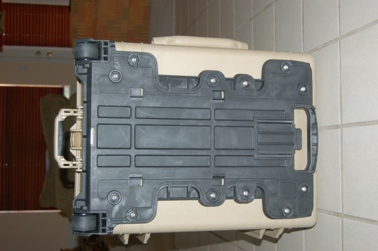
Click to zoom
Application Details
- Equipment Class
- BOS - All other signal boosters other than 20.21/90.219
- Date of Grant
- Feb 19, 2015
- Application Purpose
- Original Equipment
- Date of Application
- Feb 19, 2015
- Equipment Note
- Satellite Media Access Extender
- Frequency Range
- 1616.00000000 - 1626.50000000
- Company
- Universal Repeater, LLC
- Country
- United States
Documents & Files
Document Text
Text extracted from the exhibit documents filed with the FCC. Open a document above to read the original.
Users Manual
Universal Repeater LLC Satellite Media Access Extender 1 Users Manual 2 Satellite Media Access Extender (SatMAXTM) repeater is an exclusive, advanced communications system that offers, true “total” global voice and data communications coverage for multiple simultaneous users (for up to 3 simultaneous users) in non-line-of-sight environments (i.e. indoors). Utilizing SatMAX technology, the SatMAXTM receives multiple non-line-of- sight RF signals, amplifies those signals, and rebroadcasts them to and from the global satellite constellation. The network then broadcasts those signals to and from the intended recipients within a building/ship/hangar or non line of site locations. Traditionally, low-Earth-orbit satellite communications networks such as Iridium ® require line-of-sight to an orbiting satellite. These systems typically require the user to be outdoors with a clear view of the sky in order to make a voice or data call. For example, with the SatMAX TM , users with a standard Iridium ® handset can send and receive voice and data calls on an aircraft, in a building, or from virtually any location where it is difficult to physically gain line-of-sight to an orbiting Iridium® satellite .The SatMAX unit is ideally suited for both routine, everyday applications, as well as mission-critical communications. The SatMAX unit enables highly reliable voice and data communications beyond the reach of cellular networks and extends satellite communications coverage to areas not traditionally available for service, including: Above or below deck on ships Within commercial buildings Within Aircraft Hangars On board vehicles From obstructed areas Within Disaster Recovery Control Centers 1.1 Introduction This document covers the Universal Repeater SatMAX repeater 3 models and packaging configurations, fixed structure and portable versions for commercial, government and military applications. It is intended to be used to explain the functionality of the SatMAX products in conjunction with the Iridium Network. This solution can be used for data communications coverage to both large and small groups of simultaneous users within buildings/ fixed structures, in obstructed areas, underground and in dense metropolitan areas. The Universal Repeater SatMAX unit is available as a portable version and 3 user group sizes for airborne, sea and ground-based applications. SatMAX Portable Figure 1 Portable Models: Model # Portable-003, The Portable-xxx model of the SatMAXTM is intended for nonline-of-sight 4 applications requiring portability, battery operation, as well as rapid setup and installation. Equipment Description The SatMAX satellite repeater is designed for use with the satellite constellations to serve as a lightweight, high- capacity, high-reliability, satellite repeater. For example, a typical system level application of the SatMAXTM repeater in conjunction with the Iridium® network is shown in Figure-1. Package and User-Size Options All SatMAXTM models are available in a variety of packaging and user-size options to suit the various user requirements. The packaging option here is a pelican case portable enclosure, complete with deployable coaxial cable and antennas. This unit comes with a rechargeable battery power source that may be recharged from either standard AC power or a vehicle DC power source. SatMAXTM-003 The L-Band SatMAXTM is designed to serve as a lightweight, high-capacity, high-reliability, satellite repeater to provide satellite communications for up to three concurrent users in locations where the user cannot directly receive the satellite signal. Typical usage would be in buildings, aircraft, underground, or in locations where it would be difficult to go outside to utilize a satellite telephone. Portable SatMAXTM-003 is a high-performance L- band satellite link repeater housed in a lightweight, but rugged, easily transportable rugged suitcase style assembly. The unit comes fully self- contained with two exterior antennas that deploy, along with their easily 5 connected low-loss coaxial cables. Deployment is as simple as connecting the coaxial cables and placing the antennas in a convenient location where they have an unobstructed view of the sky. The interior antennas and their associated coaxial cables are included in the suitcase and, after deployment, are pointed in the direction where repeat of the signal is required. The unit is powered from a built-in rechargeable power source or alternatively, may be powered from standard electrical power. For example, this unit is ideal for non- permanent locations requiring interior Iridium® satellite communications when installation and setup time is limited. Normal usage is with any standard Iridium® handset. Mechanical & Packaging Weight: approximately 39 Pounds Packaging: Custom Pelican Case Enclosure SatMAXTM-003: RF Characteristics Up-Link/Down-Link (Link between SatMAXTM and Iridium® Satellite) Output Frequency Range: 1616-1626.5 MHz Output Power: (at –1dB Gain Compression) +37.0 dBm Input Frequency Range: 1616-1 626.5 MHz Signal Bandwidth: 10.5 MHz Minimum Input Power: (MDS) -118.5 dBm Overall Gain: +92 dB Gain Variation: N/A Gain Flatness: Over any 2 MHz Bandwidth: +/- 0.4 dB Over any 10MHz Bandwidth: +/- 0.5 dB Spurious Outputs @ 37 dBm Output Power: -40 dBc, max Harmonics @ 37 dBm Output Power: -60 dBc, max VSWR (Input & Output): 1.8:1 Voltage Input: +15 VDC 6 DC Consumption: 42 Watts Repeater Link (Link between SatMAXTM and Iridium® Handsets) Input Frequency Range: 1616-1 626.5 MHz Output Power (at –1dB Gain Compression): +10 dBm Output Frequency Range: 1616-1626.5 MHz Signal Bandwidth: 10.5 MHz Minimum Input Power (MDS): -118.5 dBm Overall Gain: +76 dB Gain Variation: N/A Gain Flatness: Over any 2 MHz Bandwidth: +/- 0.4 dB Over any 10MHz Bandwidth: +/- 0.5 dB Overall Noise Figure: 2.0 dB, max Image Rejection: >50 dB Harmonics: -45 dBc VSWR: 1.8:1 Standard Antenna (Iridium ® Band) Specifications and Features Physical …
Text truncated - open the document above for the full version.
External Photos
14426 O5NURSATMAX3UIRID Page 1 of 6 Side 1: Top View – Handle Extended 14426 O5NURSATMAX3UIRID Page 2 of 6 Side 2: Left - Wheels 14426 O5NURSATMAX3UIRID Page 3 of 6 Side 3: Right 14426 O5NURSATMAX3UIRID Page 4 of 6 Side 4: Hinge-End View – External Connectors 14426 O5NURSATMAX3UIRID Page 5 of 6 Side 5: Front View – Latch Side 14426 O5NURSATMAX3UIRID Page 6 of 6 Side 6: Bottom View ***
Internal Photos
14426 – Cavity Filter Photos FCC ID O5NURSATMAX3UIRID Page 1 of 3 14426 – Cavity Filter Photos FCC ID O5NURSATMAX3UIRID Page 2 of 3 14426 – Cavity Filter Photos FCC ID O5NURSATMAX3UIRID Page 3 of 3 ***
Internal Photos
14426 O5NURSATMAX3UIRID Page 1 of 11 Internal Photographs Contents Figure 1 - Before Disassembly – Front Panel / Us er Cont rols ................................................................... ....................................................................................................................... 2 Figure 2 - Front Panel Removed - Main Sections Visibl e - Shields On ........................................................... ................................................................................................................. 3 Figure 3 - Front Panel Back Side - Powe r Switch and Power Entry / Controls .................................................... ............................................................................................................ 4 Figure 4 - Internal View - Main Item s Labeled ................................................................................. ............................................................................................................................... 5 Figure 5 - Power Amp Shield Removed - Charge Cont roller Lifted to Reveal Low Noise Amps (LNAs) ................................ ...................................................................................... 6 Figure 6 - Beginning Reemoval of Shields ...................................................................................... ............................................................................................................................... .. 7 Figure 7 - High Level View with Shields Rem oved, Note that Black Filters are Sealed ........................................... ....................................................................................................... 8 Figure 8 - Power Supply M odule - Close Up View ................................................................................ .......................................................................................................................... 9 Figure 9 - Power Amp - Close Up View .......................................................................................... ............................................................................................................................... 10 Figure 10 - One of 3 Identical Low Noise Amplifiers - Close Up View ........................................................... ............................................................................................................. 11 14426 O5NURSATMAX3UIRID Page 2 of 11 Figure 1 - Before Disassembly – Front Panel / User Controls 14426 O5NURSATMAX3UIRID Page 3 of 11 Figure 2 - Front Panel Removed - Ma in Sections Visible - Shields On 14426 O5NURSATMAX3UIRID Page 4 of 11 Figure 3 - Front Panel Back Side - Power Switch and Power Entry / Controls 14426 O5NURSATMAX3UIRID Page 5 of 11 Figure 4 - Internal View - Main Items Labeled 14426 O5NURSATMAX3UIRID Page 6 of 11 Figure 5 - Power Amp Shield Removed - Charge Cont roller Lifted to Reveal Low Noise Amps (LNAs) 14426 O5NURSATMAX3UIRID Page 7 of 11 Figure 6 - Beginning Removal of Shields 14426 O5NURSATMAX3UIRID Page 8 of 11 Figure 7 - High Level View with Shields Rem oved, Note that Blac k Filters are Sealed 14426 O5NURSATMAX3UIRID Page 9 of 11 Figure 8 - Power Supply Module - Close Up View 14426 O5NURSATMAX3UIRID Page 10 of 11 Figure 9 - Power Amp - Close Up View 14426 O5NURSATMAX3UIRID Page 11 of 11 Figure 10 - One of 3 Identical Low Noise Amplifiers - Close Up View ***
RF Exposure Info
14426-15 Exposure Report Page 1 of 2 Maximum Permissible Exposure Evaluation The results of power measurement and inclusion of antenna gain are weighed against the requirements for safety of RF exposure. Criteria FCC Part 2 excludes RF safety evaluation if the effective radiated power (ERP) is below threshold levels cited in the reference clause as shown below: Section Reference Evaluation Threshold Parameter Date 2.1091(c), OET Bulletin 65 Part 25 Device 1 : 3 W ERP, Operating Frequency > 1.5 GHz January 31, 2014 1 This device operates at 1.6 GHz such that the FCC 2.1091(c) criteria for Part 25 devices apply as follows: “... operate at frequencies above 1.5 GHz and their ERP is 3 watts or more.” Procedure Apply antenna gain to the measured conducted transmit power to determine ERP. Then compare ERP to the threshold parameter. If the calculated ERP is under the threshold then no further action is required. Exceeding the threshold requires additional evaluation or testing as determined by applying the FCC guidance document. Results Antennas for this device are located in two basic areas: uplink/outdoors (roof generally), and downlink/indoors (ceiling on lower floors typically). This prevents co-location of the transmit antennas. Outdoors, the uplink transmit antenna is placed for the best sky angle. Indoors, the downlink transmit antenna is located for best area coverage but must be kept at a significant distance from the receive antenna for the uplink amplifier. This EUT has two transmit ports with a single antenna for each. All transmit and receive ports use the same antenna. The highest output power port frequency for each amplifier is evaluated below. The power is based on each amplifier operating at saturation as worse case. Iridium uses FDMA/TDMA technology and the design has a limit on transmit duty cycle of 9.2%. 1 Considering the number of users at 3, the factor applied is -5.59 dB. The uplink antenna requires mounting on the roof by skilled technicians. The evaluation is then for General Public Uncontrolled Exposure and at a distance of 1 m. 1 http://www.decodesystems.com/iridium.html was referenced for technical information on Iridium, which includes the following statement on power: "RF Power Output: Variable range from 0.1 to 0.6 Watts (by control of satellite network via closed loop power control). The transmitter duty cycle allows for bursted transmission every 8.28 ms out of 90 ms, or 9.2%, at a rate of 50 kbps, or 25 k symbols/sec." Assuming 3 concurrent users for each 8.28 ms time slot, total transmit time is 8.28 * 3 or 24.84 ms in 90 ms. When converted to log units as 10 * log 10 (24.84/90) yields a factor of -5.59 dB. 14426-15 Exposure Report Page 2 of 2 Uplink Conducted Transmit Power Measured Including Antenna Gain Iridium Maximum Duty Cycle Specification Power Factoring In Duty Cycle ERP Threshold Per FCC 2.1091(c) Excluded From RF Exposure Limitation? 19.1 W ‐5.59 dB 5.26 W 3 W No The field density limits are determined as: 1.0 mW/cm 2 Ref. FCC Bulletin OET-65 Table 1(B) The uplink field density is determined at 100 cm: S = EIRP / (4 π 100 2 ) Ref. FCC Bulletin OET-65 Equation (4) S = 5260.0 mW / 125663.7 cm 2 S = 0.042 mW/cm 2 The uplink field density level is below the respective limit at 100 cm and it therefore meets the criteria for exclusion from SAR testing. Downlink Conducted Transmit Power Measured Including Antenna Gain Iridium Maximum Duty Cycle Specification Power Factoring In Duty Cycle ERP Threshold Per FCC 2.1091(c) Excluded From RF Exposure Limitation? 0.0676 W ‐5.59 dB 0.0187 W 3 W Yes* *Regardless, the exposure is calculated below anyway. The field density limits are determined as: 1.0 mW/cm 2 Ref. FCC Bulletin OET-65 Table 1(B) The downlink field density is determined at 20 cm: S = EIRP / (4 π 20 2 ) Ref. FCC Bulletin OET-65 Equation (4) S = 18.7 mW / 5026.55 cm 2 S = 0.0173 mW/cm 2 The downlink field density level is below the respective limit at 20 cm and it therefore meets the criteria for exclusion from SAR testing. ***
Test Report
1601 North A.W. Grimes Blvd., Suite B Round Rock, TX 78665 e-mail: [email protected] (512) 244-3371 Fax: (512) 244-1846 February 6, 2015 F. Scott Yeager Universal Repeater P.O. Box 912 Llano, TX 78743 Dear Scott: Thank you for allowing Professional Testing (EMI), Inc. an opportunity to perform testing for Universal Repeater LLC. Enclosed is the Wireless Certification Report for the SatMAX. This report can be used to demonstrate compliance with FCC requirements for wireless devices in the United States. If you have any questions, please contact me. Sincerely, Jeffrey A. Lenk President Attachment Wireless Certification Report for the SatMAX Transceiver by Universal Repeater LLC 14426-10 Page 2 of 57 Project 14426-10 SatMAX Wireless Certification Report Prepared for: Universal Repeater LLC By Professional Testing (EMI), Inc. 1601 North A.W. Grimes Blvd., Suite B Round Rock, Texas 78665 February 6, 2015 Written by Eric Lifsey Test Engineer Wireless Certification Report for the SatMAX Transceiver by Universal Repeater LLC 14426-10 Page 3 of 57 Revision History Revision Number Description Date 00 Draft 2 April 22, 2013 03 Revised to ACB comments February 11, 2014 04 Revised per ACB comments March 7, 2014 05 Revised per ACB comments September 5, 2014 06 Revised per ACB comments February 6, 2015 Wireless Certification Report for the SatMAX Transceiver by Universal Repeater LLC 14426-10 Page 4 of 57 Table of Contents Revision History ............................................................................................................................................................. 3 Certificate of Compliance ............................................................................................................................................. 6 1.0 Introduction.......................................................................................................................................................... 7 1.1 Scope ............................................................................................................................................................... 7 1.2 EUT Description ............................................................................................................................................. 7 1.3 EUT Operation ................................................................................................................................................ 7 1.4 Modifications to Equipment ............................................................................................................................ 8 1.5 Test Site .......................................................................................................................................................... 8 2.0 Applicable Documents and Clauses ..................................................................................................................... 9 3.0 Conducted Output Power ................................................................................................................................... 10 3.1 Test Procedure .............................................................................................................................................. 10 3.2 Test Criteria .................................................................................................................................................. 10 3.3 Test Results ................................................................................................................................................... 10 3.3.1 Uplink .................................................................................................................................................. 11 3.3.2 Downlink ............................................................................................................................................. 11 3.3.3 Antenna ............................................................................................................................................... 12 4.0 Spurious Emission Low Edge ............................................................................................................................ 13 4.1 Test Procedure .............................................................................................................................................. 13 4.2 Test Criteria .................................................................................................................................................. 13 4.3 Test Results ................................................................................................................................................... 14 4.3.1 Uplink .................................................................................................................................................. 14 4.3.2 Downlink ............................................................................................................................................. 16 5.0 Spurious Emissions at Antenna Terminals ........................................................................................................ 18 5.1 Test Procedure .............................................................................................................................................. 18 5.2 Test Criteria .................................................................................................................................................. 18 5.3 Test Results ................................................................................................................................................... 18 5.3.1 Uplink .................................................................................................................................................. 19 5.3.2 Downlink .....................................................................................................…
Text truncated - open the document above for the full version.
Test Setup Photos
14426 O5NURSATMAX3UIRID Page 1 of 4 Conducted Output Tests (Power, BW, Spurious) Conducted Output Tests (Power, BW, Spurious) 14426 O5NURSATMAX3UIRID Page 2 of 4 Radiated Spurious Tests Radiated Spurious Tests 14426 O5NURSATMAX3UIRID Page 3 of 4 Signal Source for Radiated Spurious Tests Mains Conducted Emission Test 14426 O5NURSATMAX3UIRID Page 4 of 4 Mains Conducted Emission Test Table Mains Conducted Emission Test Back ***
Contact Information
Applicant
Kevin L Jackson(Owner)
Technical Contact
Professional Testing (EMI), Inc.Eric B Lifsey
[email protected]5122443371
1601 N A W Grimes Blvd · Round Rock, Texas · United States
Non-Technical Contact
Universal Repeater, LLCF Scott Yeager
[email protected]5125351432
Test Firm
Professional TestingRobert McCollough Lenk
Technical Specifications
| # | Rule Parts | Frequency Range | Power Output | Emission | Tolerance |
|---|---|---|---|---|---|
| 2 | 25 | 1.62 GHz - 1.63 GHz | 6.92 W | Q7W | Amp |