O5SWS1Hand Held Voting Station
International Roll-Call Corp.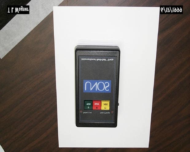
Click to zoom
Application Details
- Equipment Class
- DXT - Part 15 Low Power Transceiver, Rx Verified
- Date of Grant
- Apr 26, 2001
- Application Purpose
- Original Equipment
- Date of Application
- Jul 25, 2000
- Equipment Note
- Hand Held Voting Station
- Frequency Range
- 418.00000000 - 418.00000000
- Country
- United States
Documents & Files
Document Text
Text extracted from the exhibit documents filed with the FCC. Open a document above to read the original.
Block Diagram
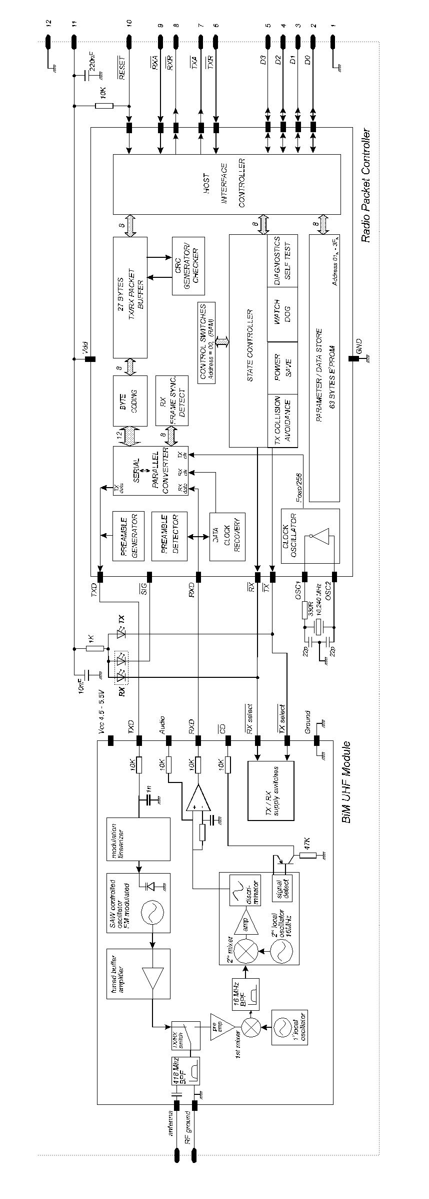
11mz Microcomputer and EEPROM 418mz Radio packet controller 3 votl to 5 volt Power supply Watch dog circuit Switch and LED Module Block diagram of IRC WS1 wireless voting unit 6 inch attenna
External Photos
WS1 external Photo
ID Label/Location Info
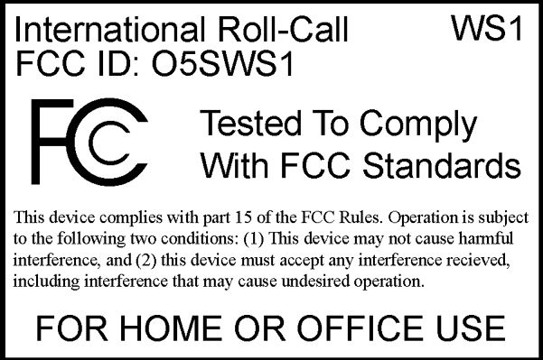
WS1 Fcc label placement
Internal Photos
WS1 internal photo 1
Internal Photos
WS1 internal photo 2
Internal Photos
WS1 PC board front
Operational Description
_____________________________________________________________________ Radiometrix Ltd, RPC page 1 Radiometrix Limited Issue 4, 13 th February 1998RPC-UHF Radio Packet Controller • SAW controlled FM transmitter and superhet receiver • Reliable 30 meter in-building range, 120m open ground • Built-in self-test / diagnostics / status LED’s • Complies with ETSi 300-220 regulations • Single 5V supply @ < 20mA • 40kbit/s half duplex • Free format packets of 1 - 27 bytes • Packet framing and error checking are user transparent • Collision avoidance (listen before transmit) • Direct interface to 5V CMOS logic • Power save mode INTRODUCTION The RPC is a self-contained plug-on radio port which requires only a simple antenna, 5V supply and a byte-wide I/O port on a host microcontroller (or bi-directional PC port). The module provides all the RF circuits and processor intensive low level packet formatting and packet recovery functions required to inter-connect an number of microcontrollers in a radio network. A data packet of 1 to 27 bytes downloaded by a Host microcontroller into the RPC's packet buffer is transmitted by the RPC’s transceiver and will "appear" in the receive buffer of all the RPC's within radio range. A data packet received by the RPC’s transceiver is decoded, stored in a packet buffer and the Host microcontroller signalled that a valid packet is waiting to be uploaded. Modules: RPC-418-A:IC+BiM, UK version RPC-433-A:IC+BiM, Euro version IC’s: RPC-000-DIL:18 pin DIL IC RPC-000-SO:18 pin SO IC The RPC-418-A and RPC-433-A are intelligent transceiver modules which enable a radio network/link to be simply implemented between a number of digital devices. The module combines a UHF radio transceiver and a 40kbit/s packet The RPC-module figure 1: RPC + Host μμ-controller _____________________________________________________________________ Radiometrix Ltd, RPC page 2 _____________________________________________________________________ Radiometrix Ltd, RPC page 3 1. FUNCTIONAL DESCRIPTION On receipt of a packet downloaded by the Host, the RPC will append to the packet: Preamble, start byte and a error check code. The packet is then coded for security and mark:space balance and transmitted through the BiM Transceiver as a 40kbit/s synchronous stream. One of four methods of collision avoidance (listen before TX) may be user selected. When not in transmit mode, the RPC continuously searches the radio noise for valid preamble. On detection of preamble, the RPC synchronises to the in-coming data stream, decodes the data and validates the check sum. The Host is then signalled that a valid packet is waiting to be unloaded. The format of the packet is entirely of the users determination except the 1st byte (the Control Byte) which must specify the packet type (control or data) and the packet size. A valid received packet is presented back to the host in exactly the same form as it was given. To preserve versatility, the RPC does not generate routing information (i.e. source/ destination addresses) nor does it handshake packets. These network specific functions should be performed by the host. Additional features of the RPC include extensive diagnostic/debug functions for evaluation and debugging of the radio and host driver software, a built in self test function and a sleep mode / wake-up mechanism which may be programmed to reduce the average current to less than 100μA. The operating parameters are fully programmable by the host and held in EEPROM, the host may also use the EEPROM as a general purpose non-volatile store for addresses , routing information etc. 1.1 OPERATING STATES The RPC is has four normal operating states: • IDLE / SLEEP • HOST TRANSFER • TRANSMIT • RECEIVE IDLE/SLEEP The IDLE state is the quiescent/rest state of the RPC. In IDLE the RPC enables the receiver and continuously searches the radio noise for message preamble. If the power saving modes have been enabled the RPC will pulse the receiver on, check for preamble and go back to SLEEP if nothing is found. The 'ON' time is 5ms, OFF time is programmable in the RPC’s EEPROM and can vary between 22ms and 2.9s. The TX Request line from the Host is constantly monitored and will be acted upon if found active (low). A TX Request will immediately wake the RPC up from SLEEP mode. HOST TRANSFERS If the host sets the TX Request line low a data transfer from the Host to the RPC will be initiated. Similarly the RPC will pull RX Request low when it requires to transfer data to the Host (this may polled or used to generate a Host interrupt ). The transfer protocol is fully asynchronous, i.e. the host may service another interrupt and then continue with the RPC transfer. It is desirable that all transfers are completed quickly since the radio transceiver is disabled until the Host <> RPC transfer is completed. Typically a fast host can transfer a 27 byte packet to / from the RPC in under 1ms. _____________________________________________________________________ Radiometrix Ltd, RPC page 4 TRANSMIT On receipt of a data packet from the host, the RPC will append to the packet - preamble, frame sync byte and an error check sum. The packet is then coded for mark:space balance and transmitted. A full 27 byte packet is transmitted in 13.8ms of TX air time (40kb/s + 5ms preamble). Collision avoidance (Listen Before Transmit-LBT) functions can be enabled to prevent loss of packets. Data packets may be sent with either normal or extended preamble. Extended preamble is used if the remote RPC is in power save mode. Extended preamble length can be changed in the EEPROM memory. RECEIVE On detection of preamble from the radio receiver, the RPC will phase lock, decode and error check the incoming synchronous data stream and if successful. The data is then placed in a buffer and the RX Request line is pulled low to signal to the host that a valid packet awaits to be uploaded to the Host. An in-coming data packet is presented back to the host in the same for…
Text truncated - open the document above for the full version.
Operational Description
Unit1 Unit 2 Unit 3 Unit 40 Poll Req. AB C DEFG Poll Requst Packet ( A-> B ) = 53.9 ms Slave Response Packet ( C-> D ) = 5.2 ms Guard band ( D->E ) = 1.5 ms Time Div. Multiplex window (C-> G ) = 228 ms Lamp Update Packet (H-> I ) = 53.9 ms Delay between Update Packet (I -> J ) = 1.5 ms Overall Poll Cycle (A -> M ) = 300ms to 2.5 s typical 500 ms Lamp update 1 Unit 0 Poll r eq. Timing Diagram WS-1 International Roll-Call Corp. 8346 Old Richfood Rd. Mechanicsville VA 23116 804 730 9600 Lamp update 2 HIJK LM lamp update 40
Schematics
87654321 A B C D 1 2345678 D C B A Date: June 2, 1999Sheet 1of 1 SizeDocument NumberREV AIRCMAIN.JOB Title INT'L ROLL CALL RF LINK MAIN BOARD Chesapeake, VA 23322 3140 Bunch Walnuts Rd. Electronic Devices Inc. GND 1 D0 2 D1 3 D2 4 D3 5 TXR_ 6 TXA_ 7 RXR_ 8 RXA_ 9 RES_ 10 VCC 11 GND 12 P1 RPC-418A D3 1N914 VCC NIC 1 P1.0/T2 2 P1.1/T2EX 3 P1.2/ECI 4 P1.3/CEX0 5 P1.4/CEX1 6 P1.5/CEX2 7 P1.6/CEX3 8 P1.7/CEX4 9 RST 10 P3.0/RXD 11 NIC 12 P3.1/TXD 13 P3.2/I0_ 14 P3.3/I1_ 15 P3.4/T0 16 P3.5/T1 17 P3.6/WR_ 18 P3.7/RD_ 19 XTAL2 20 XTAL1 21 VSS 22 NIC 23 P2.0/A8 24 P2.1/A9 25 P2.2/A10 26 P2.3/A11 27 P2.4/A12 28 P2.5/A13 29 P2.6/A14 30 P2.7/A15 31 PSEN_ 32 ALE 33 NIC 34 EA_/VPP 35 P0.7/AD7 36 P0.6/AD6 37 P0.5/AD5 38 P0.4/AD4 39 P0.3/AD3 40 P0.2/AD2 41 P0.1/AD1 42 P0.0/AD0 43 VCC 44 U1 89C51RC+ SW1 SW2 R5 4.7 K VCC GND 1 DATA 2 N/C 3 U2 DS2401 SW1 RESET R3 430 K VCC R6 1K RXD SW3 LED1 LED2 LED3 LED4 LED5 RXR_ 1 2 3 4 5 6 J4 PGM RXD TXD VCC C17 .1uF DIP2 DIP3 DIP4 DIP5 DIP6 DIP7 DIP8 DIP1 LBO_ RXR_ TXD DIAG VCC RST_ 1 GND 2 SRT 3 SWT 4 WDS 5 WDI 6 RST 7 VCC 8 U3 MAX6304 R4 150 K C6 0.1 uf C7 0.22 uf C5 33pF C4 33pF Y1 11.059 SWTSW1 LED1 LED4 1 2 3 4 5 6 7 8 9 10 11 12 13 14 15 16 J1 SIG DIP1 DIP2 DIP3 DIP4 DIP5 DIP6 DIP7 DIP8 LED2 1 2 3 4 5 6 7 8 9 10 11 12 13 14 15 16 J2 PWR VCCD2 1N5817 L1 22uH SW SHOWN IN EXTENDED POS. R1 300 K C1 150uF D1 1N5817 SW2 PWR SW C16 .1uF 1 2 J3 BATT R2 680 K C2 100uF C8 .1uF SW2 SW3 LED3 LED5 DIAG 1 2 JP1 JUMPER MH2MH1 SHDN_ 1 3/5_ 2 REF 3 LBO 4 LBI 5 OUT 6 GND 7 LX 8 U4 MAX756 C3 .1uF LBO_ C9 .1uF C10 .1uF C11 .1uF C12 .1uF C13 .1uF C14 .1uF C15 .1uF VCC
Contact Information
Applicant
Terry L Wagner(Engineer)
Test Firm
Radiation Sciences IncorporatedDaniel Signore
215-256-4133Fax: 215-256-0775
Technical Specifications
| # | Rule Parts | Frequency Range | Power Output | Tolerance |
|---|---|---|---|---|
| 1 | 15C | 418 MHz - 418 MHz | - | Hz |