O5XHL-1510G15 inches LCD monitor
Harsper Co., Ltd.
Click to zoom
Application Details
- Equipment Class
- JBP - Part 15 Class B Computing Device Peripheral
- Date of Grant
- Oct 30, 2000
- Application Purpose
- Original Equipment
- Date of Application
- Oct 30, 2000
- Equipment Note
- 15 inches LCD monitor
- Company
- Harsper Co., Ltd.
- Country
- South Korea
Documents & Files
Document Text
Text extracted from the exhibit documents filed with the FCC. Open a document above to read the original.
Users Manual
FCC COMPLIANCE STATEMENT: This device complies with part 15 of the FCC Rules. Operation is subject to the following two conditions: (1) This device may not cause harmful interference, and (2) this device must accept any interference received, including interference that may cause undesired operation. INFORMATION TO USER: This equipment has been tested and found to comply with the limits of a Class B digital device, pursuant to Part 15 of the FCC Rules. These limits are designed to provide reasonable protection against harmful interference in a residential installation. This equipment generates, uses and can radiate radio frequency energy and, if not installed and used in accordance with the instructions, may cause harmful interference to radio communications. However, there is no guarantee that interference will not occur in a particular installation; if this equipment does cause harmful interference to radio or television reception, which can be determined by turning the equipment off and on, the user is encouraged to try to correct the interference by one or more of the following measures: 1. Reorient / Relocate the receiving antenna. 2. Increase the separation between the equipment and receiver. 3. Connect the equipment into an outlet on a circuit difference from that to which the receiver is connected. 4. Consult the dealer or an experienced radio/TV technician for help. CAUTION: Changes or modifications not expressly approved by the manufacturer responsible for compliance could void the user’s authority to operate the equipment
Block Diagram
REPORT NO : CES00.CEL06.005 DATE : JUNE 13, 2000 CES EMC LAB. ATTACHMENT C. BLOCK DIAGRAM REPORT NO : CES00.CEL06.005 DATE : JUNE 13, 2000 CES EMC LAB.
External Photos
REPORT NO : CES00.CEL06.005 DATE : JUNE 13, 2000 CES EMC LAB. ATTACHMENT B. EXTERNAL PHOTOS REPORT NO : CES00.CEL06.005 DATE : JUNE 13, 2000 CES EMC LAB. REPORT NO : CES00.CEL06.005 DATE : JUNE 13, 2000 CES EMC LAB. REPORT NO : CES00.CEL06.005 DATE : JUNE 13, 2000 CES EMC LAB. REPORT NO : CES00.CEL06.005 DATE : JUNE 13, 2000 CES EMC LAB. REPORT NO : CES00.CEL06.005 DATE : JUNE 13, 2000 CES EMC LAB. REPORT NO : CES00.CEL06.005 DATE : JUNE 13, 2000 CES EMC LAB. REPORT NO : CES00.CEL06.005 DATE : JUNE 13, 2000 CES EMC LAB. REPORT NO : CES00.CEL06.005 DATE : JUNE 13, 2000 CES EMC LAB. REPORT NO : CES00.CEL06.005 DATE : JUNE 13, 2000 CES EMC LAB.
ID Label/Location Info
REPORT NO : CES00.CEL06.005 DATE : JUNE 13, 2000 CES EMC LAB. ATTACHMENT A. ID LABEL INFORMATION AND LOCATION PHOTOS REPORT NO : CES00.CEL06.005 DATE : JUNE 13, 2000 CES EMC LAB. 1.1 ID Label Information Following is a copy of the label that will be placed on the rear side of the cabinet. Figure 3.1 PRODUCT LABEL Both the FCC ID and compliance statement are included in the product label Model NO : HL-1510G POWER : AC 100-240VAC 1.2 ~ 0.6A 60/50Hz FCC ID : O5XHL-1510G Serial No : This device complies with part 15 of the FCC Rules. Operation is subject to the following two conditions: (1) This device may not cause harmful interference, and (2) This device must accept any interference received, including interference that may cause undesired operation. HARSPER Co.,Ltd. 546-4, Ami-Ri, Bubal-Eub, Ichon-City, Kyoungki-Do, Korea MADE IN KOREA Harsper Co.,Ltd. REPORT NO : CES00.CEL06.005 DATE : JUNE 13, 2000 CES EMC LAB. 1.2 Label Location Photos The label shown shall be permanently affixed at a conspicuous location on the device and be readily visible to the user at the time purchase .(Labeling requirements per 2.925)
Internal Photos
REPORT NO : CES00.CEL06.005 DATE : JUNE 13, 2000 CES EMC LAB. ATTACHMENT F. INTERL PHOTOS REPORT NO : CES00.CEL06.005 DATE : JUNE 13, 2000 CES EMC LAB. REPORT NO : CES00.CEL06.005 DATE : JUNE 13, 2000 CES EMC LAB. REPORT NO : CES00.CEL06.005 DATE : JUNE 13, 2000 CES EMC LAB. REPORT NO : CES00.CEL06.005 DATE : JUNE 13, 2000 CES EMC LAB. REPORT NO : CES00.CEL06.005 DATE : JUNE 13, 2000 CES EMC LAB. REPORT NO : CES00.CEL06.005 DATE : JUNE 13, 2000 CES EMC LAB. REPORT NO : CES00.CEL06.005 DATE : JUNE 13, 2000 CES EMC LAB. REPORT NO : CES00.CEL06.005 DATE : JUNE 13, 2000 CES EMC LAB. REPORT NO : CES00.CEL06.005 DATE : JUNE 13, 2000 CES EMC LAB. REPORT NO : CES00.CEL06.005 DATE : JUNE 13, 2000 CES EMC LAB. REPORT NO : CES00.CEL06.005 DATE : JUNE 13, 2000 CES EMC LAB. REPORT NO : CES00.CEL06.005 DATE : JUNE 13, 2000 CES EMC LAB.
Test Report
REPORT NO : CES00.CEL06.005 DATE : JUNE 13, 2000 - 1 - CES EMC LAB. MEASUREMENT/TECHNICAL REPORT E-RAE TESTING LABORATORY MODEL : HL-1510G This report concerns(check one) : Original grant X Class change Equipme nt type : 15 LCD MONITOR Deferred grant requested per 47 CFR 0.457(d)(1)( ) ? yes no X If yes, defer until: agrees to notify the Commission by of the intended date of announce ment of the product so that the grant can be issued on that date. Transition Rules Request per 15.37? yes no X If no, assume d Part 15, Subpart B for unintentional radiators - the new 47 CFR [10-1-91 Edition] provision. Report prepared by : JOO MIN, KIM - Manager Company : E-RAE TESTING LABORATORY Address : 584, SANGWHAL-RI, KANAM-MYUN, YOJU- KUN, KYOUNGKI-DO, KOREA Phone No : 82-337-885-0072 Fax No : 82-337-885-0074 REPORT NO : CES00.CEL06.005 DATE : JUNE 13, 2000 - 2 - CES EMC LAB. TABLE OF CONTENTS PAGE 1. GENERAL INFORMATION........................................................................................3 1.1 Product Description...........................................................................................3 1.2 Related submittal(s)/Grant(s)............................................................................4 1.3 Tested System Details........................................................................................4 1.4 Test Methodology...............................................................................................4 1.5 Test Facility......................................................................................................4 2. SYSTEM TEST CONFIGURATION..............................................................................5 2.1 Justification.......................................................................................................5 2.2 EUT Exercise Software......................................................................................5 2.3 Cable Description..............................................................................................6 2.4 Noise Suppression Parts on Cable......................................................................6 2.5 Equipment Modifications..................................................................................7 2.6 Configuration of Tested System..........................................................................8 3. PRELIMINARY TESTS................................................................................................9 3.1 Power line Conducted Emissions Tests...............................................................9 3.2 Radiated Emissions Tests...................................................................................9 4. FINAL CONDUCTED AND RADIATED EMISSION TESTS SUMMARY.......................10 4.1 Conducted Emission Tests.................................................................................10 4.2 Radiated Emission Tests....................................................................................11 5. FIELD STRENGTH CALCULATION............................................................................12 ATTACHMENT A ....................................................ID Label / Location Info. ATTACHMENT B.....................................................External Photos. ATTACHMENT C .....................................................Block Diagram.. ATTACHMENT D .....................................................Test Setup Photos. ATTACHMENT E .....................................................User’s Manual. ATTACHMENT F .....................................................Internal Photos. REPORT NO : CES00.CEL06.005 DATE : JUNE 13, 2000 - 3 - CES EMC LAB. 1. GENERAL INFORMATION 1.1 Product Description The monitor described in the followings is based on a multi-scanning, digital control display, 15.1” diagonally measured active display area with XGA resolution (768 vertical by 1024 horizontal pixel array). Each pixel is divided into Red, Green and Blue sub-pixels or dots that is arranged in vertical stripes. Gray scale or the brightness of the sub-pixel color is determined with an 8-bit gray scale signal for each dot, thus, presenting a palette of more then 16M colors. The monitor is intended to be a finished product, basically a display device mounted inside a plastic enclosure that will provide the aesthetic, ergonomic and safety requirements. The monitor is designed to supprot frame rate conversion of both graphics and digital video(Y,Cb,Cr) data, allowing a variety of input formats to be interfaced to a single format display device. It provides a digital RGB or an optional LVDS output suitable for driving a variety of LCD display panels, and producing images of the highest quality at 1x or larger magnifications. CHASSIS TYPE Metal LIST OF EACH OSC. OR XTAL. FREQ.(FREQ. 1MHz) 67 MHz 26.8MHz 14.74MHz 50MHz Dot Clock : 80MHz Max. CHIPSET BRAND AND PART NO. MC140690B0 – MOTOROLA W78C32BP 16 – WINBONO GMZ2 – GENESIS KS01278 – SAMSUNG TDA8752H/8 – PHILIPS 1S8065IRA2 – INTEL B135 – GENESIS KS0127B – SAMSUNG THC631VDM63A – THINE POWER REQUIREMENT 100 – 240 VAC 1.6A~0.8A 47/63 Hz NUMBER OF LAYERS MAIN BOARD 2 LAYER SAMPS 1 LAYER INVERTER 2 LAYE R INTERFACE 2 LAYER MAX. RESOLUTION 1024 * 768 NON-INTERLACED (@ 60 kHz/75Hz) H-SYNC FREQUENCY RANGE 31.5 KHz 60Khz V-SYNC FREQUENCY RANGE 56 Hz 75 Hz TFT LCD SIZE 15.1" (LG PHILIPS LCD/TYPE LM151X1<C2MN) VIDEO CONNECTOR TYPE D-SUB 15-PIN REPORT NO : CES00.CEL06.005 DATE : JUNE 13, 2000 - 4 - CES EMC LAB. 1.2 Related Submittal(s) / Grant(s) ORIGINAL SUBMITTAL ONLY 1.3 Tested System Details The Model names for all equipment, plus descriptions used in the tested system (including inserted cards) are: 1.4 Test Methodology Both conducted and radiated testing were performed according to the procedures in ANSI C63.4/1992. Radiated testing was performed at an antenna to EUT distance of 3 meters. 1.5 Test Facility The open area test site and conducted measurement facility use…
Text truncated - open the document above for the full version.
Test Setup Photos
REPORT NO : CES00.CEL06.005 DATE : JUNE 13, 2000 CES EMC LAB. ATTACHMENT D. TEST SETUP PHOTOS REPORT NO : CES00.CEL06.005 DATE : JUNE 13, 2000 CES EMC LAB. 1.CONDUCTED AND RADIATED MEASUREMENT PHOTOS [CONDUCTED MEASUREMENT PHOTO] REPORT NO : CES00.CEL06.005 DATE : JUNE 13, 2000 CES EMC LAB. [RADIATED MEASUREMENT PHOTO]
Contact Information
Applicant
Harry Noh(Manager of Quality Control)
Technical Contact
E-RAE TESTING LABORATORYKYOUNG YONG KIM
[email protected]011823378850072
584, SANGWHAL-RI · KYOUNGKI-DO · South Korea
Test Firm
E-RAE Testing LaboratoryYo Han Park
Technical Specifications
| # | Rule Parts | Frequency Range | Power Output |
|---|---|---|---|
| 1 | 15B | - | - |
Other Applications from Harsper Co., Ltd.
O5XHP-421VTM
Aug 14, 2006PDP Monitor
Equipment Class
JBP - Part 15 Class B Computing Device Peripheral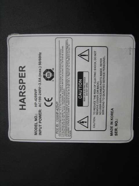
O5XHP-425VP
Nov 27, 2005PDP TV Monitor
Equipment Class
JBP - Part 15 Class B Computing Device Peripheral
O5XHL-420V
Sep 27, 2005LCD Monitor TV
Equipment Class
JBP - Part 15 Class B Computing Device Peripheral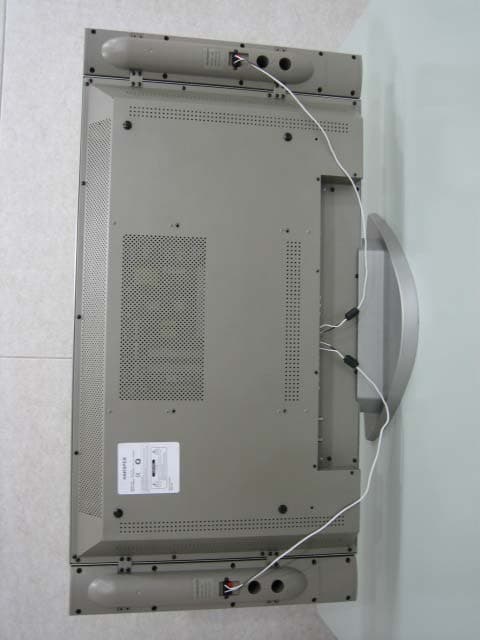
O5XHL-370V
Sep 27, 2005LCD Monitor TV
Equipment Class
JBP - Part 15 Class B Computing Device Peripheral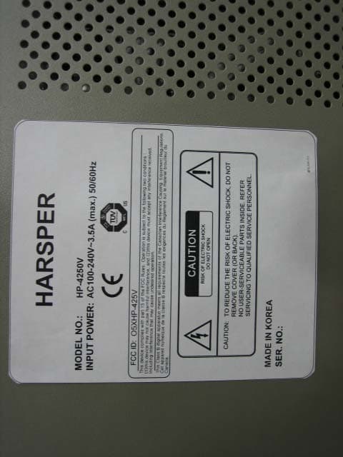
O5XHP-425V
Sep 27, 2005PDP Monitor TV
Equipment Class
JBP - Part 15 Class B Computing Device Peripheral