O6FTBC120Tag reader
Ban-Koe Systems, Inc.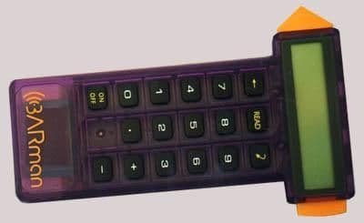
Click to zoom
Application Details
- Equipment Class
- DCD - Part 15 Low Power Transmitter Below 1705 kHz
- Date of Grant
- Feb 20, 2001
- Application Purpose
- Original Equipment
- Date of Application
- Aug 06, 2000
- Equipment Note
- Tag reader
- Frequency Range
- 0.12500000 - 0.12500000
- Company
- Ban-Koe Systems, Inc.
- Country
- United States
Documents & Files
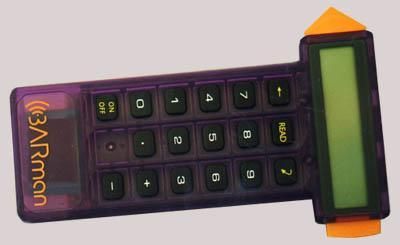
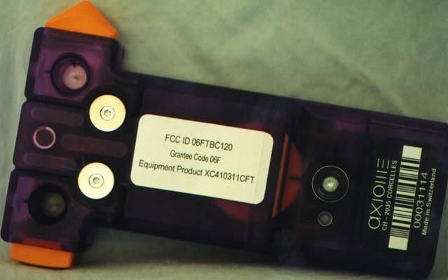
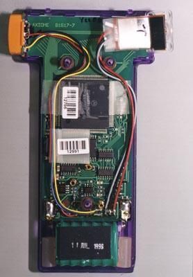

Document Text
Text extracted from the exhibit documents filed with the FCC. Open a document above to read the original.
Users Manual
Copyright© BY AXIOME ALPHA 08/07/00 – all rights reservedUnauthorize d use , duplication or distribution is prohibited.Operating manualManuel d'utilisationBedienerhandbuchVolume 1 ii iii Contents User's Guide .......................................................... 1Guide de l'utilisateur .............................................26Benutzerhandbuch ...............................................49 Appendix, Annexe, Anhang ...................................75 ivWhat you need to use BARman : • at least one BARman , • at least one interface connected to the computer, • a Personal computer, • the AXIOME communication software (MS-DOS or Windows ). 1 BARman T able of contents User's GuideCHAPTER 1 : General description ............................................................................... 4 1.1 - BARman system................................................................................. 4 1.2 - Operating manual ................................................................................. 41.3 - BARman .............................................................................................. 5 1.3.1 - BARman Series 100 : Numeric keypad ................................ 6 1.3.2 - BARman Series 300 : Alphanumeric keypad ....................... 6 1.3.3 - Reading head ............................................................................. 7 1.3.4 - Battery ......................................................................................... 7 1.4 - Interface unit .......................................................................................... 81.5 - BARman 's firmware............................................................................. 8 1.6 - Firmware special functions.................................................................. 9 1.6.1 - BARman 's menu........................................................................ 9 1.6.2 - Message ................................................................................... 101.6.3 - User name................................................................................. 101.6.4 - Time ........................................................................................... 111.6.5 - Date ........................................................................................... 111.6.6 - Memory free space .................................................................. 111.6.7 - BARman status ...................................................................... 11 1.6.8 - Active decoder ......................................................................... 12 1.6.9 - Battery state .............................................................................. 121.6.10 - BARman 's number ................................................................ 12 1.6.11 - Firmware version ................................................................... 131.6.12 - Print ......................................................................................... 13 1.7 - Programming software ...................................................................... 131.8 - MS-DOS communication software ................................................. 14 1.9 - BARman software for Windows95/NT (AxBComm32) ................ 15 1.10 - BARmanager for Windows ............................................................ 15 1.11 - DDEServer for Windows ............................................................... 15 CHAPTER 2 : Maintenance ......................................................................................... 16 2.1 - BARman 's maintenance ................................................................... 16 2.2 - " Left-handed " reading head ............................................................ 16 CHAPTER 3 : Troubleshooting ................................................................................... 18 3.1 - Error messages in BARman ........................................................... 18 CHAPTER 4 : Hard-Reset ........................................................................................... 21 4.1 - BARman -Hard Reset....................................................................... 21 4.2 - Firmware transfer under MS-DOS .................................................. 23 4.3 - Firmware transfer under Windows .................................................. 23 2 User's Guide TRADEMARK INFORMATIONBARman is a registered trademark of AXIOME SA. MS-DOS is a registered trademark of Microsoft Corporation. Macintosh is a registered trademark of Apple Computer, inc. Windows is a registered trademark of Microsoft Corporation. 3 BARman T able of contents 4 User's Guide CHAPTER 1 : General description1.1 - BARman system The BARman is an easy data collecting system composed of: - a portable data entry device with its own clock ( BARman ), - an interface unit (BIU, BEI or CIU),- a communication software for DOS, Windows or Macintosh , - a BARman programming software (AXEL). The BARman is designed to record dated information related to the user's daily activities which will be processed by a computer. The interface units andthe communication software allows to transfer the BARman's data into thecomputer. 1.2 - Operating manual The use of the BARman , it's interfaces and software is explained in several manuals:Volume 1 : This one, is the operating manual which describe the BARman and its firmware. Volume 2 : The interface manual describes the BIU, BEI, CIU, ILS232, ILS 422 et ILM interfaces and their installation. Volume 3 : The user manual describes the communication software AXS for MS-DOS and AxBComm32 for Windows95 . Volume 4 : The BARmanager user's manual describes the BARman programs for Windows . Volume 5 : The programming manual describes the programming of BARman / BARman Laser and the use of the AXEL / AXELE compiler for DOS and Windows95 . Volume 7 : The user ma…
Text truncated - open the document above for the full version.
Block Diagram
All present information is prelimi nary and does not represent any commitment by AXIOME. Technical specifications can change without any prior noticeD:\Ready_To_Convert\Doc\112197.DOC08/03/00 8:31 AM AXIOME OEM TLT-1 Tag Reader Characteristics • Multi-tag reading and writing (EM-Marin, Philips, MicroCID) • Standard frequency of 125 kHz • Very small dimensions • An integrated antenna • Very low power consumption • TTL serial interface Description Thanks to an extremely small volume and power comsumption, the tag reader TLT-1 is ideally suited for OEM integration into hand- held portable readers. The TLT-1 communicates to the terminal via a serial interface. The command set allows reading and writing a large number of different tags in the 125 kHz frequency range. Operating principle The diagram below describes the main elements that compose the TLT-1. When a read or write command is received, the microprocessor generates a chain of basic commands that are sent to the tag via the modulator and antenna. The tag draws energy from the electromagnetic field created by the antenna and returns an information which is then demodulated and formated before being sent on the serial communication line. List of compatible tags The TLT-1 reader is capable of reading and writing the following tag types. TypeMemoryManufacturer Hitag 12 kbit R/WPhilips uCID11061 kbit R/WMicroCID H 4x0264 bit ROElectronic Marin H 4x05128 bit ROElectronic Marin V 40501 kbit R/WElectronic Marin Analog circuit Serial interface Microprocessor ModulatorDemodulator HostAntenna All present information is prelimi nary and does not represent any commitment by AXIOME. Technical specifications can change without any prior noticeD:\Ready_To_Convert\Doc\112197.DOC08/03/00 8:31 AM Command set The TLT-1 tag reader responds to two ASCII characters followed by one or more arguments. The arguments are separated by a comma and represent hexadecimal values. A command line is always terminated by the character "carriage return" ↵ ↵↵ ↵ . Syntax : Command<Argument #1>,<Argument #2>, ... ↵ ↵↵ ↵ Command set • TTTag type • V ?Firmware version • TCTry count • TOTimeout • RDRead • WRWrite • POPolling mode • PIInfinite polling mode • PWSet password • LILogin • WPWrite password After having executed a command, the TLT-1 tag reader returns a reply that begins with an error code which is followed, possibly, by data. The reply is always terminated by the character "carriage return" ↵ ↵↵ ↵ . Syntax : ErrorCode,<Data #1>,<Data #2>, ... ↵ ↵↵ ↵ ErrorCode list • 0OK • 2Unknown command • 3Argument error • 4Execution error • 5Timeout error • 6Transaction error • 7Transaction aborted • 8Login error Example : 0,3142 ↵ ↵↵ ↵ OK and data Electrical Character specifications • Supply voltage5VDC +/- 5% • Current consumption18 mA • Operating frequency125 - 135 kHz • Serial interface • TTL levels (5V) • 9600 bps E,7,1 • RxReceive data • Tx Transmit data • GndGround • VccPower supply • Power On delay80 ms • Reading distance (Tag ∅ 45mm)28 mm Environment • Operating 0 to +70 ° C (32 to 158 °F) • Storage -20 to +70 ° C ( -4 to 158 °F) Mechanical dimensions • Case dimensions23.8 x 15.8 x 10.3 mm • Contacting Pads2.0 x 2.0 mm • Pads pitch2.5 mm 15.8 23. 8 Rx Tx Gnd Vcc 10.3 Approval CE (submitted) ETC 300 (submitted) MicroCID Contact Axiome Alpha SA Rue de la Gare 5a CH-2035 Corcelles Switzerland tel.+41 (0)32 730 46 20 fax+41 (0)32 731 64 93 [email protected] Internet www.axiome.ch
Block Diagram
All present information is prelimi nary and does not represent any commitment by AXIOME. Technical specifications can change without any prior noticeD:\Ready_To_Convert\Doc\112198.DOC08/03/00 8:31 AM AXIOME OEM TLT-1V2 Tag Reader Characteristics • Multi-tag reading and writing (Philips, Telefunken, Sokymat) • Standard frequency of 125 kHz • Very small dimensions • An integrated antenna • Very low power consumption • TTL serial interface Description Thanks to an extremly small volume and power comsumption, the tag reader TLT-1 is ideally suited for OEM integration into hand- held portable readers. The TLT-1 communicates to the terminal via a serial interface. The command set allows reading and writing a large number of different tags in the 125 kHz frequency range. Operating principle The diagram below describes the main elements that compose the TLT-1. When a read or write command is received, the microprocessor generates a chain of basic commands that are sent to the tag via the modulator and antenna. The tag draws energy from the electromagnetic field created by the antenna and returns an information which is then demodulated and formated before being sent on the serial communication line. List of compatible tags The TLT-1 reader is capable of reading and writing the following tag types. TypeMemoryManufacturer HITAG 12 kbit R/WPhilips Temic 5550264 bit R/WTelefunken Temic 5551264 bit R/WTelefunken Temic 5552992 bit R/WTelefunken Nova160 bit R/WSokymat Analog circuit Serial interface Microprocessor ModulatorDemodulator HostAntenna All present information is prelimi nary and does not represent any commitment by AXIOME. Technical specifications can change without any prior noticeD:\Ready_To_Convert\Doc\112198.DOC08/03/00 8:31 AM Command set The TLT-1 tag reader responds to two ASCII characters followed by one or more arguments. The arguments are separated by a comma and represent hexadecimal values. A command line is always terminated by the character "carriage return" ↵ ↵↵ ↵ . Syntax : Command<Argument #1>,<Argument #2>, ... ↵ ↵↵ ↵ Command set • TTTag type • V ?Firmware version • TCTry count • TOTimeout • RDRead • WRWrite • POPolling mode • PIInfinite polling mode • PWSet password • LILogin • WPWrite password After having executed a command, the TLT-1 tag reader returns a reply that begins with an error code which is followed, possibly, by data. The reply is always terminated by the character "carriage return" ↵ ↵↵ ↵ . Syntax : ErrorCode,<Data #1>,<Data #2>, ... ↵ ↵↵ ↵ ErrorCode list • 0OK • 2Unknown command • 3Argument error • 4Execution error • 5Timeout error • 6Transaction error • 7Transaction aborted • 8Login error Example : 0,3142 ↵ ↵↵ ↵ OK and data Electrical Character specifications • Supply voltage5VDC +/- 5% • Current consumption18 mA • Operating frequency125 - 135 kHz • Serial interface • TTL levels (5V) • 9600 bps E,7,1 • RxReceive data • Tx Transmit data • GndGround • VccPower supply • Power On delay80 ms • Reading distance (Tag ∅ 45mm)28 mm Environment • Operating 0 to +70 ° C (32 to 158 °F) • Storage -20 to +70 ° C ( -4 to 158 °F) Mechanical dimensions • Case dimensions23.8 x 15.8 x 10.3 mm • Contacting Pads2.0 x 2.0 mm • Pads pitch2.5 mm 15.8 23. 8 Rx Tx Gnd Vcc 10.3 Approval CE (submitted) ETC 300 (submitted) MicroCID Contact Axiome Alpha SA Rue de la Gare 5a CH-2035 Corcelles Switzerland tel.+41 (0)32 730 46 20 fax+41 (0)32 731 64 93 [email protected] Internet www.axiome.ch
Cover Letter(s)
November 29, 2000 Ms. Katie Hawkins FCC Re: Form 731 Confirmation Number: EA98398 FCC ID: O6FTBC120 Reference #: 16369 Dear Ms. Hawkins: I am writing to formally request more time to finish our application for FCC Certification. The problem has arisen because our testing center initially told us our product does not need certification. It has now been determined that it indeed does require certification. We therefore will get to you as soon as possible the schematics that you asked for, as well as the new testing report. Thank you for your consideration. Sincerely, Gina L. Lombardo Corporate Counsel
Test Report
EMC TEST REPORT COMPANY: ID America/Ban-Koe Companies PRODUCT:TBC-120, Barcode Reader REPORT No:J20019875.011 APPROVED BY:Yuriy Litvinov TEST ENGINEER:Uri Spector DATE: July 14, 2000TOTAL PAGES: 14 All services undertaken are subject to the following general policy: Reports are submitted for exclusive use of the client to whom they are addressed. Their significance is subject to the adequacy and representative character of the samples and to the comprehensiveness of the tests, examinations or surveys made. No quotations from reports or use of Intertek Testing Services name is permitted except as expressly authorized by Intertek Testing Services in writing. The report must not be used by the client to claim product endorsement by NVLAP or any agency of the U.S. Government. The NVLAP logo is applicable for testing to I EC/CISPR 22:1993 and FCC-47 CFR part 15 only. A CONTENTS 1.0JOB DESCRIPTION ..........................................................................................1 2.0TEST SUMMARY ............................................................................................ 2 2.1 Limits for Conducted and Radiated Disturbances .....................................................3 2.2 Emissions Test Results.................................................................................... 3 3.0TEST EQUIPMENT .......................................................................................... 4 4.0TEST CONFIGURATION .................................................................................. 5 4.1 Support Equipment/Services ............................................................................. 5 4.2 Sample Set-Up ............................................................................................. 5 4.3 Mode of Operation ........................................................................................ 5 5.0TEST PROCEDURES .........................................................................................6 5.1 Emissions Testing.......................................................................................... 6 Appendix I - Emissions Test Data .................................................................................... 7 Appendix II - Configuration Photographs ......................................................................... 11 EMC Verification ...................................................................................................... 14 A EMC Report No:J20019875.011 Page 1 of 14 1.0 JOB DESCRIPTION Equipment: TBC-120 Barcode Reader; consisted of the Reader and the Communication Cradle Equipment Serial No: Reader-00026982 Communication Cradle-00057571 Voltage/Phase: 9 VDC via power adapter by Axiome type: FW6199 Customer: Ms. Brenda O’Connell ID America/Ban-Koe Companies 9100 35W South Bloomington, MN 55423 Test Standard:CFR 47:1999, §15.107 and §15.109 Class A Date Sample Submitted :July 14, 2000 Test Work Started :July 14, 2000 Test Work Completed: July 14, 2000 A EMC Report No:J20019875.011 Page 2 of 14 2.0 TEST SUMMARY Referring to the performance criteria and the operating mode during the tests specified in this report, the equipment complies with the requirements according to the following standards. TEST STANDARDTESTCOMMENTS Subpart B – 15.107Conducted EmissionsPass Subpart B – 15.109Radiated EmissionsPass Where comments other than “pass” are entered in the “comments” column, further details may be found in the TEST RESULTS section. A EMC Report No:J20019875.011 Page 3 of 14 2.1Limits for Conducted and Radiated Disturbances for FCC parts 15.107 and 15.109 FREQUENCY OF EMISSION MHz CLASS A (dBμV)CLASS B (dBμV) 0.45 to 1.7056048 1.705 to 307048 NOTE: The lower limit applies at the band edges. FREQUENCY OF EMISSION MHz CLASS A at 10 m (dBμV/m)CLASS B at 3 m (dBμV/m) 30 to 883940 88 to 2164444 216-9604646 Above 9605054 NOTE: In the emission tables above, the tighter limit applies at the band edges. 2.2Emissions Test Results (see Appendix I) No modifications were installed on the unit during the emissions testing. A EMC Report No:J20019875.011 Page 4 of 14 3.0TEST EQUIPMENT Receivers/Spectrum Analyzers DESCRIPTIONSERIAL NO. LAST CAL DATE CAL DUE TICK IF USED HP85462A Receiver RF Section3325A0010605/0005/01X HP85460A RF Filter Section3330A0010905/0005/01X HP85462A Receiver RF Section3549A0030611/9911/00 HP85460A RF Filter Section3448A0027611/9911/00 Antennas DESCRIPTIONSERIAL NO. LAST CAL DATE CAL DUE TICK IF USED Schaffner-Chase Bicono-Log Antenna246809/9909/00 Schaffner-Chase Bicono-Log Antenna263003/0003/01X CDI Biconical Antenna B10061604/0004/01 CDI Biconical Antenna B20061404/0004/01 CDI Biconical Antenna B30061504/0004/01 CDI Biconical Antenna B10063204/0004/01 CDI Biconical Antenna B20062304/0004/01 CDI Biconical Antenna B30060704/0004/01 EMCO Horn Antenna 31159507-451309/9909/00 Artificial Mains Networks/Absorbing Clamps DESCRIPTIONSERIAL NO. LAST CAL DATE CAL DUE TICK IF USED CDI LISN-231611/9911/00X Farnell 1EXLSN930A13603/0003/01 A EMC Report No:J20019875.011 Page 5 of 14 4.0 TEST CONFIGURATION (see Appendix II) 4.1Support Equipment/Services N/A 4.2Sample Set-Up EUT was powered via AC adapter 120 VAC, 60 Hz by Axiome type: FW6199, and was set up as a tabletop unit. During emissions testing the Barcode Reader was attached to the Communication Cradle. Also, RS 232 Communication cable was connected to the Communication Cradle. Cables RS 232 communication cable, shielded, 1.5 meters long, DB9 connector 4.3Mode of Operation Continuous “STANDBY” mode. This setup and mode of operation was found to be the worst case mode to produce the maximum radiated emissions. A EMC Report No:J20019875.011 Page 6 of 14 5.0TEST PROCEDURES 5.1Emissions Testing Radiated emission measurements were performed according to the procedures in ANSI C63.4 (1992). All measurements were performed in Open Area Test Sites. Preliminary scans were performed in the Open Area Test Sites only to determine worst case modes. For eac…
Text truncated - open the document above for the full version.
Test Report
EMC TEST REPORT COMPANY: Ban-Koe Companies (ID America) PRODUCT(S): BARman, AXIOME Test Report No: J20033594.011 APPROVED BY:Yuriy Litvinov TEST ENGINEER:Norman Shpilsher DATE:December 27, 2000TOTAL PAGES: 15 All services undertaken are subject to the following general policy: Reports are submitted for exclusive use of the client to whom they are addressed. Their significance is subject to the adequacy and representative character of the samples and to the comprehensiveness of the tests, examinations or surveys made. This test report and certificate may only be reproduced in its entirety with the written permission of Intertek Testing Services management. The report must not be used by the client to claim product endorsement by NVLAP or any agency of the U.S. Government. The NVLAP logo is applicable for testing to I EC/CISPR 22:1993 and FCC-47 CFR part 15 only. A CONTENTS 1.0JOB DESCRIPTION.............................................................................................................1 2.0TEST SUMMARY................................................................................................................ 2 2.1 FCC 15.209 Radiated Emissions Limits...............................................................................3 2.2 Example of Radiated Emissions Limits Calculation................................................................3 2.3 Emissions Test Results...................................................................................................... 4 3.0TEST EQUIPMENT............................................................................................................. 5 4.0TEST CONFIGURATION.................................................................................................... 6 4.1 Support Equipment/Services.............................................................................................. 6 4.2 Sample Set-Up................................................................................................................. 6 4.3 Mode(s) of Operation........................................................................................................ 6 5.0TEST PROCEDURES............................................................................................................7 5.1 Emissions Testing............................................................................................................. 7 Appendix I - Emissions Test Data...................................................................................................... 8 Appendix II - Configuration Photographs.......................................................................................... 14 A EMC Report No:J20033594.011 Page 1 of 15 1.0 JOB DESCRIPTION Equipment: BARman, AXIOME, CH-2035 CORCELLES Tag Reader Equipment Serial No: 00026982 Voltage/Phase:7.2VDC from internal battery in active mode, or 120VAC/60Hz through FW 6199 120VAC/15VAC Power Adapter and AXIOME Base in charging mode. Customer: Ms. Brenda O’Connell Ban-Koe Companies 9100West Bloomington Freeway Minneapolis, MN 55431 Phone: 952-881-0634, Fax: 952-888-3344 Test Standard:CFR 47:1999, §15.209 Date Sample(s) Submitted:December 8, 2000 Test Work Started:December 15, 2000 Test Work Completed:December 20,2000 A EMC Report No:J20033594.011 Page 2 of 15 2.0 TEST SUMMARY Referring to the performance criteria and the operating mode during the tests specified in this report, the equipment complies with the requirements according to the following standards. TEST STANDARDTESTCOMMENTS Subpart C – 15.209Radiated EmissionsPass Where comments other than “pass” are entered in the “comments” column, further details may be found in the TEST RESULTS section. A EMC Report No:J20033594.011 Page 3 of 15 2.1FCC 15.209 Radiated Emissions Limits FREQUENCY MHz FIELD STRENGTH μV/m MEASURENENT DISTANCE m 0.009 – 0.4902400/F(kHz)300 0.490 – 1.70524000/F(kHz)30 1.705 – 30.03030 30 – 881003 88 – 2161503 216 – 9602003 Above 9605003 NOTE: In the emission tables above, the tighter limit applies at the band edges. 2.2Example of Radiated Emissions Limits Calculation The fundamental output power and harmonic emissions limits are outlined in paragraph 15.209. The fundamental frequency field strength allowed at the distance of 3 meters was calculated to be 105.6 dBμV/m. The second harmonic field strength allowed at the distance of 3 meters was calculated to be 99.6 dBμV/m. The fourth harmonic field strength allowed at the distance of 3 meters was calculated to be 96.0 dBμV/m. Calculation of the field strength of the fundamental frequency: Limit at 300m= 20log (2400/F(kHz)) Limit at 300m= 20log (2400/126.25) Limit at 300m= 20 log (19.01) = 25.6 dBμV/m Limit at 3m= 25.6 dBμV/m + Distance Factor = 25.6 dBμV/m + 80 dB = 105.6 dBμV/m Calculation of the field strength of the second harmonic emissions: Limit at 300m= 20log (2400/F(kHz)) Limit at 300m= 20log (2400/252.5) Limit at 300m= 20 log (9.505) = 19.6 dBμV/m Limit at 3m= 19.6 dBμV/m + Distance Factor = 19.6 dBμV/m + 80 dB = 99.6 dBμV/m Calculation of the field strength of the fourth harmonic emissions: Limit at 30m= 20log (24000/F(kHz)) Limit at 300m= 20log (24000/505) Limit at 300m= 20 log (47.5) = 33.5 dBμV/m Limit at 3m= 19.6 dBμV/m + Distance Factor = 33.5 dBμV/m + 40 dB = 73.5 dBμV/m The limit was extrapolated with Distance Extrapolating Factor. According to FCC 15.31(f)(2) at frequencies below 30MHz the Distance Extrapolating Factor is 40 dB/decade; for measurement distance 3m Distance Factor is 80dB below 0.49 MHz and 40dB above 0.49MHz and below 30MHz. A EMC Report No:J20033594.011 Page 4 of 15 2.3Emissions Test Results (see Appendix I) No modifications were installed on the unit(s) during the emissions testing. Radiated emissions at Fundamental Frequency and Spurious Frequencies comply with FCC 15.209 limits (See Table 1 and Graphs 1, 2, and 3). Fundamental Frequency occupied frequency range from 0.1237 to 0.1288 MHz (See Graph 4). The nearest restricted b…
Text truncated - open the document above for the full version.
Contact Information
Applicant
Gina Lombardo(Corporate Counsel)
Test Firm
Intertek Testing ServicesUri Spector
Technical Specifications
| # | Rule Parts | Frequency Range | Power Output |
|---|---|---|---|
| 1 | 15C | 0.125 MHz - 0.125 MHz | - |