O6KANTHF002Hands Free Kit for Mobile Phone
Ant Telecom Co Ltd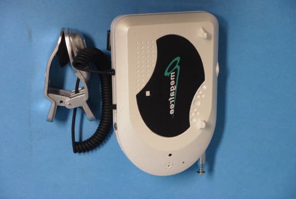
Click to zoom
Application Details
- Equipment Class
- DXX - Part 15 Low Power Communication Device Transmitter
- Date of Grant
- Dec 07, 2001
- Application Purpose
- Original Equipment
- Date of Application
- Dec 07, 2001
- Equipment Note
- Hands Free Kit for Mobile Phone
- Frequency Range
- 88.30000000 - 88.30000000
- Company
- Ant Telecom Co Ltd
- Country
- South Korea
Documents & Files
Document Text
Text extracted from the exhibit documents filed with the FCC. Open a document above to read the original.
Users Manual
Ant Telecom co., ltd Cheongwun B/D 6F, 990-198, Keomsa-dong Dong-gu, Daegu, Korea (701-040) Tel>82.53.985.2500 Fax>82.53.985.3119 www.ant21c.com Product Introduction This product allows a person listen to the other party’s voice through the FM Radio increasing the safety of the driver who is using the mobile phone while he/she is driving. The product is a new concept and new sense of wireless hands free. This product was designed for safety and convenient use of a cellular phone in a vehicle, an office or any other place at any time. 1. Wireless Hands Free Function 2. Amplified high-quality sound through your car audio 3. Auto power ON/OFF Function 4. Privacy Communication Function 5. Easy to install and operate 6. Built in microphone 7. 3 Different volume control level for clearer sound to the receiver 8. Built in magnet phone holder 9. Protect from EMI phone radiation ù Privacy conversation 1. Connect the earphone jack into the MEGA FREEunit. 2. Either turn your radio off, lower the volume, or change the station ù Receiver's volume control Select one of three positions until person you are speaking to tells you your sound is the clearest. ù Auto power ON/OFF function : When you attach the cellular phone to the MEGA FREE, it operate automatically. 1. Frequency : 88.3MHz ± 0.1 2. Size : 110 × 15 × 60 ( H × T × W ) 3. Weight : 78 g 4. Input Voltage : DC 3V ( AAA Battery × 2 ) 5. Battery Life(Using time) : about 300 hours 6. MIC. Sensitivity : 42 dB ± 4 dB STEP 1 1. Insert battery into MEGA FREE. 2. Install MEGA FREE at your car's sun-visor. STEP 2 3. Take up the pincers of your phone speaker. STEP 3 4. Peel off the paper from double-sided tape at the back of the metal sticker. 5. Stick the metal sticker firmly to the center of the battery at the back of the cellular phone. STEP 4 6. Attach the cellular phone to the MEGA FREE. 7. Set your FM frequency to 88.3MHz in your car audio. STEP 1 1. Select preset FM channel. STEP 2 2. Make phone call as you normally do. STEP 3 3. Enjoy the convenience of driving hands free while you talk. STEP 4 4. Turn off the phone after conversation. - Receiving a call 1. Select preset FM channel. 2. Press send button on your cellular unit to receive phone call. 3. Make handset and radio volume adjustments as in “Making a call” above. 4. Turn off the phone after conversation. Federal Communication Interference Statement Pursuant to past 15 of the FCC Rules These limits are designed to provide reasonable protection against harmful interference in a residential installation. This equipment generates, uses and can radio frequency energy and, if not installed and used in accordance with the instructions, may cause harmful interference to radio communications. However, there is no guarantee that interference will not occur in a particular installation. If this equipment does cause harmful interference to radio or television reception, which can be determined by turning the equipment off and on, the user is encouraged to try to correct the interference by one of the following measures; - Reorient or relocate the receiving antenna. - Increase the separation between the equipment and receiver. - Connect the equipment into an outlet on a circuit different from that to which the receiver is connected. - Consult the dealer or an experienced radio TV technician for help. FCC Caution : Any changes or modifications not expressly approved by the party responsible for compliance could void the user’s authority to operate this equipment.
Block Diagram
Cheongwun B/D 6F, 990-198, Keomsa-Dong, Dong-Gu, Daegu, Korea TEL) 053-985-2500 FAX) 053-985-3119 E-MAIL) [email protected] BLOCK DIAGRAM 1. MIC AMP Amplify a voice signal and transmit it to the RF amplifier 2. RF AMP1 / RF AMP2 / RF-OSC Transmit the signals for Mic Amp and Voice Amp to a radio cassette by the medium of FM 88.3 MHz. 3. VOICE AMP Amplify the voice signal of caller and transmit it to the RF amplifier 4. ECHO CANCELER A echo phenomenon is canceling while talking over the telephone. 5. VOLTAGE REGULATOR Convert 12~24 voltage into 5 voltage. MIC AMP U3B VOLTAGE REGULATOR U1 ECHO CANCELER U2B, Q4 VOICE AMP U2A RF-OSC Q3 RF AMP1 Q1 RF AMP2 Q2 MIC CONNECTOR WITH H/P ANTENNA 88.3MHz
Cover Letter(s)
Question #1: Please provide test setup photos. Question #2: Please provide the instrument setting in making Average measurement for fundamental frequency. ===> (Q1,Q2) : I attach the test setup photos include fully extended antenna and average detect mode picture Question #3: In accordance with 15.35, when average detector is used to demonstrate compliance, the provision in 15.35 for limiting peak emission also apply. Please provide the peak reading for fundamental emission. Question #4: Please provide specturm plot to demonstrate 15.239 ( a) compliance. ===> (Q3,Q4) : peak value evaluation is described in test report page 9. Question #5: This device is equipped with audio connector. In accordance with ANSI C63.4 section 13.1.1.1, " if a device is equipped with input connectors for external modulation, typical modulating signals shall be applied at the max. rated input level for the device when modulation is required for individual tests. There is no information provided in your test procedure to indicate that such external modulation was applied to the device. Please redo the radiated emission test by appliing external audio modulation at the max. rate. ===> Q5 : There is no input connector. Please find more information in test report page 6 'Test Setup Description'. In this case, is it need to adjust maximum input condition ? Question #6: The information to user as indicated in the last page of user manual does not apply to this device. There is no Class B limits for intentional transmitter. Please provide revised user manual. ===> Q6 : I attached modified user manual. Question #7: Since there is no setup photos to show the test conditions, please make sure the radiated emission tests were done with the antenna fully extended. ===> Q7 : same with comment of Q1, Q2 Sincerely yours. H.C.Kim/EMC Engnieer > Question #8 : What is the connector which is above the volume adjustment ? ==> See the test setup description of page 6 of the test report. > Question #9: The instrument setting for peak measurement reported in page 9 > of test report is not correct. For frequency range from 30 MH - 1000MHz > shall use RBW/VBW=100kHz. Please take a look ANSI C63.4 Section 4.2. > Please provide peak measurement with RBW=100kHz and VBW=100kHz. ==> I revised the test report with two detect mode of peak and average according your notice. Please refer to page 8. > Question #10: In my previous question #2, I am asking the instrument setting > with Average detector. Please provide the Resolution Bandwidth (RBW) and > Vidoe bandwidth ( VBW) used during Average measurements. ==> I used the bandwidth 100kHz for this test. It was described in the test report. > Question #11: If there is audio connector, you will need to redo radiated > emission test in accordance with my question #5. ==> I understnad what you mean. I have no information for the connector type product from manufacture. > Question #12: In the revised user manual, you did not include the > requirement per 15.21 requirement. Please include 15.21 statement in the > user manual and provided the revised user manual again. ==> I have uploaded the user manual again.
External Photos
IST Co., Ltd. EMC LABORATORY DUT Photos-External Megafree / Ref. TEST REPORT NO. : 01-IST-169 1 of 1
ID Label/Location Info
IST Co., Ltd. EMC LABORATORY DUT Label Sample & Location Megafree / Ref. TEST REPORT NO. : 01-IST-169 1 of 1 FCC ID : O6KANTHF002
Internal Photos
IST Co., Ltd. EMC LABORATORY DUT Photos-Internal Megafree / Ref. TEST REPORT NO. : 01-IST-169 1 of 1 IST Co., Ltd. EMC LABORATORY DUT Photos-Internal Megafree / Ref. TEST REPORT NO. : 01-IST-169 2 of 2
Operational Description
Ant Telecom co., ltd Cheongwun B/D 6F, 990-198, Keomsa-dong Dong-gu, Daegu, Korea (701-040) Tel>82.53.985.2500 Fax>82.53.985.3119 www.ant21c.com Operational Description 1. MIC AMP Amplify a voice signal and transmit it to the RF amplifier 2. RF AMP1 / RF AMP2 / RF-OSC Transmit the signals for MIC. Amp and Voice Amp to a car radio by the medium of FM 88.3 MHz. 3. VOICE AMP Amplify the voice signal of caller and transmit it to the RF amplifier 4. ECHO CANCELER A echo phenomenon is canceling while talking over the telephone. 5. BATTERY – 3V The battery of 3voltage is a power supplier.
Test Report
IST Co., Ltd. EMC LABORATORY TEST REPORT NO. : 01-IST-169 1 of 9 Certification of Compliance CFR 47 Part 15 Subpart C Test Report File No. : 01-IST-169 Date of Issue : Dec 7, 2001 Model(s) : Megafree Kind of Product : Hands Free Kit Applicant : Ant Telecom Co., Ltd. Address : Cheongwun B/D 6F, 990-198, Keomsa-dong, Dong-gu, Daegu, 701-040 , Korea Manufacturer : Ant Telecom Co., Ltd. Address : Cheongwun B/D 6F, 990-198, Keomsa-dong, Dong-gu, Daegu, 701-040 , Korea Test Result Positive Negative Reviewed By Approved By J.H. Lee / General Manager of EMC G. Chung / Chief - The test report with appendix consists of 9 pages. - The test result only responds to the tested sample. - It is not allowed to copy this report even partly without the allowance of IST EMC Laboratory. - This equipment as for has been shown to be capable of continued compliance with the applicable technical standards as indicated in the measurement report and was tested in accordance with the measurement procedures specified in ANSI C63.4 1992. IST Co., Ltd. EMC LABORATORY TEST REPORT NO. : 01-IST-169 2 of 9 TABLE OF CONTENTS Table of contents 2 Information of test laboratory, Environmental condition, Power used 3 Description of test Conducted Emission 4 Radiated Emission 5 Test Setup Description 6 Summary 6 Test conditions and data Radiated emissions 30 MHz – 1 GHz Applicable Test equipment 7 Data and plots 8-9 Appendix IST Co., Ltd. EMC LABORATORY TEST REPORT NO. : 01-IST-169 3 of 9 INFORMATIONS OF TEST LABORATORY EMC LABORATORY of IST Co., Ltd. San 21-8, Goan-Ri, Baekam-Myun, Yongin-City Kyonggi-Do, 449-860, Korea TEL : +82 31 333 4093 FAX : +82 31 333 4094 ENVIRONMENTAL CONDITIONS Temperature 12 degree Humidity 43 percent Atmospheric pressure 1002 mbar POWER SUPPLY SYSTEM USED Power supply system DC 3V ( AAA Battery x 2 ) IST Co., Ltd. EMC LABORATORY TEST REPORT NO. : 01-IST-169 4 of 9 DESCRIPTIONS OF TEST Conducted Emissions: The measurement were performed over the frequency range of 0.45MHz to 30MHz using a 50/50uH LISN as the input transducer to a Spectrum Analyzer or a Field Intensity Meter. The measurements were made with the detector set for "Peak" amplitude within a bandwidth of 10KHz or for "quasi-peak" within a bandwidth of 9KHz. - Procedure of Test The line-conducted facility is located inside a shielded room No.1. A 1m X 1.5m wooden table 80cm height is placed 40cm away from the vertical wall and 1.5m away from the other wall of the shielded room. The R/S ESH3-Z5 and EMCO 3825/2 LISN are bonded to bottom of the shielded room. The EUT is located on the wooden table with distance more than 80cm from the LISN and powered from the EMCO LISN .The peripheral equipment is powered from the other LISN. Power to the LISNs are filtered by a noise cut power line filters. All electrical cables are shielded by braided tinned steel tubing with inner φ 1.2cm. If the EUT is a DC-powered device, power will be derived from the source power supply it normally will be powered from and this supply lines will be connected to the EMCO LISN. All interconnecting cables more than 1m were shortened by non- inductive bundling to a 1m length. Sufficient time for the EUT, support equipment, and test equipment was allowed in order for them to warm up to their normal operating conditions. The RF output of the LISN was connected to the R/S receiver to determine the frequency producing the maximum emission from the EUT. The frequency producing the maximum level was reexamined using Quasi-Peak mode by manual measurement, after scanned by automatic Peak mode for frequency range from 0.45 to 30MHz. The bandwidth of the receiver was set to 10kHz. The EUT, peripheral equipment, and interconnecting cables were arranged and manipulated to maximize each EME emission. 215 >150>40 80 Receiver EUT LISN 80 ≥ 80 80 40 ≥ 80 Measuring apparatus Mains Filter Mains Front side Equipment under test Coaxial cable Artificial mains network Screened room Non-metallic support 80 IST Co., Ltd. EMC LABORATORY TEST REPORT NO. : 01-IST-169 5 of 9 DESCRIPTION OF TEST Radiated Emissions: The measurement was performed over the frequency range of 30MHz to 1GHz using antenna as the input transducer to a Spectrum analyzer or a Field Intensity Meter. The measurement was made with the detector set for the peak or the average detect mode with RBW of 1MHz for chamber and IF BW of 100kHz for OATS. - Procedure of Test Preliminary measurements were made at 3 meter using bi-conical and log-periodic antennas, and spectrum analyzer to determine the frequency producing the max. emission in anechoic chamber. Appropriate precaution was taken to ensure that all emission from the EUT were maximized and investigated. The system configuration, mode of operation, turn-table azimuth and height with respect to the antenna were noted for each frequency found. The spectrum was scanned from 30MHz to 300MHz using S/B bi-conical antenna and 300 to 1000MHz using S/B log-periodic antenna. Above 1GHz, linearly polarized double ridge horn antennas were used. Final measurements were made at open site with 3-meters test distance using S/B bi-log antenna or horn antenna. The OATS have been verified in regular for its normalized site attenuation. The test equipment was placed on a wooden table. Sufficient time for the EUT, peripheral equipment, and test equipment was allowed in order for them to warm up to their normal operating condition. Each frequency found during pre-scan measurements was re-examined by manual. The detector function was set to the peak and the average mode with the bandwidth of the receiver was set to 100kHz depending on the frequency of type of signal. Sometimes the average detect function cab be used for its appropriate measurement. The EUT, peripheral equipment and interconnecting cables were re-configured to the set-up producing the max. emission for the frequency and were placed on top of a 0.8- meter high nonmetallic 1 x 1.5 meter table. The EUT, peripheral equipment, and interconne…
Text truncated - open the document above for the full version.
Test Setup Photos
IST Co., Ltd. EMC LABORATORY Test Setup Photos-Megafree / Ref. TEST REPORT NO. : 01-IST-169 1 of 1 Radiated Emissions (fully extended antenna) Average detect Peak detect Quasi-peak detect MIL detect Select Button
Contact Information
Applicant
Eun-Kuk Lee(President)
Test Firm
IST Co., LtdBong Kyoon Bae
Technical Specifications
| # | Rule Parts | Frequency Range | Power Output |
|---|---|---|---|
| 1 | 15C | 88.3 MHz - 88.3 MHz | - |
Other Applications from Ant Telecom Co Ltd
O6KANTHF001
Oct 04, 2000Wireless Hands Free Kit
Equipment Class
DXX - Part 15 Low Power Communication Device Transmitter