O6O-037-0TBM18Wireless Video Camera
Falcon Machine Tools Co Ltd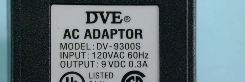
Click to zoom
Application Details
- Equipment Class
- DXX - Part 15 Low Power Communication Device Transmitter
- Date of Grant
- Nov 17, 2003
- Application Purpose
- Original Equipment
- Date of Application
- Nov 17, 2003
- Equipment Note
- Wireless Video Camera
- Frequency Range
- 2410.00000000 - 2470.00000000
- Company
- Falcon Machine Tools Co Ltd
- Country
- Taiwan
Documents & Files
Document Text
Text extracted from the exhibit documents filed with the FCC. Open a document above to read the original.
Users Manual
2.4 GHz WIRELESS SURVEILLANCE SYSTEM Operating Instructions Te s t e d C o m p l y Wit h FCC Standar ds Model # TBM-18 BEFORE OPERATING THIS PRODUCT, READ, UNDERSTAND, AND FOLLOW THESE INSTRUCTIONS. Be sure to save this booklet for future reference. 1 IMPORTANT SAFETY INSTRUCTIONS WARNING: TO AVOID THE RISK OF ELECTRICAL SHOCK, ALWAYS MAKE SURE THE PRODUCT IS UNPLUGGED FROM THE ELECTRICAL OUTLET BEFORE RELOCATING, SERVICING, OR CLEANING IT. • This product is intended for non-commercial, household use in providing video surveillance. • This product is not a toy. • Do not use the product for any other purpose. • Keep the product out of the reach of children and pets. Children do not intend this product for use. • Do not leave the product unattended while it is in use. Always unplug the product from the electrical outlet when it is not in use. • Keep the product away from direct sunlight, open flame or other heat sources, humidity or dusty environments. • Do not block any ventilation openings. Install the product in accordance with the operating instructions. • Do not use attachments not recommended or sold by the product manufacturer, as a risk of fire, electrical shock, or serious personal injury may result. • Unplug the product from the electrical outlet prior to putting on or removing parts. • Plug the product into a standard 120V AC electrical outlet. • Do not use this product with a voltage converter. • Do not plug or unplug the product from the electrical outlet with a wet hand, as a risk of electrical shock exists. • Disconnect the plug (do not pull on the Power Cord) from the electrical outlet. • Do not allow the Power Cord to hang (i.e., over the edge of a table or counter) where it may be tripped over or pulled. • Protect the power cord from being walked on or pinched, particularly at plugs, convenience receptacles, and the point where they exit the product. • If using an extension cord, the marked electrical rating of the cord set or extension cord should be at least as great as the electrical rating of the product. • Never operate this product if it has a damaged Power Cord or plug, malfunctions or is not working properly, has been dropped, or damaged. This product has no user-serviceable parts. Do not attempt to examine or repair this product yourself. Only qualified service personnel should perform any servicing. • This product is intended for personal, non-commercial, non-industrial, household use only. Do not use outdoors. 2 General Description: The wireless, Bear Video Camera (Model #TBM-18) transmits video and audio signals at a frequency of 2.4 GHz to the video signal receiver (Model #VSB8RX). The video signal receiver outputs these signals via cable to your TV/VCR for monitoring and/or recording. Equipment & accessories: 1. 1 x Bear Video Camera (Model # TBM-18) 2. 1 x Receiver (Model #VSB8RX) 3. 1 x Audio/Video Cable 4. 2 x AC Power Adaptor (DC 9V) Bear Camera real eye (right eye) DC-9V Power ON /OFF Channel Switch DC-9V 9V Battery (This part is option for user) Battery room and SW Board AC Power Adaptor 3 Installation: Bear Video Camera (Model #TBM-18) 1. Power by either the Battery and DC power of the Bear video camera. 2. Position the video camera in the desired location. NOTE: The transmission range of the Bear video camera at open side up to 150 ft. Real distance is depends on its operating environment. If you are receiving poor video images from the camera, try shortening the transmission range. Reposition and/or adjust the Bear video camera if video transmission is being degraded by obstructions in its operating environment. 3. Select the desired transmission channel for the Bear video camera. NOTE: The Model #TBM-18 Bear video camera has four (4) different transmission channels. The Bear video camera has been set to transmit on CH 1 at the factory. Do not set and/or use more than one (1) video camera on the same transmission channel in order to prevent signal interference and unclear picture reception. a. Remove the Channel Switch rubber grommet from the Bear video camera (front) base. (Refer to the diagram in the “Equipment and accessories” section.) b. Use a small, blunted, pointed object to slide Channel Switch inside of the base opening, as desired (Channel 1-4). c. Securely reattach the Channel Switch rubber grommet onto the video camera base. NOTE: Reference the “Receiver (Model #VSB8RX)” section to update the receiver channel selection. 4. Open the Bear Camera Battery Zip put 9V battery in the battery room or connects the AC Power Adaptor Jack end to the DC Input Jack end of the Bear Video camera. 5. Plug the AC Power Adaptor into a standard 120V AC electrical outlet. 6. Unplug the AC Power Adaptor from the electrical outlet when it is not in use or is left unattended. 7. When DV9V Plug in Jack the Battery power will Auto switch off. 8. Please use 9V ALKALINE Battery for battery source Receiver (Model #VSB8RX): CAUTION: Make all of the necessary wire jack connections before plugging the AC Power Adaptor into an electrical outlet, as a risk of electrical shock may exist. Keep away from water, fire raindrop and high humidity 1. Insert the 3.5Ø cable plug into the A/V Output Jack of the receiver. 2. Insert the (yellow & white) cable plugs into the Video Input and Audio Input Jacks of your TV, as appropriate. 4 2.4GHz Receiver (VSB8RX) Yellow Plug Video /Video Cable TV Video Input Jack 3.5 Plug Audio Input Jack White Plug 2. Connect the AC Power Adaptor Jack end to the 9V DC Power Input Jack of the receiver. 3. Select/match the receiver channel to the desired video camera transmission channel. 4. Plug the AC Power Adaptor into a standard 120V AC electrical outlet. 5. Slide the ON/OFF Switch to the ON position. 6. Television Set configuration: a. Turn on the power to the television set (TV). b. Switch the TV channel to the VIDEO/LINE INPUT position. c. Adjust the TV volume and picture, as desired. 7. Unplug the AC Power Adaptor from the electrical outlet when…
Text truncated - open the document above for the full version.
Cover Letter(s)
American Telecommunications Certification Body Inc. 6731 Whittier Ave, McLean, VA 22101 November 6, 2003 RE: FCC ID: O6O-037-0TBM18 Attention: Vivi Wang / Ellis Wu I have a few comments on this Application. 1. Please note that the block diagram for part 15 intentional radiators must provide information on the clocks and their paths of the intentional radiator. Please note that the block diagram provided is a system block and not a block diagram of the intentional radiator portion of the device. Please provide a block diagram of the rf transmitter portion of this device. 2. Please note that the manual states transmission of the video signal is up to 150 feet. Please note that this does not seem to be a realistic transmission distance for a 15.249 devices. Please explain how this device operates at this stated distance (e.g. receiver sensitivity requirements etc) 3. Please note that there is apparently more than sufficient room on the label or device to accommodate the required 2 condition statement in 15.19. Please provide a sample of this 2 condition statement on the device. Alternately, please explain how this device meets the exclusions of 15.19(a)(5). 4. Please note that a number of radiated emissions readings are shown as having ‘raw’ readings at or below 0dBuV/m. Correction factors are then added. Since there does not appear to be preamplifier factors involved, this potentially puts the readings below or in the area that may be adversely affected by the dynamic range of the analyzer (below noise levels). For this reason it is generally prudent to use a preamplifier in line with the antenna and to use a notch filter to filter out the fundamental. when measuring spurious emissions. The fundamental is then measured separately without the notch filter. This is especially problematic on the restricted band 4820MHz reading shown on page 39 of the report. Due to the extremely low raw reading (16dB), no preamplifier used and the fact that this frequency is only -0.1dB from the restricted band limit, please explain what efforts were taken in the spurious emissions measurement process to make sure that this reading on the analyzer was accurate and is not actually failing. 5. Please explain if this device was tested in all three axis (orthogonal planes). Dennis Ward mailto:[email protected] The items indicated above must be submitted before processing can continue on the above referenced application. Failure to provide the requested information may result in application termination. Correspondence should be considered part of the permanent submission and may be viewed from the Internet after a Grant of Equipment Authorization is issued. Please do not respond to this correspondence using the email reply button. In order for your response to be processed expeditiously, you must submit your documents through the AmericanTCB.com website. Also, please note that partial responses increase processing time and should not be submitted. Any questions about the content of this correspondence should be directed to the sender.
Cover Letter(s)
Dennis, I would reply you the below command. Our explanation for the minus raw data as following: 1. For spurious emissions below 1000MHz, normaly the emission signal was monitored by the spectrum with pre-amp., and make sure signal at the Max. value then switch the signal to test receiver. One 10dB pre-amp. was builded in the test receiver, if the signal is near to the backgruond signal, it is possiblel that the test value lower than 0dB. 2. For spurious emissions above 1000MHz, the Agilent pre-amp. was used for measuremnet besides highpass filter. The amplifier factor is kept in the test software, when the test value of spectrum analyzer wrote to test software, raw data automatically reduced the Pre-amp. factor from reading value of spectrum analyzer, so the raw data is minus if the reading value of spectrum analyzer is quite low. Any further question please let us know it. HI Stephanie Please respond to item 4. What steps were taken to insure that the extremely low readings taken are accurate. This is important since the limit is only 0.1dB in the restricted band. Without the use of a preamp or other techniques to verify such low readings the margin is in question. Please respond by explaining how you insured/verified compliance of this device in the restricted band without the use of a preamp to increase the low signal to a measurably accurate level. Thanks Dennis
Cover Letter(s)
Dear Dennis: There you are. And I asked the engineer, they told me that they test in three axis. They found that X axis is the worst case. So they gave us the raw data to put on the report. Thank you for your kind assistance. Best Regards, Stephanie Hung (洪榭薇) Advance Data Technology Corporation (誠信科技) Website: www.adt.com.tw Tel: 886-3 327 0910 Ext. 1668 Fax: 886-3 327 0892 e-mail: [email protected]
External Photos
Page 1 CONSTRUCTION PHOTOS OF EUT (For Model: TBM-18 ) Page 2 Page 3 (For Model: TJM-275) Page 4 Page 5 Page 6 Page 7 Page 8 Page 9 (For Model: TCM-30) Page 10 Page 11
ID Label/Location Info
Page 1 (For Model: TBM-18 ) (For Model: TJM-275) Label Location Label Location Page 2 (For Model: TCM-30) Label Location
Internal Photos
Page 1 CONSTRUCTION PHOTOS OF EUT (For Model: TBM-18 ) Page 2 Page 3 Page 4 Page 5 Page 6 Page 7 Page 8 Page 9 Page 10 Page 11 (For Model: TJM-275) Page 12 Page 13 Page 14 Page 15 Page 16 Page 17 Page 18 Page 19 Page 20 (For Model: TCM-30) Page 21 Page 22 Page 23 Page 24 Page 25 Page 26 Page 27 Page 28
Operational Description
FCC ID: O6O-037-0TBM18 ADT No.920712R03 Operational Description The EUT (Wireless Video Camera), the Transmitter is 2.4GHz. The EUT is powered by AC power adapter and uses Printed antenna. There are four channels in this product and channel selection is controlled by switch in 2.4GHz transmitter.
Test Report
FCC ID: O6O-037-0TBM18 Report No.: RF920712R031Issued: Oct. 02, 2003 FCC TEST REPORT REPORT NO.: RF920712R03 MODEL NO.: TBM-18, TCM-30, TJM-275 RECEIVED: July 12, 2003 TESTED: Sept. 03 ~ Sept. 30, 2003 APPLICANT: Falcom Machine Tools Co., Ltd ADDRESS: No. 264, Shing Kong Rad, He Mei, Chang Hua, Taiwan, 508 R.O.C. ISSUED BY: Advance Data Technology Corporation LAB LOCATION: 47 14th Lin, Chiapau Tsun, Linko, Taipei, Taiwan, R.O.C. This test report consists of 55 pages in total. It may be duplicated completely for legal use with the approval of the applicant. It should not be reproduced except in full, without the written approval of our laboratory. The client should not use it to claim product endorsement by CNLA, NVLAP or any government agencies. The test results in the report only apply to the tested sample. 0528 ILAC MRA Lab Code: 200102-0 FCC ID: O6O-037-0TBM18 Report No.: RF920712R032Issued: Oct. 02, 2003 Table of Contents 1CERTIFICATION......................................................................................3 2SUMMARY OF TEST RESULTS .............................................................4 3.GENERAL INFORMATION ......................................................................5 3.1GENERAL DESCRIPTION OF EUT ........................................................5 3.2DESCRIPTION OF TEST MODES ..........................................................6 3.3GENERAL DESCRIPTION OF APPLIED STANDARDS..........................6 3.4DESCRIPTION OF SUPPORT UNITS ....................................................7 3.5CONFIGURATION OF SYSTEM UNDER TEST.....................................7 4.TEST TYPES AND RESULTS .................................................................8 4.1CONDUCTED EMISSION MEASUREMENT...........................................8 4.1.1LIMITS OF CONDUCTED EMISSION MEASUREMENT ........................8 4.1.2TEST INSTRUMENTS.............................................................................8 4.1.3TEST PROCEDURES .............................................................................9 4.1.4DEVIATION FROM TEST STANDARD....................................................9 4.1.5TEST SETUP.........................................................................................10 4.1.6EUT OPERATING CONDITIONS ..........................................................10 4.1.7TEST RESULTS (A)............................................................................... 11 4.1.8TEST RESULTS (B)...............................................................................17 4.1.9TEST RESULTS (C) ..............................................................................23 4.2RADIATED EMISSION MEASUREMENT..............................................29 4.2.1LIMITS OF RADIATED EMISSION MEASUREMENT ...........................29 4.2.2TEST INSTRUMENTS...........................................................................30 4.2.3TEST PROCEDURES ...........................................................................31 4.2.4DEVIATION FROM TEST STANDARD..................................................31 4.2.5TEST SETUP.........................................................................................32 4.2.6EUT OPERATING CONDITIONS ..........................................................32 4.2.7TEST RESULTS (A)...............................................................................33 4.2.8TEST RESULTS (B)...............................................................................38 4.2.9TEST RESULTS (C) ..............................................................................42 4.3BAND EDGES MEASUREMENT ..........................................................46 4.3.1LIMITS OF BAND EDGES MEASUREMENT ........................................46 4.3.2TEST INSTRUMENTS...........................................................................46 4.3.3TEST PROCEDURE..............................................................................46 4.3.4EUT OPERATING CONDITION.............................................................46 4.3.5TEST RESULTS ....................................................................................46 5.PHOTOGRAPHS OF THE TEST CONFIGURATION ............................49 6.INFORMATION ON THE TESTING LABORATORIES...........................55 FCC ID: O6O-037-0TBM18 Report No.: RF920712R033Issued: Oct. 02, 2003 1 CERTIFICATION PRODUCT : Wireless Video Camera MODEL NO.: TBM-18, TCM-30, TJM-275 BRAND: CHEVALIER APPLICANT : Falcom Machine Tools Co., Ltd TEST ITEM: ENGINEERING SAMPLE STANDARDS : 47 CFR Part 15, Subpart C (Section 15.249), ANSI C63.4-1992 We, Advance Data Technology Corporation, hereby certify that four samples of the designation have been tested in our facility from Sept. 03 to Sept. 30, 2003. The test record, data evaluation and Equipment Under Test (EUT) configurations represented herein are true and accurate accounts of the measurements of the sample's EMC characteristics under the conditions herein specified. FCC ID: O6O-037-0TBM18 Report No.: RF920712R034Issued: Oct. 02, 2003 2 SUMMARY OF TEST RESULTS The EUT has been tested according to the following specifications: APPLIED STANDARD: 47 CFR Part 15, Subpart C STANDARD PARAGRAPH TEST TYPERESULTREMARK 15.207Conducted Emission TestPASS Minimum passing margin is -22.38dB at 0.505MHz 15.209 15.249 Radiated Emission TestPASS Minimum passing margin is –0.10dB at 4820.00MHz 15.249 Band Edge Measurement Limit: 20 dB less than the peak value of fundamental frequency PASS Meet the requirement of limit NOTE1: The receiver part to communicate with the EUT has been verified to comply with FCC Part 15, Subpart B, Class B (DoC). The test report can be provided upon request. NOTE2: The information of measurement uncertainty is available upon the customer’s request. FCC ID: O6O-037-0TBM18 Report No.: RF920712R035Issued: Oct. 02, 2003 3. GENERAL INFORMATION 3.1 GENERAL DESCRIPTION OF EUT PRODUCT Wireless Video Camera MODEL NO. TBM-18, TC…
Text truncated - open the document above for the full version.
Test Setup Photos
FCC ID: O6O-037-0TBM18 Report No.: RF920712R0349Issued: Oct. 02, 2003 5. PHOTOGRAPHS OF THE TEST CONFIGURATION CONDUCTED EMISSION TEST (For model: TBM-18) FCC ID: O6O-037-0TBM18 Report No.: RF920712R0350Issued: Oct. 02, 2003 (For model: TCM-30) FCC ID: O6O-037-0TBM18 Report No.: RF920712R0351Issued: Oct. 02, 2003 (For model: TJM-275) FCC ID: O6O-037-0TBM18 Report No.: RF920712R0352Issued: Oct. 02, 2003 RADIATED EMISSION TEST (For model: TBM-18) FCC ID: O6O-037-0TBM18 Report No.: RF920712R0353Issued: Oct. 02, 2003 (For model: TCM-30) FCC ID: O6O-037-0TBM18 Report No.: RF920712R0354Issued: Oct. 02, 2003 (For model: TJM-275)
Contact Information
Applicant
David Chen(Senior Manager)
Technical Contact
Advance Data Technology CorporationVivi Wang
886-3-327-0910
13-1, Lane19, WenShan 3rd ., St., · Taoyuan · Taiwan
Test Firm
Bureau Veritas CPS (H.K.) Ltd. Taoyuan BranchRichard Chen
Technical Specifications
| # | Rule Parts | Frequency Range | Power Output |
|---|---|---|---|
| 1 | 15C | 2.41 GHz - 2.47 GHz | - |
Other Applications from Falcon Machine Tools Co Ltd

O6O-012-00MVW9
Feb 22, 2001Wireless Video Camera
Equipment Class
DXX - Part 15 Low Power Communication Device Transmitter
O6O-008-00VOC9
Nov 15, 20002.4GHz Wireless Video Camera
Equipment Class
DXX - Part 15 Low Power Communication Device Transmitter