O7P-362802.11 TYPE WIFI MODULE
Inventek Systems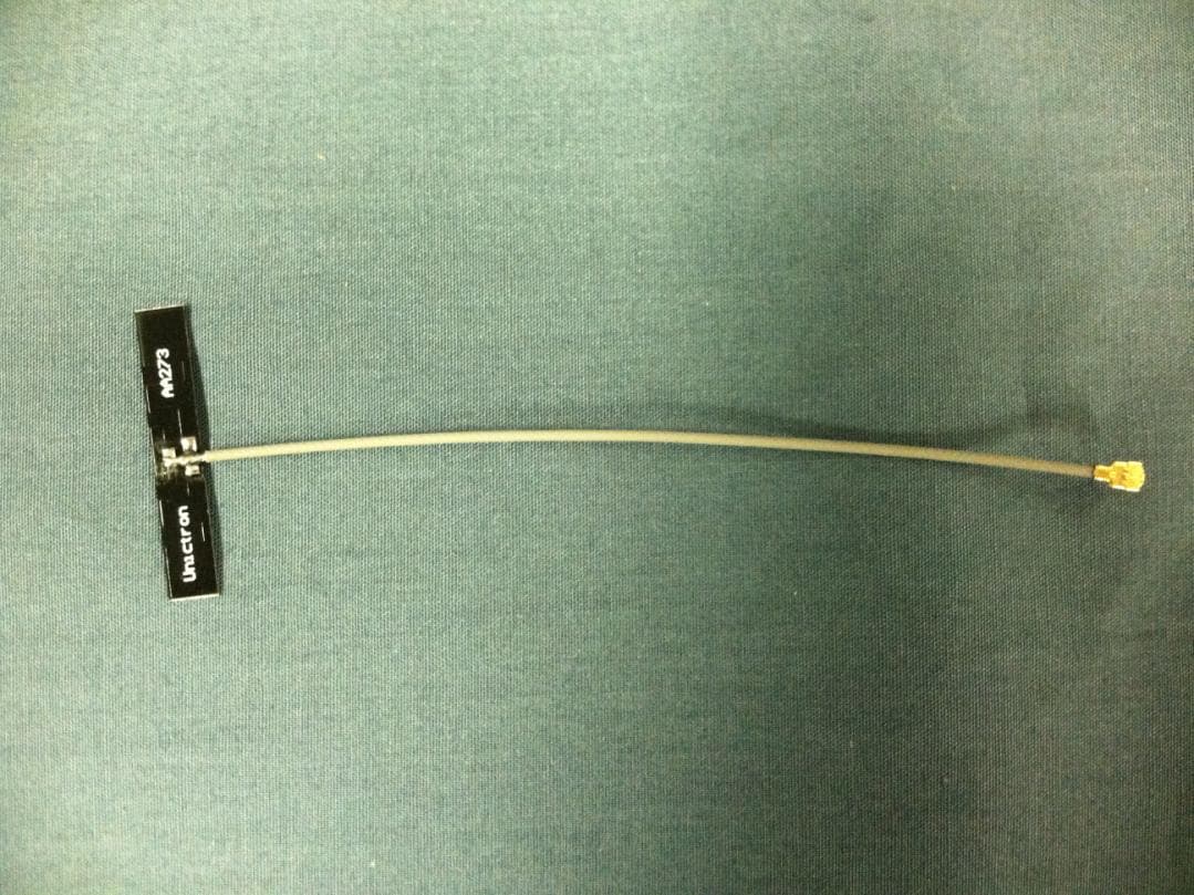
Click to zoom
Application Details
- Equipment Class
- DTS - Digital Transmission System
- Date of Grant
- Aug 04, 2013
- Application Purpose
- Original Equipment
- Date of Application
- Aug 04, 2013
- Equipment Note
- 802.11 TYPE WIFI MODULE
- Frequency Range
- 2412.00000000 - 2462.00000000
- Company
- Inventek Systems
- Country
- United States
Documents & Files
Document Text
Text extracted from the exhibit documents filed with the FCC. Open a document above to read the original.
Users Manual
_____________________________________________________________________________________________ Inventek Systems - www.Inventeksys.com 2 Republic Road • Billerica, MA 01862 • Phone 978-667-1962 Product Specification 1 Inventek Systems ISM43362-M3x-L44 Embedded Serial-to-Wi-Fi Module eS-WiFi TM 802.11 b/g/n Preliminary Data Sheet ISM43362-M3X Product Specification _____________________________________________________________________________________________ Inventek Systems DOC-DS-20023-2.1 2 Table of Contents 1 GENERAL DESCRIPTION ................................................................................................... 4 2 PART NUMBER DETAIL DESCRIPTION .......................................................................... 5 2.1 Ordering Information ...................................................................................................... 5 3 GENERAL FEATURES ......................................................................................................... 5 3.1 Limitations ...................................................................................................................... 6 3.2 Regulatory Compliance .................................................................................................. 6 3.3 FCC User’s Manual Statements ( In Process ): .............................................................. 7 3.4 Industry Canada User’s Manual Statements: .................................................................. 9 4 COMPLEMENTARY DOCUMENTATION ...................................................................... 10 4.1 Inventek Systems .......................................................................................................... 10 5 SPECIFICATIONS ............................................................................................................... 10 5.1 Module Architecture ..................................................................................................... 10 5.2 External Antenna Connections ..................................................................................... 11 5.3 Mechanical Specifications ............................................................................................ 11 5.4 Environmental Specifications ....................................................................................... 12 6 HARDWARE ELECTRICAL SPECIFICATIONS ............................................................. 12 6.1.1 Absolute Maximum Ratings ..................................................................................... 12 6.1.2 Recommended Operating Ratings ............................................................................ 12 6.2 Power Consumption ...................................................................................................... 13 6.2.1 Estimated Power Consumption ................................................................................. 13 6.2.2 Stop Mode ................................................................................................................. 13 7 Pin out ................................................................................................................................... 14 7.1.1 Detailed Pin Description ........................................................................................... 15 7.1.2 Configuration Pins: ................................................................................................... 16 *Requires a 10K ohm pull down .............................................................................................. 16 8 AC CHARACTERISTICS ................................................................................................... 16 8.1 UART ............................................................................................................................ 16 8.1.1 Data Mode ................................................................................................................. 16 8.1.2 2.1.2 Flow Control .................................................................................................... 16 8.1.3 2.1.3 Supported Baud Rates ...................................................................................... 17 8.1.4 Default Serial Configuration ..................................................................................... 17 8.2 SPI (Serial Peripheral Interface Bus) ............................................................................ 17 8.2.1 SPI Communication Overview: ................................................................................ 18 8.2.2 SPI Command Phase: ................................................................................................ 18 8.2.3 SPI Data Phase: ......................................................................................................... 19 8.2.4 SPI Asynchronous Messages: ................................................................................... 19 8.2.5 SPI AC Characteristics: ............................................................................................ 20 8.3 USB ............................................................................................................................... 20 8.4 GPIO ............................................................................................................................. 20 8.5 ADC’s ........................................................................................................................... 20 9 Wi-Fi RF Specification ......................................................................................................... 21 9.1.1 RF Specification........................................................................................................ 21 ISM43362-M3X Product Specification _____________________________________________________________________________________________ Inventek Systems DOC-DS-20023-2.1 3 10 Antenna Patterns ...............…
Text truncated - open the document above for the full version.
Cover Letter(s)
July 25, 2013 Applications Examiner RE: Modular Approval for Inventek Systems, FCC ID: O7P-326 Dear Application Examiner: Regarding Part 15 Unlicensed Modular Transmitter Approval, the following requirements called out in FCC Public Notice DA 00-1407 are observed: 1) The modular transmitter must have its own RF shielding. This is intended to ensure that the module does not have to rely upon the shielding provided by the device into which it is installed in order for all modular transmitter emissions to comply with Part 15 limits. It is also intended to prevent coupling between the RF circuitry of the module and any wires or circuits in the device into which the module is installed. Such coupling may result in non-compliant operation. The radio is a completely self contained radio which has its own RF shielding on the RF section. No other RF shielding is required or implemented. 2) The modular transmitter must have buffered modulation/data inputs (if such inputs are provided) to ensure that the module will comply with Part 15 requirements under conditions of excessive data rates or overmodulation. The radio is a completely self contained radio which modulates its own RF transmitter. It controls the data flow to the transmitter section compliant with Part 15 requirements. 3) The modular transmitter must have its own power supply regulation. This is intended to ensure that the module will comply with Part 15 requirements regardless of the design of the power supplying circuitry in the device into which the module is installed. THE radio module contains power supply building blocks and has its own power supply regulation, including a switching regulator, four LDO’s and a power amplifier LDO. 4) The modular transmitter must comply with the antenna requirements of Section 15.203 and 15.204(c). The antenna must either be permanently attached or employ a “unique” antenna coupler (at all connections between the module and the antenna, including the cable). Any antenna used with the module must be approved with the module, either at the time of initial authorization or through a Class II permissive change. The “professional installation” provision of Section 15.203 may not be applied to modules. For this application the radio employs a permanently attached antenna or has a unique antenna connector only. 5) The modular transmitter must be tested in a stand-alone configuration, i.e., the module must not be inside another device during testing. This is intended to demonstrate that the module is capable of complying with Part 15 emission limits regardless of the device into which it is eventually installed. Unless the transmitter module will be battery powered, it must comply with the AC line conducted requirements found in Section 15.207. AC or DC power lines and data input/output lines connected to the module must not contain ferrites, unless they will be marketed with the module (see Section 15.27(a)). The length of these lines shall be length typical of actual use or, if that length is unknown, at least 10 centimeters to insure that there is no coupling between the case of the module and supporting equipment. Any accessories, peripherals, or support equipment connected to the module during testing shall be unmodified or commercially available (see Section 15.31(i)). The module itself was tested while connected to an evaluation board. The evaluation board was provided as a means to communicate with the radio through the serial connection. Nothing on the evaluation board contributes to the performance of the radio, therefore the radio is considered to have been tested in a stand alone configuration. 6) The modular transmitter must be labeled with its own FCC ID number, and, if the FCC ID is not visible when the module is installed inside another device, then the outside of the device into which the module is installed must also display a label referring to the enclosed module. This exterior label can use wording such as the following: “Contains Transmitter Module FCC ID: XYZMODEL1” or “Contains FCC ID: XYZMODEL1.” Any similar wording that expresses the same meaning may be used. The Grantee may either provide such a label, an example of which must be included in the application for equipment authorization, or, must provide adequate instructions along with the module which explain this requirement. In the latter case, a copy of these instructions must be included in the application for equipment authorization. The radio consists of a printed circuit board, which is labeled with the FCC identification number. This PCB can be mounted in a host of devices and each device that this PCB utilizes will have the FCC ID number visible to the consumer. 7) The modular transmitter must comply with any specific rule or operating requirements applicable to the transmitter and the manufacturer must provide adequate instructions along with the module to explain any such requirements. A copy of these instructions must be included in the application for equipment authorization. For example, there are very strict operational and timing requirements that must be met before a transmitter is authorized for operation under Section 15.231. For instance, data transmission is prohibited, except for operation under Section 15.231(e), in which case there are separate field strength level and timing requirements. Compliance with these requirements must be assured. The radio comes equipped with embedded firmware that controls these parameters. 8) The modular transmitter must comply with any applicable RF exposure requirements. For example, FCC Rules in Sections 2.1091, 2.1093 and specific Sections of Part 15, including 15.319(i), 15.407(f), 15.253(f) and 15.255(g), require that Unlicensed PCS, UNII and millimeter wave devices perform routine environmental evaluation for RF Exposure to demonstrate compliance. In addition, spread spectrum transmitters operating under Section 15.247 are required to address RF Exposure compliance in a…
Text truncated - open the document above for the full version.
Cover Letter(s)
Request for Confidentiality Date: July 25, 2013 Subject: Confidentiality Request for: FCC ID: O7P-362 and IC: 10147A-362 Pursuant to FCC 47 CRF 0.457(d) and 0.459 and IC RSP-100, Section 10, the applicant requests that a part of the subject FCC application be held confidential. Type of Confidentiality Requested Exhibit Short Term Permanent Block Diagrams Short Term Permanent Schematics Short Term Permanent Theory of Operation The Applicant has spent substantial effort in developing this product and it is one of the first of its kind in industry. Having the subject information easily available to "competition" would negate the advantage they have achieved by developing this product. Not protecting the details of the design will result in financial hardship. Permanent Confidentiality: The applicant requests the exhibits listed above as permanently confidential and be permanently withheld from public review due to materials that contain trade secrets and proprietary information not customarily released to the public. Sincerely, By: __________________________ ___Sandi McEnery______________ (Signature/Title) (Print name)
External Photos
US Tech Test Report: FCC Part 15 Certification IC-RSS Certification FCC ID: O7P-362 IC: 10147A-362 Test Report Number: 13-0186 Issue Date: July 29, 2013 Customer: Inventek Systems Model: ISM43362-M3G-L44-E and ISM43362-M3G-L44-U Page 1 of 4 External and Antenna Photographs Figure 1- Radio Module on Board US Tech Test Report: FCC Part 15 Certification IC-RSS Certification FCC ID: O7P-362 IC: 10147A-362 Test Report Number: 13-0186 Issue Date: July 29, 2013 Customer: Inventek Systems Model: ISM43362-M3G-L44-E and ISM43362-M3G-L44-U Page 2 of 4 Figure 2 - Radio Module - Rear View US Tech Test Report: FCC Part 15 Certification IC-RSS Certification FCC ID: O7P-362 IC: 10147A-362 Test Report Number: 13-0186 Issue Date: July 29, 2013 Customer: Inventek Systems Model: ISM43362-M3G-L44-E and ISM43362-M3G-L44-U Page 3 of 4 Figure 3. Radio Module with Trace Antenna - Top View US Tech Test Report: FCC Part 15 Certification IC-RSS Certification FCC ID: O7P-362 IC: 10147A-362 Test Report Number: 13-0186 Issue Date: July 29, 2013 Customer: Inventek Systems Model: ISM43362-M3G-L44-E and ISM43362-M3G-L44-U Page 4 of 4 Figure 4 - Dipole Antenna u.fl connector to radio module.
ID Label/Location Info
SAMPLE LABEL FOR MODEL ISM43362-M3G-L44-E SAMPLE LABEL FOR MODEL ISM43362-M3G-L44-U
Internal Photos
US Tech Test Report: FCC Part 15 Certification IC: RSS-210 Certification FCC ID: O7P-362 IC: 1047A-362 Test Report Number: 13-0186 Issue Date: July 25, 2013 Customer: Inventek Systems Model: ISM43362-M3G-L44-E and ISM43362-M3G-L44-U Page 1 of 1 Internal Photographs Figure 1- Shielding Removed
RF Exposure Info
US Tech Test Report: FCC Part 15 Certification IC RSS210-Certification FCC ID: O7P-362 IC: 10147A-362 Test Report Number: 13-0186 Issue Date: July 29, 2013 Customer: Inventek Systems Model: ISM43362-M3G-L44-E and ISM43362-M3G-L44-U Page 1 of 1 Maximum Public Exposure to RF (MPE) CFR 15.247 (i) The maximum exposure level to the public from the RF power of the EUT shall not exceed a power density, S, of 1 mW/cm 2 at a distance, d, of 20 cm from the EUT. Therefore, for: Highest Gain Dipole Antenna= 2.15 dBi Peak Power (Watts) = 0.0977 (from Table 19 of Test Report) Gain of Transmit Antenna = 2.15 dB i = 1.641, numeric (from Table 4 of Test Report) d = Distance = 20 cm = 0.2 m S = (PG/ 4d 2 ) = EIRP/4A = 0.0977(1.641)/4*π*0.2*0.2 = 0.1603/0.503 = 0.3187 W/m 2 = (W/m 2 ) (1m 2 /W) (0.1 mW/cm 2 ) = 0.03187 mW/cm 2 which is << less than 1.0 mW/cm 2 Highest Gain Trace Antenna= 0 dBi Peak Power (Watts) = 0.0977 (from Table 19 of Test Report) Gain of Transmit Antenna = 0 dB i = 1.0, numeric (from Table 4 of Test Report) d = Distance = 20 cm = 0.2 m S = (PG/ 4d 2 ) = EIRP/4A = 0.0977(1)/4*π*0.2*0.2 = 0.0977/0.503 = 0.1942 W/m 2 = (W/m 2 ) (1m 2 /W) (0.1 mW/cm 2 ) = 0.01942 mW/cm 2 which is << less than 1.0 mW/cm 2
Test Report
Application For Title 47 USC, Part 2, Subpart J, Paragraph 2.902, Equipment Authorization of Verification for an Unintentional Radiator per Part 15, Subpart B, Paragraphs 15.107 and 15.109 And Part 2, Subpart J, Paragraph 2.907 Equipment Authorization of Certification for an Intentional Radiator per Part 15, Subpart C, paragraph 15.247 For the Inventek Systems Models: ISM43362-M3G-L44-E and ISM43362-M3G-L44-U FCC ID: O7P-362 IC: 10147A-362 UST Project: 13-0186 Issue Date: July 29, 2013 Total Pages: 122 3505 Francis Circle Alpharetta, GA 30004 PH: 770-740-0717 Fax: 770-740-1508 www.ustech-lab.com I certify that I am authorized to sign for the Test Agency and that all of the statements in this report and in the Exhibits attached hereto are true and correct to the best of my knowledge and belief: US TECH (Agent Responsible For Test): By: Alan Ghasiani Name: Title: Compliance Engineer – President Date: July 25, 2013 This report shall not be reproduced except in full. This report may be copied in part only with the prior written approval of US Tech. The results contained in this report are subject to the adequacy and representative character of the sample provided. 3505 Francis Circle Alpharetta, GA 30004 PH: 770-740-0717 Fax: 770-740-1508 www.ustech-lab.com US Tech Test Report: FCC Part 15 Certification & IC RSS FCC ID: O7P-362 IC ID: 10147A-362 Test Report Number: 13-0186 Issue Date: July 29, 2013 Customer: Inventek Systems Model(s): ISM43362-M3G-L44-E and ISM43362-M3G-L44-U Page 3 of122 MEASUREMENT TECHNICAL REPORT COMPANY NAME: Inventek Systems MODEL(S): ISM43362-M3G-L44-E and ISM43362-M3G-L44-U FCC ID: O7P-362 IC ID: 10147A-362 DATE: July 25, 2013 This report concerns (check one): Original grant X Class II change Equipment type: DSSS WiFi module for use in other devices. Deferred grant requested per 47 CFR 0.457(d)(1)(ii)? yes_____ No X If yes, defer until: ______N/A___________date agrees to notify the Commission by N/A date of the intended date of announcement of the product so that the grant can be issued on that date. Report prepared by: US Tech 3505 Francis Circle Alpharetta, GA 30004 Phone Number: (770) 740-0717 Fax Number: (770) 740-1508 US Tech Test Report: FCC Part 15 Certification & IC RSS FCC ID: O7P-362 IC ID: 10147A-362 Test Report Number: 13-0186 Issue Date: July 29, 2013 Customer: Inventek Systems Model(s): ISM43362-M3G-L44-E and ISM43362-M3G-L44-U Page 4 of122 Table of Contents Paragraph Title Page 1 General Information .......................................................................................... 10 1.1 Purpose of this Report ............................................................................... 10 1.2 Characterization of Test Sample ............................................................... 10 1.3 Product Description ................................................................................... 10 1.4 Configuration of Tested System ................................................................ 11 1.5 Test Facility ............................................................................................... 11 1.6 Related Submittal(s)/Grant(s) .................................................................... 11 2 Tests and Measurements ................................................................................. 13 2.1 Test Equipment ......................................................................................... 13 2.2 Modifications to EUT Hardware ................................................................. 14 2.3 Number of Measurements for Intentional Radiators (15.31(m)) ................. 14 2.4 Frequency Range of Radiated Measurements (Part 15.33) ...................... 15 2.5 Measurement Detector Function and Bandwidth (CFR 15.35) .................. 15 2.6 EUT Antenna Requirements (CFR 15.203) ............................................... 16 2.7 Restricted Bands of Operation (Part 15.205) ............................................. 18 2.8 Transmitter Duty Cycle (CFR 35 (c)) ......................................................... 18 2.9 Intentional Radiator, Power Lines Conducted Emissions (CFR 15.207) .... 20 2.10 Intentional Radiator, Radiated Emissions (Antenna Conducted) (CFR 15.209, 15.247(d)) (IC RSS 210, A2.9 (a)) ........................................................... 21 2.10.1 Conducted Radiated Emissions, IEEE 802.11b, Channel 1 ............... 23 2.10.2 Conducted Radiated Emissions, IEEE 802.11b, Channel 7 ............... 27 2.10.3 Conducted Radiated Emissions, IEEE 802.11b, Channel 11 ............. 31 2.10.4 Conducted Radiated Emissions, IEEE 802.11g, Channel 1 ............... 35 2.10.5 Conducted Radiated Emissions, IEEE 802.11g, Channel 7 ............... 39 2.10.6 Conducted Radiated Emissions, IEEE 802.11g, Channel 11 ............. 43 2.10.7 Conducted Radiated Emissions, IEEE 802.11n, Channel 1 ............... 47 2.10.8 Conducted Radiated Emissions, IEEE 802.11n, Channel 7 ............... 51 2.10.9 Conducted Radiated Emissions, IEEE 802.11n, Channel 11 ............. 55 2.11 Intentional Radiated Emissions and Harmonics ........................................ 59 2.12 6 dB Bandwidth per CFR 15.247(a)(2), (IC RSS 210, A8.2(a)) ................. 71 2.13 Maximum Peak Conducted Output Power (CFR 15.247 (b) (3)) ............... 81 2.14 Power Spectral Density (CFR 15.247(e)) (IC RSS 210 A8.5) .................... 92 2.15 Band Edge Measurements-(CFR 15.247 (d)) .......................................... 102 2.16 20 dB Bandwidth Measurement per CFR 15.247, 99% Occupied Bandwidth (IC RSS 210, A8.1) ............................................................................................. 109 2.17 Unintentional Radiator Power Lines Conducted Emissions (CFR 15.107) 119 2.18 Unintentional Radiator, Radiated Emissions (CFR 15.109, 15.209) ........ 121 US Tech Test Report: FCC Part 15 Certification & IC RSS FCC ID: O7P-362 IC ID: 10147A-362 Test Report Number: 13-0186 Issue Date: July 29, 2013 Customer…
Text truncated - open the document above for the full version.
Test Setup Photos
US Tech Test Report: FCC Part 15 Certification FCC ID: O7P-362 IC: 10147A-362 Test Report Number: 13-0186 Issue Date: July 29, 2013 Customer: Inventek Systems Model: ISM43362-M3G-L44-E and ISM43362-M3G-L44-U Page 1 of 5 Test Configuration Photographs Figure 1- Radiated Emissions Test configuration US Tech Test Report: FCC Part 15 Certification FCC ID: O7P-362 IC: 10147A-362 Test Report Number: 13-0186 Issue Date: July 29, 2013 Customer: Inventek Systems Model: ISM43362-M3G-L44-E and ISM43362-M3G-L44-U Page 2 of 5 Figure 2- Radiated Emissions, Log Periodic Antenna US Tech Test Report: FCC Part 15 Certification FCC ID: O7P-362 IC: 10147A-362 Test Report Number: 13-0186 Issue Date: July 29, 2013 Customer: Inventek Systems Model: ISM43362-M3G-L44-E and ISM43362-M3G-L44-U Page 3 of 5 Figure 3- Radiated Emissions, Bicon Antenna US Tech Test Report: FCC Part 15 Certification FCC ID: O7P-362 IC: 10147A-362 Test Report Number: 13-0186 Issue Date: July 29, 2013 Customer: Inventek Systems Model: ISM43362-M3G-L44-E and ISM43362-M3G-L44-U Page 4 of 5 Figure 4- Radiated Emissions, Loop Antenna US Tech Test Report: FCC Part 15 Certification FCC ID: O7P-362 IC: 10147A-362 Test Report Number: 13-0186 Issue Date: July 29, 2013 Customer: Inventek Systems Model: ISM43362-M3G-L44-E and ISM43362-M3G-L44-U Page 5 of 5 Figure 5- Conducted Emissions Test Setup
Contact Information
Applicant
Martin Tierney(President)
Test Firm
US TechGeorge Yang
Technical Specifications
| # | Rule Parts | Frequency Range | Power Output |
|---|---|---|---|
| 1 | 15C | 2.41 GHz - 2.46 GHz | 97.70 mW |
Other Applications from Inventek Systems
O7P-2531F
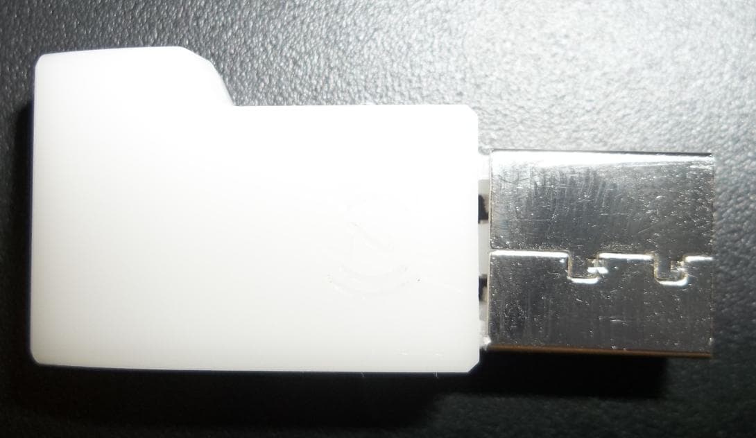
Nov 20, 20142.4 GHz USB Dongle
Equipment Class
DTS - Digital Transmission System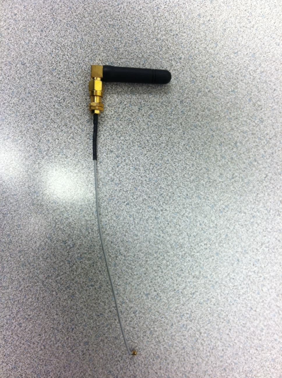
O7P-ISM4319F1
Aug 13, 2012WIFI MODULE
Equipment Class
DTS - Digital Transmission System