OA4IME250
Safeguards Technology, LLC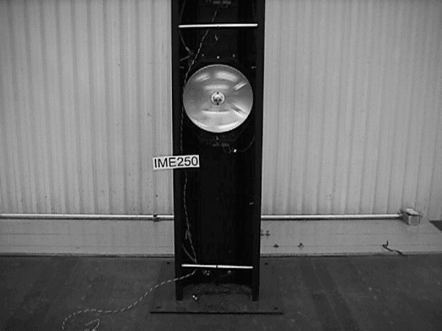
Click to zoom
Application Details
- Equipment Class
- FDS - Part 15 Field Disturbance Sensor
- Date of Grant
- Mar 30, 1999
- Application Purpose
- Original Equipment
- Date of Application
- Feb 23, 1999
- Frequency Range
- 10526.50000000 - 10526.50000000
- Company
- Safeguards Technology, LLC
- Country
- United States
Documents & Files
Document Text
Text extracted from the exhibit documents filed with the FCC. Open a document above to read the original.
Users Manual
PRINCIPLES OF OPERATION................................................................. 3 INSTRUCTIONS FOR INSTALLATION.................................................... 3 ORIENTATION ......................................................................................... 4 INSTALLATION SITE ............................................................................... 4 PLACING THE UNIT IN PROXIMITY OF BUILDINGS............................. 5 REMOVAL OF THE PROTECTORS, ASSEMBLY................................... 5 POWER SUPPLY ..................................................................................... 5 ELECTRICAL CONNECTIONS ................................................................ 6 CONNECTION BETWEEN THE TWO COLUMNS ................................ 10 CONNECTIONS TO THE CONTROL PANEL........................................ 10 LEDS AND FUSES OF THE RECEIVER................................................ 10 LEDS AND FUSES OF THE TRANSMITTER ........................................ 11 IR SETTING, CABLING AND INSTALLING ........................................... 11 ALIGMENT AND CALIBRATION OF THE MICROWAVE SHEAF ......... 18 INSTALLING THE MW DOPPLER DEVICE........................................... 21 ASSEMBLY ............................................................................................. 21 TIMING THE TWO TECHNOLOGIES .................................................... 22 CLOSING THE COLUMNS..................................................................... 23 IR SPECIFICATIONS.............................................................................. 23 MW SPECIFICATIONS........................................................................... 23 CAUTION CHANGES OR MODIFICATIONS NOT EXPRESSLY APPROVED BY SAFEGUARDS TECHNOLOGY INC COULD VOID THE USERS AUTHORITY TO OPERATE THIS DEVICE PRINCIPLES OF OPERATION ABSOLUTE is a double-technology appliance for outdoor installation, enclosed in two columns made of aluminium extrudate. This completely new combination of outdoor detectors allows perimetral protection with coverage of up to 150 m. Microwave technology, combined with infrared sensors, eliminates the possibility of false alarms while maintaining high security standards. The microwave and active infrared signals are received and processed individually: the activation of the alarm signal comes as a result of precise synchronisms and a sophisticated coordination between the two technologies. Surveillance is carried out by means of a temporary window memory circuit. The pilot circuits of both detection technologies are equipped with a timer whose range is from 20 seconds to 2 minutes. The first device that receives a stimulus activates its own timer. During this time the other technology will be summoned to confirm the final alarm. Through this method of operation, false alarms caused by environmental factors are eliminated. The microwave device is the one that functions as the “activator” because, in most cases, it is activated first. Its detection capacity is determined by a lobe that can be regulated with its own trimmer. In a case where the infrared disqualification circuits start functioning, the sensibility of the microwave device decreases automatically, and during this time span (of disqualification) the barrier functions using one technology only. Moreover, as an option, an anti- crawling device can be installed, in case there are no crossing columns. In such cases, a Doppler short-beam microwave device is employed. This covers the blind zone in proximity to the barriers. In its basic configuration, ABSOLUTE is equipped with two pairs of active infrared devices, of which one is master and one slave. The transmitter sends a modulated infrared beam in the direction of the receiver. The receiver does not recognize continuous (unmodulated) infrared or visible signals: therefore it is completely immune to sunlight. The built-in disqualifying circuits de-activate the active infrared device in case of an attenuation of the signal, e.g. by fog, heavy rain or snowfall. INSTRUCTIONS FOR INSTALLATION Position the appliance in a sufficiently open area, strategically optimal for protection of the site. Local conditions must be thoroughly evaluated in advance so that the zone to be protected is delimited by the double technology sensor, physical obstacles like walls, fences and ditches or other systems of anti- intrusion surveillance. ORIENTATION The installation of the appliance requires that the transmitters and receivers placed in the two columns face each other, so that the two technologies may be aligned. INSTALLATION SITE The installation site must be chosen in such a way that the transmitters and the receivers are on the same level. Installation in sites with significant terrain irregularities must be avoided. If this is not done, blind zones for the microwaves as well as the infrared signals may occur, through which a trespasser could find his way in. The installator must also avoid positioning the appliance in zones with objects lying between the receiver and the transmitter (trees, bushes, etc.), as these could cause false alarms. Attention must be paid to the surface as well. If it is grass, it is important to trim it regularly in order to avoid its movement interfering with the microwave signal. If the installation is done on asphalt, the microwave must be raised by 20 cm, as described in chart TAB 1, page 13. This is necessary in order to avoid interference generated by reflections when the asphalt is wet. PLACING THE UNIT IN THE PROXIMITY OF BUILDINGS If the installation is to be done in the proximity of buildings, several rules must be followed: Metal Nets In order to avoid reflections that could create interference, position the columns in such a way that the appliance main axis is at a distance of at least 2 m from the maximum diameter formed by the microwave. This is because casual movements or vibrations of the metal nets caused…
Text truncated - open the document above for the full version.
ID Label/Location Info
Safeguards Technologies, 75 Atlantic Ave., Hackensack, N.J. 07601-4132 DRAFT OF FCC ID LABEL TO BE SUBMITTED FOR CERTIFICATION FCC ID: 0A4IME250 ABSOLUTE DUAL TECHNOLOGY EXTERIOR SENSOR This device complies with Part 15 of the FCC Rules. Operation is subject to the following two conditions: (1) this device may not cause harmful interference and (2) this device must accept any interference received, including interference that may cause undesired operation. SENSOR TOP REAR VIEW OF SENSOR 70 IN.
Operational Description
Electric diagram and microwave-transmitter block diagram functioning description. Block nr.1 Block nr. 1 turns the alternating voltage applied to terminals 7 and 8 of the microwave into a rectified voltage needed to supply the voltage control of block nr. 2. Block nr.2 Block nr.2 regulates the rectified voltage at about 13,65V d.c.. This voltage allows to recharge an eventual floating battery and supplies the input voltage to the voltage control at 5V d.c. necessary to supply the logical processing circuit of the received signal. Block nr.3 Block nr.3 protects the circuit from eventual faults due to a polarity inversion of the eventually applied battery. Block nr.4 Block nr.4 consists of the parabola antenna and of the cavity which receive the signal in frequency emitted by the transmitter, and transformed into a sinusoidal input signal of the amplifier. Block nr.5 Block nr.5 consists of the two amplification transistors with corresponding polarization networks that allow to amplify the signal coming from the cavity. The signal will be even more amplified by operational U2B and corresponding polarization network. Block nr.6 and 7 Block nr.6, consisting of the dip-switch and the double exchange relay, selects the functioning mode of the microwave. During the test mode (alignment) the relay allows the breaking of the signal so as to inhibit the functioning of the automatic gain regulator during the alignment phases of the microwave. Block nr.8 Block nr.8 consists of the potentiometric trimmer R18, that allows to manually regulate the quantity of amplified signal to allow the alignement of the microwave with voltage values far from the saturation threshold of the amplifier. Block nr.9 Block nr.9 selects the frequency channel to compare with the received one. This selection takes place thanks to the dip-switch DV1. With all the dips in OFF position frequency nr.1=900Hz is achieved. With dip 1 in ON position freqency nr.2=1160Hz is achieved With dip 2 in ON position frequency nr.3=1500Hz is achieved With all dips in ON position frequency nr.4=2400Hz is achieved Block nr.10 Block nr.10 allows to filter the non-correlated frequencies with those received through the group of resistances and capacitors and the operational I1A. In output from this group there will be then a sinusoidal signal sufficient only when the frequency of the received sinusoid and the sinusoid selectioned on the receiver are in accordance. Block nr.11 Block nr.11 amplifies (U2A and corresponding polarization network) in a definite way only the received signal having a frequency corresponding to the one selected. Block nr.12 This block turns the amplified and received signal into a constant level rectified signal through the diode, capacitor and operational U3B rectification group. Block nr.13 Block nr.13 consists of the gain automatic regulation group(A.G.C.) that stabilizes the received signal at a constant level through U3A and transistor Q3. Block nr.14 This group (U5B) allows to have the rectified and stabilized signal in output at terminal M1 that allows the correct alignment of the microwave pair. Block nr.15 and 16 In this block the constant signal (comp) in output from the amplification group is integrated through the trimmer and the capacitor(R62, C27) that allow to control in installment phase the adjustment of the surveying modes of the object crossing the microwave in a more or less fast way. Block nr.17 This group (U4A and B) sets the alarm thresholds. In fact the outputs of these operationals are activated every time the rectified signal leaves the alarm window determined by the calibration of trimmer R45. The alarm thresholds are increased in case a pilot signal is sent to terminal 6. Block nr.18 Block nr.18 allows to stop the microwave functioning through an external signal applied to terminal M5. Block nr.19 Block nr.19 includes the control of the Darlington type transistor Q5 that allows to control the alarm relay. Block nr.20 The alarm relay supplies an exchange contact free of potentials for connections of the microwave to alarm control panels. Electric diagram and microwave-transmitter block diagram functioning description. Block nr.1 Block nr.1 turns the alternate voltage applied to terminals 7 and 8 of the microwave into a rectified voltage necessary to supply the voltage regulator of block 2. Block nr.2 Block nr.2 carries out an adjustment of the rectified voltage at about 13,65 d.c.. This voltage allows to recharge an eventual floating battery and supplies the input voltage for the adjusted supply voltage of the cavity driver and circuit logic pilot circuit . Block nr.3 Block nr.3 protects the circuit from eventual faults due to polarity inversion of the eventually applied battery. Block nr.4 Block nr.4 presets the oscillation frequency of the frequency generating circuit consisting of the operational group U1B. The presetting of the oscillation frequency takes place short-circuiting common terminal M9 with terminals M5, M6, M7, M8. Short-circuiting terminal M9 with M5 frequency nr.1= 900Hz +/- 5% is achieved. Short-circuiting terminal M9 with M6 frequency nr.2=1160Hz +/- 5% is achieved. Short-circuiting terminal M9 with M7 frequency nr.3=1500Hz +/- 5% is achieved. Short-circuiting terminal M9 with M8 frequency nr.4=2400Hz +/- 5% is achieved. Block nr.5 Oscillation block nr.5 forms the frequency square wave equal to the one preset in block nr.4. Block nr.6 Block nr.6 is the cavity control. The square wave form coming out of operational U1B controls the two control transistors that allow to have a higher power to control the cavity at disposition. Block nr.7 Block nr.7 consisting of the cavity and of the emitter parable allows to give rise to the sinusoidal frequency emitted by the antenna which is the frequency signal emitted by the transmitter.
Parts List/Tune Up Info
MWTX DateJan141999* * COMPONENTLIST Transmitter Microwave BEGIN P.C.B. Boardn° 3117 Electrolytic CapacitorC2 220uF16V, Ceramic Capacitor SMDC4 100nF25V, Polyester Capacitor C5 10nF25V, Ceramic Capacitor SMDC6 100nF25V, Ceramic Capacitor C7 10nF25V,5% Ceramic Capacitor SMDC8 100nF25V, Electrolytic CapacitorC9 220uF16V, Ceramic Capacitor SMDC10 100nF25V, Electrolytic CapacitorC11 470uF16V, Electrolytic CapacitorC12 1000uF50V, Ceramic Capacitor SMDC13 100nF50V, Ceramic Capacitor SMDC14 100nF50V, Ceramic Capacitor SMDC15 100nF50V, Ceramic Capacitor SMDC16 10pF50V, Ceramic Capacitor SMDC17 100nF25V, Ceramic Capacitor SMDC19 100nF25V, Electrolytic CapacitorC20 100uF16V, Electrolytic CapacitorC21 100uF16V, Diode Mini Melf SMDD2 LL4148 Diode Mini Melf SMDD3 LL4148 DiodeD4 1N4001 DiodeD5 1N4001 DiodeD6 1N4001 DiodeD7 1N4001 DiodeD8 1N4001 DiodeD9 1N4001 DiodeD11 1N4001 DiodeD12 1N4001 DiodeD13 1N4001 FuseF1 1As.r.5X20 FuseF2 1As.r.5X20 FuseF3 1As.r.5X20 LampLP 1 24V5W ChokeL1 10uHr ChokeL2 10uHr ChokeL3 10uHr Transistor PNP DarlingtonQ2 BCW68B Transistor PNP DarlingtonQ3 BCW68B Resistor Chip SMD 1221R2 1001/8W,5% Resistor Chip SMD 1220R3 5601/8W,5% Resistor Chip SMD 1206R4 2K21/4W,5% Resistor Chip SMD 1224R5 100K1/8W,5% Resistor Chip SMD 1206R6 10K1/4W,5% Resistor Chip SMD 1206R7 1M1/8W,5% Resistor Chip SMD 1206R8 10K1/8W,5% Resistor Chip SMD 1207R9 10K1/8W,5% Pagina 1 MWTX Resistor Chip SMD 1208R10 47K1/8W5% Resistor Chip SMD 1209R11 33K1/8W,5% Resistor Chip SMD 1211R12 27K1/8W,5% Resistor Chip SMD 1213R13 15K1/8W,5% Trimmer Multi-TurnR14 5K1/8W,5% Trimmer Multi-TurnR15 5K1/8W,5% Trimmer Multi-TurnR16 5K1/8W,5% Trimmer Multi-TurnR17 5K1/8W,5% Resistor Chip SMD 1223R18 1K1/8W,5% Resistor Chip SMD 1216R19 47K1/8W,5% Resistor Chip SMD 1218R20 100K1/8W,5% Resistor Chip SMD 1217R21 100K1/8W,5% Resistor Chip SMD 1222R22 1K1/8W,5% Trimmer Multi-TurnR23 2K1/8W,5% Resistor Chip SMD 1223R24 4K71/8W,5% Resistor Chip SMD 1223R25 1K1/8W,5% Trimmer Multi-TurnR26 2K1/8W,5% Resistor Chip SMD 1225R27 10K1/8W,5% Resistor Chip SMD 1219R28 4K71/8W,5% Resistor Chip SMD 1223R29 470K1/4W,5% Resistor Chip SMD 1210R30 470K1/8W,5% Resistor Chip SMD 1212R31 470K1/8W,5% Resistor Chip SMD 1214R32 470K1/8W,5% Resistor Chip SMD 1215R33 2M21/8W,5% Dual Operational AmplifierU1 LM2903DIL 8 PIN SMD Voltage RegulatorU2 LM317TO220 Voltage RegulatorU3 LM317TO220 ZNRZ1 S10K30 ZNRZ2 S10K30 ZNRZ3 S07K14 END Pagina 2 MWTX Pagina 3 MWTX When adjust the frequency is possible to cut R29-R30-R31-R32 Pagina 4
Test Report
Test Report Number R-7845-1 REPORT OF MEASUREMENTS GENERAL Applicant:Safeguard Technology Inc. Device:10.525 GHz Field Disturbance Sensor Model:IME250 Serial Number:N/A FCC ID:OA4IME250 Input Power Requirements:24 VAC Rule Section:Part 15, Subpart C, Section 15.245 TEST METHODS PERFORMED 15.207 (a)Conducted Emissions, 450Khz to 30 MHz 15.245 (b)Radiated Emissions, Fundamental 15.245 (b)(1) Radiated Emissions, Harmonics 15.245 (b)(3) Radiated Emissions, Band Edges 15.245 (b)(3) Radiated Emissions, Spurious Emissions, 30 MHz to 52.625 GHz TEST RESULTS 15.245 (a)The device is an intentional radiator used as a field disturbance sensor. 15.245 (b)The device operates within the 10.500 to 10.550 GHz frequency band. The field strength of the fundamental emission did not exceed 2500 millivolts per meter, average. 15.245 (b)(1)The device does not produce harmonic emissions below 17.7 GHz. 15.245 (b)(1)(ii)The device is intended to be used outside of buildings and the field strength of harmonic emissions did not exceed 7.5 millivolts per meter. 15.245 (b)(2)All radiated emissions measurements were extrapolated to the specified 3 meter test distance. 15.245 (b)(3)The emissions radiated outside of the specified frequency band of 10.500 to Test Report Number R-7845-1 10.550 GHz did not exceed the general radiated emission limits of 15.209. 15.245 (b)(4)The requirements of 15.35 for averaging pulsed emissions and limiting peak emissions were met. NOTES 15.31 (a)(b)All measurements were made in accordance with ANSI C63.4:1992. 15.31 (c)The device does not use swept frequency techniques. 15.31 (d)All testing was performed on Retlif Testing Laboratories Ronkonkoma, NY test site, which has been listed with the FCC. 15.31 (e) Variation of the radiated signal level of the fundamental frequency component was performed with the supply voltage varied between 85% and 115% of the nominal rated supply voltage 15.31 (f)(1)Where testing was performed at distances other than the specified test distance, the obtained readings were extrapolated to the specified test distance using an inverse linear-distance extrapolation factor (20 dB / decade) for measurements between 30 MHz and 40 GHz. For measurements at frequencies above 40 GHz, an inverse linear-distance squared factor (40 dB / decade) was utilized. 15.31 (f)(5)The device was rotated 360 in order to maximize the radiated emissions. The maximum field strength observed has been reported. 15.31 (g)All consumer accessible controls were adjusted in order to maximize emissions 15.31 (m)The device operates at a single frequency of 10.5265 GHz. 15.31 (o)All emissions within 20 dB of the specified limits have been reported unless otherwise stated. 15.33 (a)(2)The device operates above 10 and below 30 GHz at a frequency of 10.525 GHz. Therefore radiated emissions measurements were made from 30 MHz to 52.625 GHz, the fifth harmonic. Test Report Number R-7845-1 DUTY CYCLE This device has a pulsed square wave output, with a maximum repetition frequency of 2400 Hz. This yields a duty cycle of 50.0%, 50.0 mSec divided by 100 mSec. This duty cycle was applied to the obtained peak readings in order to determine the average value of the emissions. TEST DISTANCES In order to obtain adequate system sensitivity at the harmonic frequencies of interest, it was necessary to perform certain measurements at a distance less than 3 meters. Care was taken to ensure that all measurements were taken in the far field region. The antenna was determined to be in the far field IFF: d 2 D 2 Where: d = Test Distance D = Largest Antenna Length = Wavelength at the Frequency of Interest Solving for d yields the minimum test distances shown in the table below. Also shown is the actual test distance utilized: Frequency GHz Minimum Test Distance Meters Actual Test Distance Meters 10.52652.73 21.05301.52 31.57951.03 42.10600.52 52.63250.71 Test Report Number R-7845-1 SPECTRUM ANALYZER DESENSITIZATION CONSIDERATIONS Due to the nature of the emissions being measured, care was taken to ensure that the resolution bandwidth of the spectrum analyzer was adequate to provide accurate peak field strength measurements. The following formula was utilized: Pulse Desensitization ( ) = 20 log (Pulsewidth * bandwidth * 1.5) Setting the above equal to zero and utilizing the 208.3 microsecond pulsewidth yields a minimum required bandwidth of 3200 Hz. The 1 MHz bandwidth specified in ANSI C63.4 was utilized for all fundamental and harmonic measurements. Test Report Number R-7845-1 TEST DATA RADIATED EMISSIONS, FUNDAMENTAL 15.245 (b) Test Report Number R-7845-1 TEST SAMPLE: 10.525 GHz Field Disturbance Sensor FCC ID: OA4IME250 APPLICANT: Safeguard Technology Inc. TEST METHOD: Radiated Emissions, Fundamental SPECIFICATION: FCC Part 15, Section 15.245 (b) PERFORMED BY: D. Cortes DATE: 1/26/99 Field Strength of Fundamental Frequency GHz Antenna Position H / V EUT Orientation X / Y/ Z Meter Reading dBuV Antenna Factor +dB Corrected Reading dBuV/m Converted Reading mV/m Limit at 3 Meters mV/m 10.5265HX96.36.7103.0141.32,500 VX107.46.7114.1507.02,500 HY80.46.787.122.62,500 VY84.26.790.935.12,500 Detector Function: Peak Test Distance: 3 Meters Resolution Bandwidth: 1 MHz Video Bandwidth: 3 MHz Test Report Number R-7845-1 TEST SAMPLE: 10.525 GHz Field Disturbance Sensor FCC ID: OA4IME250 APPLICANT: Safeguard Technology Inc. TEST METHOD: Radiated Emissions, Fundamental, Input Voltage Variation SPECIFICATION: FCC Part 15, Section 15.245 (b), 15.31(e) PERFORMED BY: D. Cortes DATE: 1/26/99 Input Voltage Variation Frequency GHz Test Voltage Test Voltage VAC Meter Reading dBuV Antenna Factor +dB Corrected Reading dBuV/m Converted Reading mV/m Limit at 3 Meters mV/m 10.5265 85% (Vmin) 20.4 VAC107.46.7114.1507.02,500 100% (Vnom) 24 VAC107.46.7114.1507.02,500 115% (Vmax) 27.6 VAC107.36.7114.0501.22,500 Detector Function: Peak Test Distance: 3 Meters Resolution Bandwidth: 1 MHz Video Bandwidth: 3 MHz Test Report Number R-7845-1 TEST D…
Text truncated - open the document above for the full version.
Contact Information
Applicant
Haim Perry(Executive Vice President)
Technical Contact
Retlif Testing LaboratoriesThomas J Schneider
[email protected]516-737-1500
795 Marconi Avenue · Ronkonkoma, New York · United States
Non-Technical Contact
Retlif Testing LaboratoriesMichelle F Tirado
[email protected]516-737-1500
Technical Specifications
| # | Rule Parts | Frequency Range | Power Output |
|---|---|---|---|
| 1 | 15C | 10.53 GHz - 10.53 GHz | - |