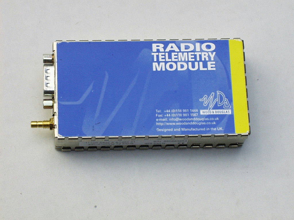
OABST450telemetry transmitter module
Primayer Limited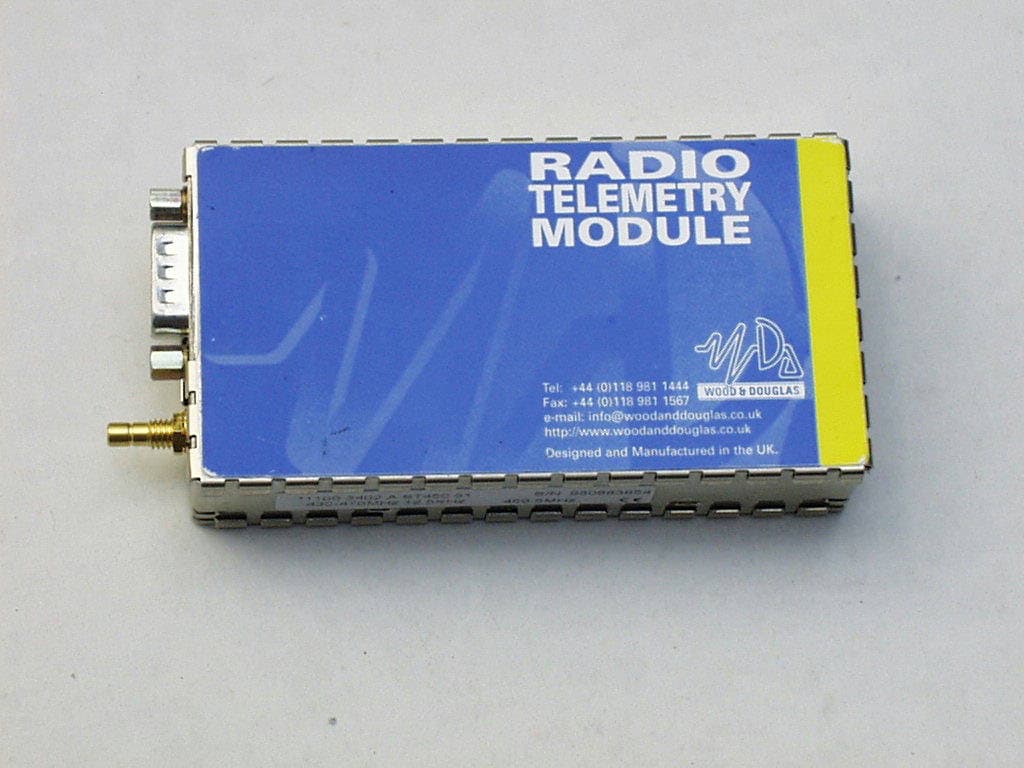
Click to zoom
Application Details
- Equipment Class
- TNB - Licensed Non-Broadcast Station Transmitter
- Date of Grant
- Feb 21, 1999
- Application Purpose
- Original Equipment
- Date of Application
- Nov 10, 1998
- Equipment Note
- telemetry transmitter module
- Frequency Range
- 430.00000000 - 470.00000000
- Company
- Primayer Limited
- Country
- United Kingdom
Documents & Files
Document Text
Text extracted from the exhibit documents filed with the FCC. Open a document above to read the original.
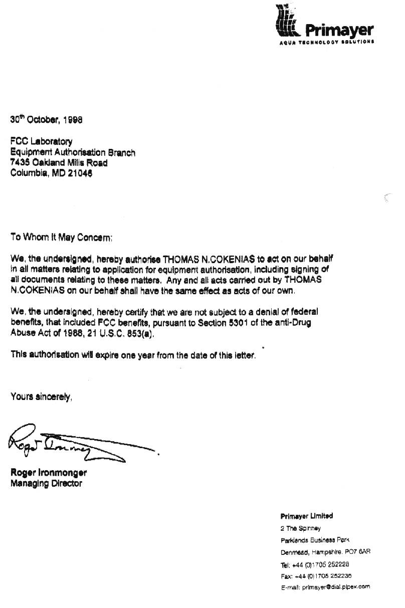
Cover Letter(s)
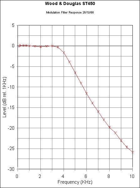
tel: 650-726-1263 fax: 650-726-1252 internet: [email protected] Thomas N. CokeniasEMC & Radio Type Approvals Test & Consulting Services for Commercial, Military, International Compliance P.O. Box 1086 El Granada, CA 94018 Clarification of Primayer Modulation as F3D Primayer's use of the ST450 is purely for analogue signals. The send the noise signal from the pipe transducer (10Hz to approx 1kHz) over the analogue radio circuit. F3D : The modulation input is an unspecified analogue signal which may vary continuously in frequency and/or amplitude. The modulation input is via pin 6 of the 9 pin connector. This is an analogue input only. Audio input up to 15Khz was applied to this port; the low pass filter prevents high frequency audio from getting to the modulator as shown by the modulation response data taken between 80 Hz and 10 kHz, with maximum deviation response at 80 Hz. The input level is such that the modulation circuit is operating just below its limiting threshold. Should the input level rise for any reason then limiting occurs and excessive frequency deviation is prevented. The low-pass filtering in the modulation circuit ensures that there are no excessive sideband levels beyond those required for normal operation. The transmitter can only work in narrowband FM mode. The modulation circuit only handles audio signals; if you throw a digital data-stream at it then all that happens is that the modulation level is made independent of the amplitude of the input and the waveform is filtered to avoid making the occupied bandwidth excessive.
ID Label/Location Info
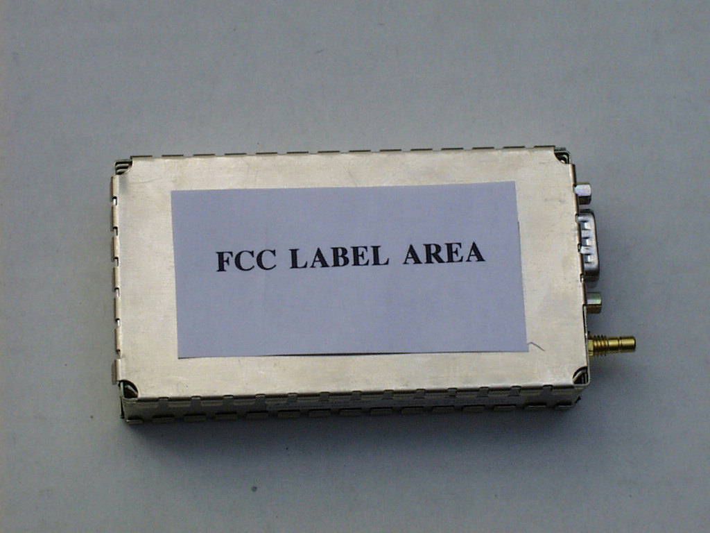
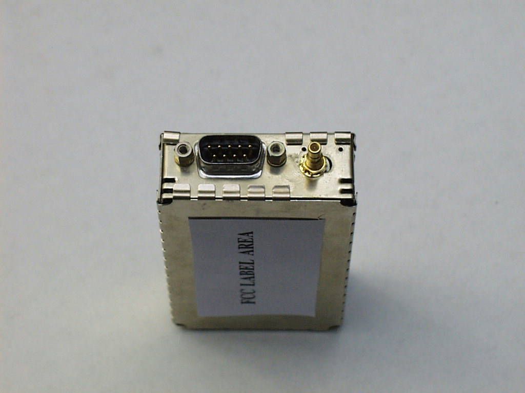
FCC ID LABEL FCC ID: OABST450 Label dimensions: 0.5” x 1” approx. Font size: 10 point Label to be located on underside of transmitter module as shown in photograph.
Test Report
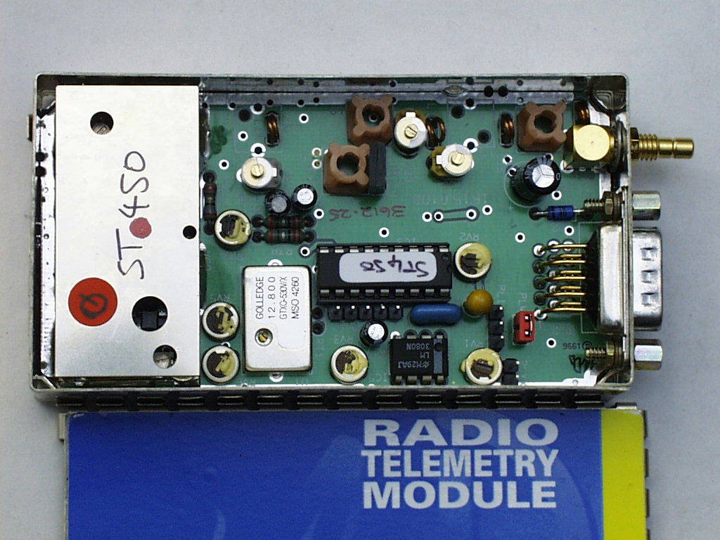
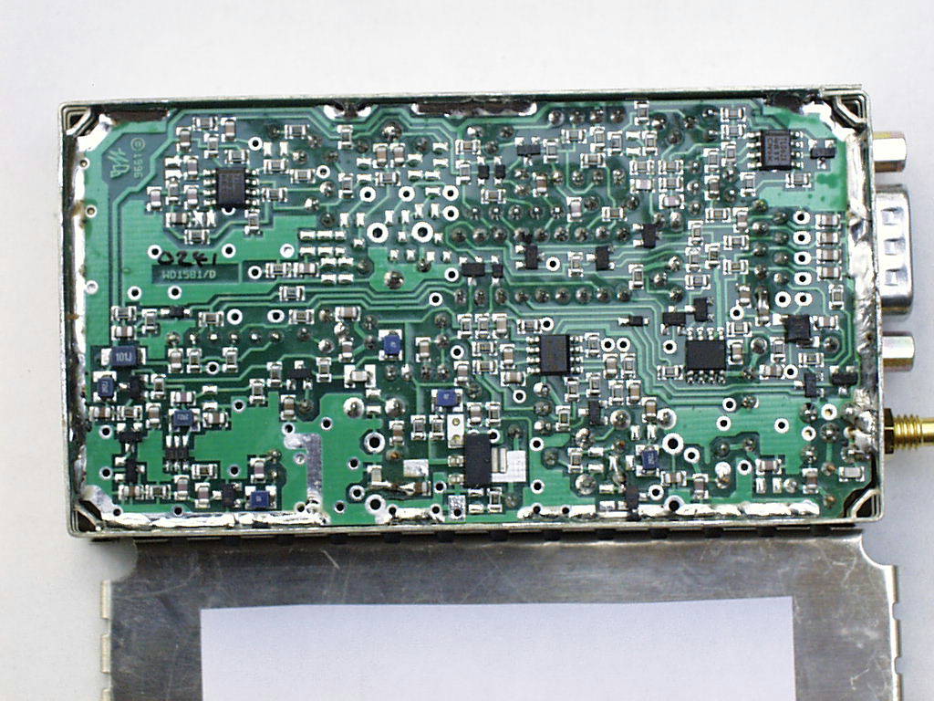
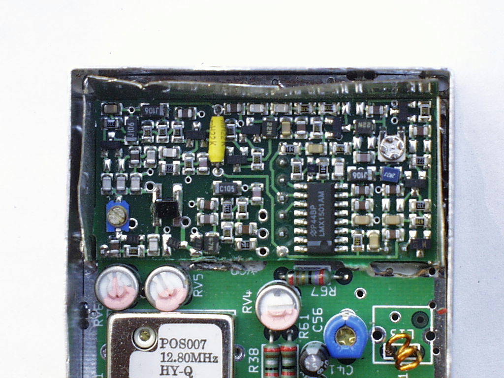
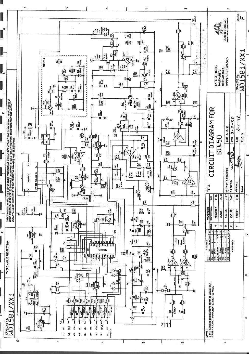
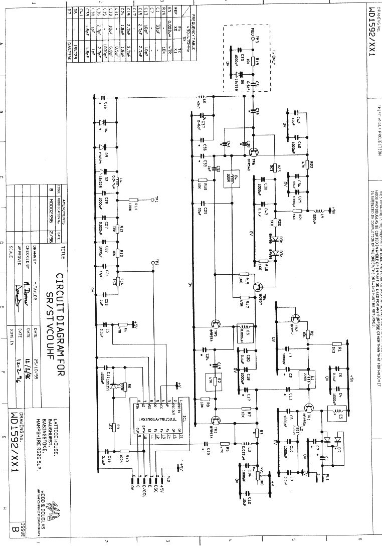
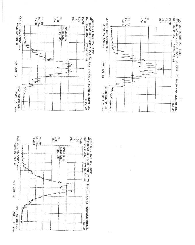
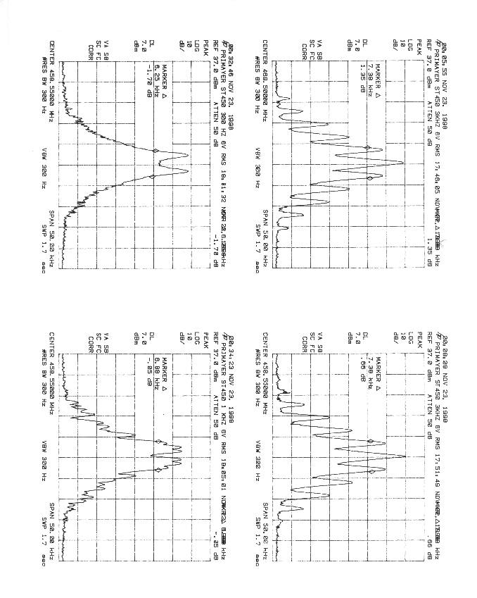
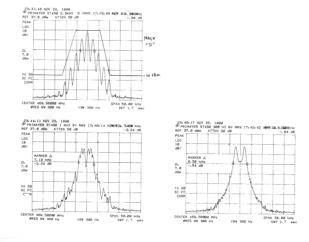
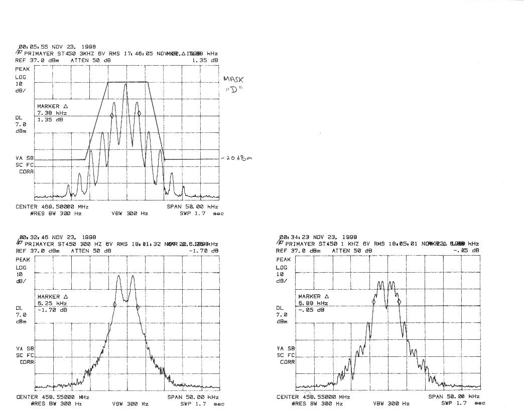
Primayer LimitedFCC ID: OABST450 1 Spectral Efficiency per Section 90.203 CERTIFICATE: Primayer Limited certifies that, per the requirements of 90.203(j)3, that the reference radio, FCC ID: OABST450, meets the spectrum efficiency channel of one voice channel bandwidth per 12.5 kHz of channel bandwidth. Furthermore, the reference device is capable of transmitting data and is capable of supporting a data rate of 4800 bits per second per 6.25 kHz of bandwidth. Channel bandwidth is calculated as the bandwidth containing 99% of the energy of the emission, or the 20 dB bandwidth. Primayer LimitedFCC ID: OABST450 2 FCC TYPE ACCEPTANCE INFORMATION The following information is in accordance with FCC Rules, 47CFR Part 2, Subpart J, sections 2.983 - 2.999. 2.983(a) Applicant:Primayer Limited. 2 The Spinney, Parklands Business Park Denmead, Hampshire ENGLAND P076AR 2.983(b) FCC ID: OABST450 2.983(c) Quantity production is planned. 2.983(d) Technical Description The ST450 is a transmitter module for incorporation in other types of devices, such as alarm panels and the like. Supply voltage is regulated, modulation input levels are limited, and the product is installed in a metal shield (can). The ST450 is comprised of two main modules: WD1581: transmitter motherboard WD 1592: VCO module Refer to document named techman.pdf for detailed technical description. (1) Types of Emissions 11K0F1D 11K0F2D 11K0F3D (2) Frequency Range Transmitter: 430-470 MHz (3) Range of Operating Power Operating power output can be adjusted from 1mW - 500 mW (4) Maximum Power Rating Primayer LimitedFCC ID: OABST450 3 Maximum output power is 500 mW (27 dBm) (5) Applied voltages and currents into the final transistor elements Determined by TR7 and IC2a for selected power output (7 VDC for 500 mW) (6) Function of Each Active Device Refer to document titled parts.pdf . (7) Complete Circuit Diagrams and Functional Block Diagram Refer to documents titled schematic.jpg and vco.jpg. (8) Instructions/Installation Manual Refer to document titled instruct.pdf . (9) Tune-up/Optimization Procedure Refer to document titled instruct.pdf . (10) Means for Frequency Stabilization A VCTCXO with internal trimmer, manufactured by Golledge Electronics Ltd., established frequency reference for the WD1592 VCO module. Refer to techman.pdf. (11) Means for Limiting Modulation IC5 and IC6 provide audio filtering to restrict the modulation bandwidth. Refer to techman.pdf for more detailed description. (11) Means for Limiting Power Power control is provided via RV4, TR7, and IC2a. Refer to techman.pdf. (11) Means for Attenuating Higher Audio Frequencies IC5 and IC6 provide audio filtering prior to the modulator circuitry. TX audio response curve is found in document titled ST450AF.jpg . (12) Description of Modulation Techniques Primayer LimitedFCC ID: OABST450 4 FM modulation. To extend the modulation bandwidth below the loop frequency of the simple phase-locked-loop in the VCO module, modulation is applied to both the VCO and the reference TCXO (a technique known as dual point modulation). Refer to techman.pdf. Primayer LimitedFCC ID: OABST450 5 2.983(e) Standard Test Conditions The transmitter was tested under the following conditions: Room Temperature: 20 - 23 ° C Relative Humidity: 35 - 50% DC Supply Voltage: 12 VDC The transmitter was aligned and tuned up according to manufacturer’s alignment procedure, prior to testing. All data presented represents the worst case parameter being measured. Section 2.983(f)Equipment Identification A drawing of the equipment identification nameplate appears in document label.doc Section 2.983(g)Photographs Photographs of the equipment, internal and external views, are in jpg format. Section 2.983 Use of Various Power Supplies Normal operation is from 9.0 - 15 VDC sources. Section 2.987 Measurement Required: Modulation Characteristics Test Set-up HP 8920A RF commo test setEUT Primayer LimitedFCC ID: OABST450 6 FM modulation deviation was measured at different frequencies at a constant input of 2 VRMS. Maximum deviation was measured for audio input at 80 Hz. FM Dev kHz v Audio Input kHz @ 2VRMS 0 1 2 3 4 5 0 0.0 3 0.10.3 25 10 Series1 Modulation Limiting: The modulation input of the radio has a design maximum input of 4 V p-p. Input voltages were varied from 0.1- 8 V p-p at five frequencies: 80 Hz, 300 Hz, 1 kHz, 2.5 kHz, and 10 kHz. FM Deviation Limiting 0 1 2 3 4 5 0.20.40.6 137 VRMS 80 Hz 300 Hz 1 kHz 2.5 kHz 10 kHz Primayer LimitedFCC ID: OABST450 7 Section 2.989 Measurement Required: Occupied Bandwidth Measurement Equipment Used: HP 8563E Spectrum Analyzer QIM “The Workhorse” low loss cable, 9 ft (loss: 0.85 dB/ft@ 26 GHz) Goldstar Audio Generator Test Set-up spectrum analyzerEUTaudio generator Data on the bandwidth occupied by this transmitter is presented in graphical form using spectrum analyzer plots. The plots depict the carrier signal modulated with 300 Hz, 1000 Hz, 2500 Hz , and 10 kHz test signals at 6 VRMS levels, well into limiting and higher than 16 dB greater than the level required to produce a modulation level of 50% at 2500 Hz. Level applied to modulation input: 6VRMS 90.209 Bandwidth limitations 90.209(d) Emission mask D: 12.5 kHz channel bandwidth equipment Any emission must be attenuated below the power (P) of the highest emission contained within the authorized bandwidth as follows: 1. On any frequency from the center of the authorized bandwidth fo to 5.625 kHz removed from fo: Zero dB 2. On any frequency removed from the center of the authorized bandwidth by a displacement frequency (fd in kHz) of more than 5.625 kHz but no more than 12.5 kHz: At least 7.27(fd-2.88 kHz) dB 3. On any frequency removed from the center of the authorized bandwidth by a displacement frequency (fd in kHz) of more than 12.5 kHz: At least 50 + 10 log(P) dB or 70 dB, whichever is the lesser attenuation. Test Results: Primayer LimitedFCC ID: OABST450 8 Refer to spectrum analyzer charts occbw1.jpg and occbw2.jpg . Section 2.…
Text truncated - open the document above for the full version.
Test Report
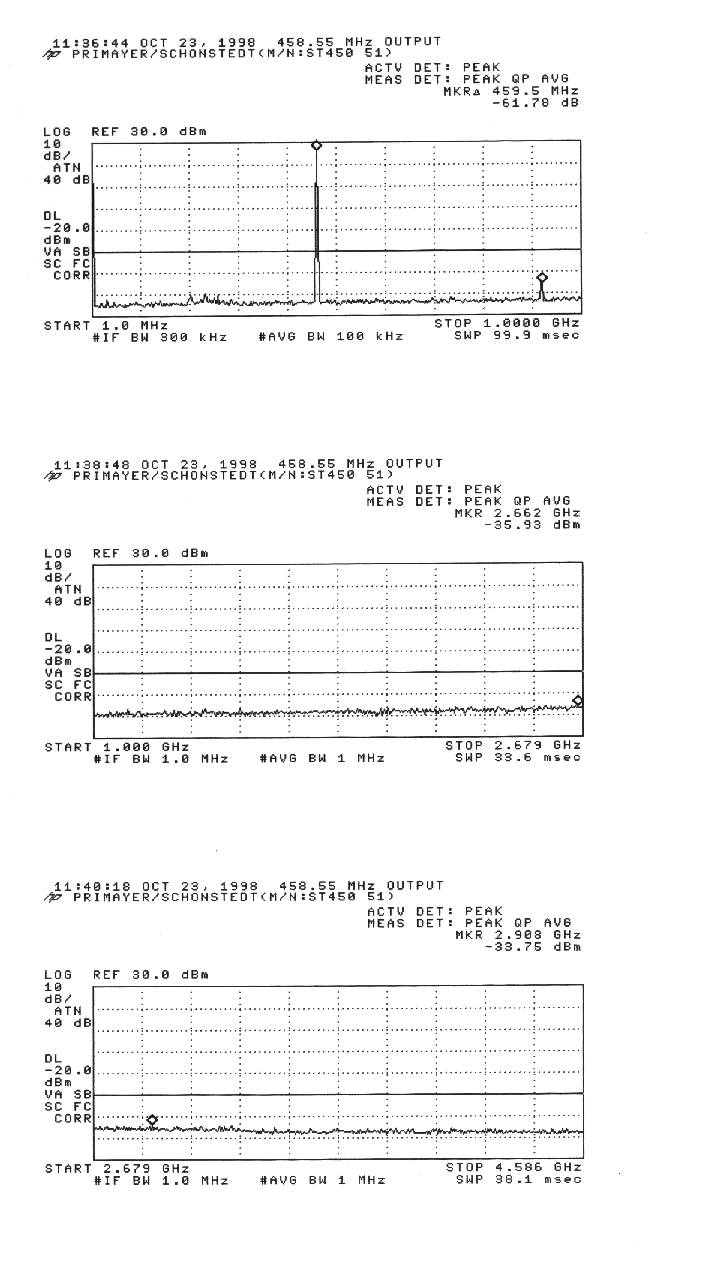
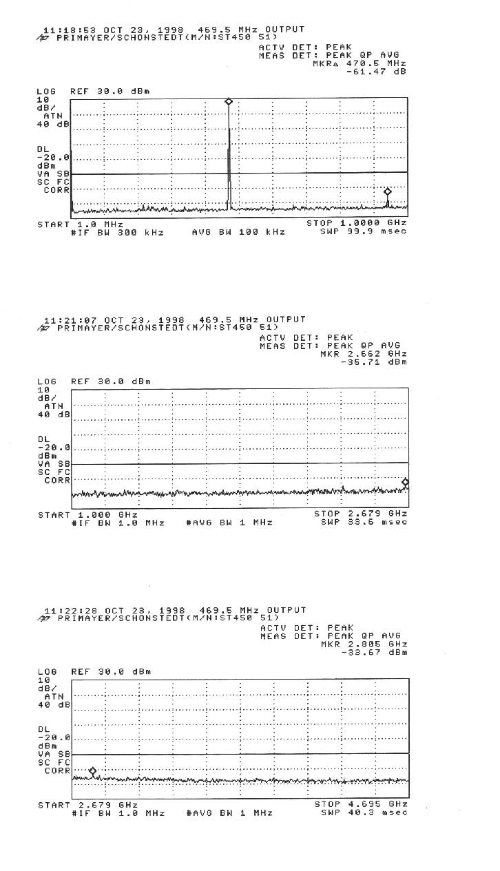
Sheet1 Radiated Harmonic Emissions (Sec. 2.993) 10/23/98 K. Corpuz Primayer Site A Radio ModuleFCC ID: OABST450 F(MHz) Level AF CL A mp Total Limit Margin (dBuV) (dB) (dB) (dB) (dBuV/m) (dBuV/m) (dBuV/m) fo=458.55 27 dBm output 917.1NF 30 42.7 0.6 -25 48.3 82.2 -33.9 1375.65NF 30 39.0 0.9 -25 44.9 82.2 -37.3 1834.2NF 32 27.0 1.5 -35 25.5 82.2 -56.7 2292.75NF 43 28.0 2.0 -35 38.0 82.2 -44.2 2751.3NF 44 30.0 2.0 -35 41.0 82.2 -41.2 3209.85NF 46 30.8 2.4 -35 44.2 82.2 -38.0 3668.5NF 39 34.1 2.8 -35 40.9 82.2 -41.3 to 4585.5 MHz: all emissions more than 30 dB below limitAttenuation at least 43+10log(Pw)dB from carrierMin Attenuation = (10log Pw + 30) - (43 + 10log Pw) = -13 dBm = .00005 wattsE = (Pw*30*G)^.5/d, at 3 meters:E = .01291 V/m = 12,925 uV/m = 82.2 dBuV/mAnalyzer: HP8593EM Antenna: EMCO 3146, 200 - 1000 MH z Antenna : ARA DRG-118/A, 1-18 GHz Page 1
Contact Information
Applicant
Roger Ironmonger(Managing Director)
Technical Contact
T.N. Cokenias ConsultingThomas N Cokenias
[email protected]650 726 1263
El Granada, California · United States
Non-Technical Contact
T.N. CokeniasThomas N Cokenias
[email protected]650 726 1263
Test Firm
Compliance Certification Services IncSteve Cheng
Technical Specifications
| # | Rule Parts | Frequency Range | Power Output | Emission | Tolerance |
|---|---|---|---|---|---|
| 1 | 90.210 | 430 MHz - 470 MHz | 500.00 mW | 11K0F3D | 2.5000000000 ppm |
Other Applications from Primayer Limited
OABCXG970001
Feb 04, 2015Eureka 3
Equipment Class
TNB - Licensed Non-Broadcast Station Transmitter