OASUCUHF1000 watt DTV UHF Transmitter
UPCOM Technologies Inc.
Click to zoom
Application Details
- Equipment Class
- TBC - Licensed Broadcast Station Transmitter
- Date of Grant
- Sep 18, 2012
- Application Purpose
- Original Equipment
- Date of Application
- Jul 02, 2012
- Equipment Note
- 1000 watt DTV UHF Transmitter
- Frequency Range
- 614.00000000 - 806.00000000
- Company
- UPCOM Technologies Inc.
- Country
- United States
Documents & Files
Document Text
Text extracted from the exhibit documents filed with the FCC. Open a document above to read the original.
Users Manual
Upcom Technologies, Inc. Page 1 Installation Operation Maintenance Troubleshooting SCA 1000 Series UHF Amplifier Upcom Technologies, Inc. San Jose, CA USA http://www.upcom.com Page 2, SCA1000 UHF Series Installation, Operation, and Maintenance Disclaimer: This equipment is to be installed only by qualified, trained professionals and in ac- cordance with local and federal codes. Failure to use a qualified professional will void all warranty coverage and may result in damage to equipment, facilities, installer and op- erator. This equipment contains RF power densities not commonly found in compact solid state amplifiers. Extreme bodily harm and / or death may result in failure to follow in- structions in this manual. Failure to comply is at the user’s own risk. Software License: User is granted a non-exclusive license to use the software as installed or as may be installed during upgrades or repairs for this amplifier only. User has the right to transfer ownership of this software as part of a sale of amplifier. User does not have the right to source code used in various embedded controllers in this system. User does not have the right to decompile or download source code or ob- ject code as installed in this system. Attempting this operation may damage the amplifier and will void any warranties. User acknowledges full software license terms, and may request the full End User Li- cense Agreement by contacting Delta RF Technology. The EULA is incorporated as part of the standard Terms and Conditions of Sale. User agrees to all terms of this license agree- ment and acknowledges consent before installing and operating this amplifier. Warranty, abbreviated: A two year manufacturer’s warranty covers this amplifier to the original purchaser and is non-transferrable. This warranty protects the end user against manufacturer’s de- fects for a period of two calendar years, as measured from the date of original shipment to end user. This warranty does not cover the end user for improper installation, installa- tion by non qualified technicians, Acts of God, intentional mis-use. Most warranty service will require the return of the entire amplifier by the end user, although arrangements may be made to defer this requirement by obtaining written pre- approval. Complete warranty details may be found at the end of this manual, or by contacting Manufacturer for up to date warranty details. This warning symbol denotes important information, or brings the user’s attention to areas of particular importance. This manual is a copyrighted work (c) 2012, Delta RF Technology, Inc. Reprint or re-use in part or whole by permission only. Revision History: 0.A - Initial Release S.Kazarian Jan 2008 0.B - Various Corrections, additional wiring diagrams, Eng/JK Mgm/SK Mar 2008 0.C - Changes for No display version of amplifier 0.D - Update for Non-verbose communications set / 4x20 LCD Display Wht/Blu 0.E - UHF Updates, Extended command set. Upcom Technologies, Inc. Page 3 Table of Contents 1. Unpacking 8 a. Verification of Contents 8 b. Damage Claims 8 2. System description 9 a. Amplifier Description: 10 i. Driver Amplifier 10 ii. RF Power Splitter 11 iii. UHF Amplifier Module 11 iv. Power Combiner 12 v. Output Directional Coupler with Universal Directional Coupler Controller (UDCC) 13 b. Mechanical Description 13 c. Control system 14 i. Main Controller 14 ii. Smart Bias Controller (SBC) 15 iii. Universal Directional Coupler Controller (UDCC) 15 iv. Ethernet Controller (optional) 15 3. Installation 16 a. Considerations 16 b. Mechanical 16 c. RF 16 d. Electrical 16 e. Serial Communications 17 f. Optional Ethernet Connection 17 4. Initial Startup and Verification 18 5. Amplifier Operation 20 a. Modes of Operation 20 b. Software Description 20 c. Error Checking 21 i. High temperature - RFPA or Heatsink 21 ii. Fan Failure - Main Heatsink 21 iii. RFPA - Current 21 iv. Power Supply - Voltage 22 v. RF Power - Forward and Reflected 22 d. Front panel operation 22 i. Splash Screen 23 ii. Default Status Display 23 iii. Main Menu 23 iv. Utility Menu 24 e. LED Display 29 6. Remote Control Operation 31 a. RS-232, RS-485 or Ethernet Connection 31 i. Serial Connection 31 ii. Ethernet Connection 31 iii. RS-485 Serial Connection 31 b. Log Error Codes 43 Page 4, SCA1000 UHF Series Installation, Operation, and Maintenance c. Rear Panel Interface Controller 45 7. Maintenance and Calibration 46 a. Detector Calibration Procedures 47 i. Forward Detector Calibration Procedure 47 ii. Reflected Detector Calibration Procedure 47 iii. Input Detector Calibration Procedure 48 b. Verify Filter Performance 49 c. Clean Heatsink and Fans 53 d. Test Safety Functions 53 i. VSWR Shutdown 53 ii. Low Input Power 54 iii. Fan Fail Detect 54 8. Troubleshooting 56 a. Problem Determination 56 b. Common toolkit required 60 c. Module Replacement 61 i. MAIN CONTROL - Moderate Repair 61 ii. DRIVER MODULE, DRV - Moderate Repair 62 iii. RF POWER SPLITTER - Advanced Repair 63 iv. RF PA MODULE - Simple Repair 64 v. 4- WAY POWER COMBINER - Advanced Repair 65 vi. OUTPUT DIRECTIONAL COUPLER - Moderate Repair 66 vii. OUTPUT RF CONNECTOR - Moderate Repair 67 viii. DC FANS - Simple Repair 67 ix. DISPLAY UNIT - Moderate Repair 69 d. Additional Repair Procedures 70 i. Biasing of RF PA Module and RF PA Driver Module 70 ii. Amplifier gain adjustment 70 9. Spare Parts List 72 i. Moderate Risk Installations 72 ii. High Risk Installations 72 iii. Module, Power Supply Repairs 72 10. Glossary 73 11. Health and Safety Warning 73 Upcom Technologies, Inc. Page 5 Page 6, SCA1000 UHF Series Installation, Operation, and Maintenance Appendices Figure 1.4 - Multi Band Filter, Top View, Cover Removed 13 Display 13 Output Switch Matrix 13 Input UDCC Input Switch Matrix 13 Filter 2 Filter 3 Filter 6 Filter 7 Filter 5 Filter 4 Filter 1 13 Output UDCC 13 Switch Control 13 ODC / UDCC Assembly with cover removed 14 1. Block Diagram - SCA1500-HF Series 74 2. Block Diagram - SCA1500-HF Series 75 3. Amplif…
Text truncated - open the document above for the full version.
Users Manual
Upcom Technologies, Inc. Page 1 Installation Operation Maintenance Troubleshooting SCA 1000 Series UHF Amplifier Upcom Technologies, Inc. San Jose, CA USA http://www.upcom.com Page 2, SCA1000 UHF Series Installation, Operation, and Maintenance Disclaimer: This equipment is to be installed only by qualified, trained professionals and in accordance with local and federal codes. Failure to use a qualified professional will void all warranty coverage and may result in damage to equipment, facilities, installer and operator. This equipment contains RF power densities not commonly found in compact solid state amplifiers. Ex- treme bodily harm and / or death may result in failure to follow instructions in this manual. Failure to comply is at the user’s own risk. The UCUHF transmitter is FCC type certified to operate only on UHF DTV channels 14-21, 25 - 31, and 39-64. Operation on other channels than those specified requires the use of an additional low pass filter. Please contact UPCOM for further information. Software License: User is granted a non-exclusive license to use the software as installed or as may be installed during upgrades or repairs for this amplifier only. User has the right to transfer ownership of this software as part of a sale of amplifier. User does not have the right to source code used in various embedded controllers in this system. User does not have the right to decompile or download source code or object code as installed in this system. At- tempting this operation may damage the amplifier and will void any warranties. User acknowledges full software license terms, and may request the full End User License Agreement by contacting Delta RF Technology. The EULA is incorporated as part of the standard Terms and Conditions of Sale. User agrees to all terms of this license agreement and acknowledges consent before installing and operating this amplifier. Warranty, abbreviated: A two year manufacturer’s warranty covers this amplifier to the original purchaser and is non-transferrable. This warranty protects the end user against manufacturer’s defects for a period of two calendar years, as mea- sured from the date of original shipment to end user. This warranty does not cover the end user for improper installation, installation by non qualified technicians, Acts of God, intentional mis-use. Most warranty service will require the return of the entire amplifier by the end user, although arrangements may be made to defer this requirement by obtaining written pre-approval. Complete warranty details may be found at the end of this manual, or by contacting Manufacturer for up to date warranty details. This warning symbol denotes important information, or brings the user’s attention to areas of particular importance. This manual is a copyrighted work (c) 2012, Delta RF Technology, Inc. Reprint or re-use in part or whole by permission only. Revision History: 0.A - Initial Release S.Kazarian Jan 2008 0.B - Various Corrections, additional wiring diagrams, Eng/JK Mgm/SK Mar 2008 0.C - Changes for No display version of amplifier 0.D - Update for Non-verbose communications set / 4x20 LCD Display Wht/Blu 0.E - UHF Updates, Extended command set. Upcom Technologies, Inc. Page 3 Table of Contents 1. Unpacking 8 a. Verification of Contents 8 b. Damage Claims 8 2. System description 9 a. Amplifier Description: 10 i. Driver Amplifier 10 ii. RF Power Splitter 11 iii. UHF Amplifier Module 11 iv. Power Combiner 12 v. Output Directional Coupler with Universal Directional Coupler Controller (UDCC) 13 b. Mechanical Description 13 c. Control system 14 i. Main Controller 14 ii. Smart Bias Controller (SBC) 15 iii. Universal Directional Coupler Controller (UDCC) 15 iv. Ethernet Controller (optional) 15 3. Installation 16 a. Considerations 16 b. Mechanical 16 c. RF 16 d. Electrical 16 e. Serial Communications 17 f. Optional Ethernet Connection 17 4. Initial Startup and Verification 18 5. Amplifier Operation 20 a. Modes of Operation 20 b. Software Description 20 c. Error Checking 21 i. High temperature - RFPA or Heatsink 21 ii. Fan Failure - Main Heatsink 21 iii. RFPA - Current 21 iv. Power Supply - Voltage 22 v. RF Power - Forward and Reflected 22 d. Front panel operation 22 i. Splash Screen 23 ii. Default Status Display 23 iii. Main Menu 23 iv. Utility Menu 24 e. LED Display 29 6. Remote Control Operation 31 a. RS-232, RS-485 or Ethernet Connection 31 i. Serial Connection 31 ii. Ethernet Connection 31 iii. RS-485 Serial Connection 31 b. Log Error Codes 43 Page 4, SCA1000 UHF Series Installation, Operation, and Maintenance c. Rear Panel Interface Controller 45 7. Maintenance and Calibration 46 a. Detector Calibration Procedures 47 i. Forward Detector Calibration Procedure 47 ii. Reflected Detector Calibration Procedure 47 iii. Input Detector Calibration Procedure 48 b. Verify Filter Performance 49 c. Clean Heatsink and Fans 53 d. Test Safety Functions 53 i. VSWR Shutdown 53 ii. Low Input Power 54 iii. Fan Fail Detect 54 8. Troubleshooting 56 a. Problem Determination 56 b. Common toolkit required 60 c. Module Replacement 61 i. MAIN CONTROL - Moderate Repair 61 ii. DRIVER MODULE, DRV - Moderate Repair 62 iii. RF POWER SPLITTER - Advanced Repair 63 iv. RF PA MODULE - Simple Repair 64 v. 4- WAY POWER COMBINER - Advanced Repair 65 vi. OUTPUT DIRECTIONAL COUPLER - Moderate Repair 66 vii. OUTPUT RF CONNECTOR - Moderate Repair 67 viii. DC FANS - Simple Repair 67 ix. DISPLAY UNIT - Moderate Repair 69 d. Additional Repair Procedures 70 i. Biasing of RF PA Module and RF PA Driver Module 70 ii. Amplifier gain adjustment 70 9. Spare Parts List 72 i. Moderate Risk Installations 72 ii. High Risk Installations 72 iii. Module, Power Supply Repairs 72 10. Glossary 73 11. Health and Safety Warning 73 Upcom Technologies, Inc. Page 5 Page 6, SCA1000 UHF Series Installation, Operation, and Maintenance Appendices Figure 1.4 - Multi Band Filter, Top View, Cover Removed 13 Display 13 Output Switch Matrix 13 Input UDCC Input Switc…
Text truncated - open the document above for the full version.
Block Diagram
Document Title Date - RevisionDate - Revision Part Number 1000W 470 - 860 MHz UHF Digital Television Amplifier SCA1000-UHF-A series Jan 2012 - A Disclaimer: This information is freely provided to our customers for reference purposes only. Many factors affect performance, including signal source integrity, proper wiring and connections, mechanical mounting and heatsinking. Please consult the factory prior to making a choice if you are unsure about integration. Factory warranty does not apply to improperly installed and / or operated amplifiers. This information applies only to Delta RF Technology and Silicon Valley Amplifier manufactured amplifiers, splitters, combiners, and filters. (c) 2010 Delta RF Technology 1 / 1 Page 4-way in phase combiner. 1100W power handling capability 4-way in phase splitter. 20W power handling capability. Input D.C. Optional LCD Front Panel Display Output D.C. FWD / REF ODC^2 Broadband Power Detector / Emergency Stop RF Out -0.60dB -0.40dB to -0.70dB -0.65dB -0.30dB to -0.80dB -2.0dB 22.3W +43.5dBm 10mW +9.5dBm 1050W +60.25dBm 1000W +60.00dBm -0.25dB -0.15dB to -0.30dB Mask Filter +5V SW PS P1000-UHF-20 309W +54.9dBm 20dB 4.9W +36.9dBm 50VDC/20A P1000-UHF-20 309W +54.9dBm 20dB 4.9W +36.9dBm 50VDC/20A P1000-UHF-20 309W +54.9dBm 20dB 4.9W +36.9dBm 50VDC/20A 20dB P1000-UHF-20 309W +54.9dBm 18dB 4.9W +36.9dBm 50VDC/20A 4-way in phase splitter. 20W -0.40dB to -0.70dB 4.9W4.9W +36.9dBm 4.9W4.9W +36.9dBm 4.9W4.9W +36.9dBm 4.9W4.9W +36.9dBm 4-way in phase combiner. 1100W 4-way in phase combiner. 1100W -0.30dB to -0.80dB RS-232 Serial PortRS-232 Serial Port Optional Ethernet Interface 10 Base T or USB Optional RS-485/RS-422 Controller Legend Vsup (+48VDC) RF Path Data Bus High Speed Analog Main Power Supply 185 - 264VAC Input, 1 Ph +48VDC Output 6.0-kW Output SCA Series Controller 48VDC/1.5A x 2 PA30-UHF-36 36dB 5.6mW +7.5dBm 50VDC/2A #5949 #6024 (2) #5988 (4) #5823 - #5986 #5823 - #5986#4489 #5991 Includes DC and Driver #5300 #5950 1000W +60.00dBm ATSC Exciter ASI Input
Block Diagram
Document Title Date - RevisionDate - Revision Part Number 1000W 470 - 860 MHz UHF Digital Television Amplifier SCA1000-UHF-A series Jan 2012 - A Disclaimer: This information is freely provided to our customers for reference purposes only. Many factors affect performance, including signal source integrity, proper wiring and connections, mechanical mounting and heatsinking. Please consult the factory prior to making a choice if you are unsure about integration. Factory warranty does not apply to improperly installed and / or operated amplifiers. This information applies only to Delta RF Technology and Silicon Valley Amplifier manufactured amplifiers, splitters, combiners, and filters. (c) 2010 Delta RF Technology 1 / 1 Page 4-way in phase combiner. 1100W power handling capability 4-way in phase splitter. 20W power handling capability. Input D.C. Optional LCD Front Panel Display Output D.C. FWD / REF ODC^2 Broadband Power Detector / Emergency Stop RF Out -0.60dB -0.40dB to -0.70dB -0.65dB -0.30dB to -0.80dB -2.0dB 22.3W +43.5dBm 10mW +9.5dBm 1050W +60.25dBm 1000W +60.00dBm -0.25dB -0.15dB to -0.30dB Mask Filter +5V SW PS P1000-UHF-20 309W +54.9dBm 20dB 4.9W +36.9dBm 50VDC/20A P1000-UHF-20 309W +54.9dBm 20dB 4.9W +36.9dBm 50VDC/20A P1000-UHF-20 309W +54.9dBm 20dB 4.9W +36.9dBm 50VDC/20A 20dB P1000-UHF-20 309W +54.9dBm 18dB 4.9W +36.9dBm 50VDC/20A 4-way in phase splitter. 20W -0.40dB to -0.70dB 4.9W4.9W +36.9dBm 4.9W4.9W +36.9dBm 4.9W4.9W +36.9dBm 4.9W4.9W +36.9dBm 4-way in phase combiner. 1100W 4-way in phase combiner. 1100W -0.30dB to -0.80dB RS-232 Serial PortRS-232 Serial Port Optional Ethernet Interface 10 Base T or USB Optional RS-485/RS-422 Controller Legend Vsup (+48VDC) RF Path Data Bus High Speed Analog Main Power Supply 185 - 264VAC Input, 1 Ph +48VDC Output 6.0-kW Output SCA Series Controller 48VDC/1.5A x 2 PA30-UHF-36 36dB 5.6mW +7.5dBm 50VDC/2A #5949 #6024 (2) #5988 (4) #5823 - #5986 #5823 - #5986#4489 #5991 Includes DC and Driver #5300 #5950 1000W +60.00dBm ATSC Exciter ASI Input
Cover Letter(s)
1 CONFIDENTIALITY REQUEST LETTER UC-UHF TRANSMITTER TECHNICAL DATA Pursuant to FCC 0.457(d) and 0.459 of the FCC Rules long-term confidentiality is requested due to the fact that the applicant, UpCom, considers certain information to be submitted as trade secret information. Specifically, the schematics and parts lists submitted as exhibits for type certification for the above transmitter are not normally available to anyone outside of company employees. The specific files needing confidentiality are identified as: Exciter Schematics.pdf PA Combined Schematics file.pdf Exciter Parts List.pdf SCA PA parts list.pdf The company has gone to great expense to develop the equipment and they could be financially harmed if another competitor were to copy the products using the schematics and parts list information and make them available for sale. The parts list and schematic information contained within the exhibits submitted with this type certification application is not supplied with customer documentation. Because of the nature of the schematics and parts lists, redacted documents are not possible. At a minimum, a period of 5 years is necessary for confidentiality for these documents. Regards, UC-‐UHF
Cover Letter(s)
July 3, 2012 Federal Communications Commission OET Laboratory Division 445 12 th St. SW Washington, DC 20554 Dear Sir, Provided on behalf of Upcom Technologies, Inc. this letter will provide additional information to the exhibits filed for the UPCOM UC-UHF DTV transmitter type certification for the UHF TV frequency range. The documentation package for this submission does not include filtering of harmonics related to the GPS band frequencies as indicated in FCC 74. 794 (b) (1). Thus it is recognized that the present submission package will not be sufficient for operation on channels 22-24, 32-38, and 65-69. Sincerely, President Greg Best Consulting, Inc. 9223 N. Manning Ave. Kansas City, MO 64157 816-792-2913
Cover Letter(s)
September 6, 2012 CONFIDENTIALITY REQUEST LETTER UC-UHF TRANSMITTER TECHNICAL DATA CONFIDENTIALITY REQUEST Pursuant to FCC 0.457(d) and 0.459 of the FCC Rules long-term confidentiality is requested due to the fact that the applicant, UpCom, considers certain information to be submitted as trade secret information. Specifically, the schematics and parts lists submitted as exhibits for type certification for the above transmitter are not normally available to anyone outside of company employees. The specific files needing confidentiality are identified as: Exciter Schematics.pdf PA Combined Schematics file.pdf Exciter Parts List.pdf SCA PA parts list.pdf The company has gone to great expense to develop the equipment and they could be financially harmed if another competitor were to copy the products using the schematics and parts list information and make them available for sale. The parts list and schematic information contained within the exhibits submitted with this type certification application is not supplied with customer documentation. Because of the nature of the schematics and parts lists, redacted documents are not possible. At a minimum, a period of 5 years is necessary for confidentiality for these documents. Regards, Greg Best Consulting, Inc. 9223 N. Manning Ave. Kansas City, MO 64157 816-792-2913
External Photos
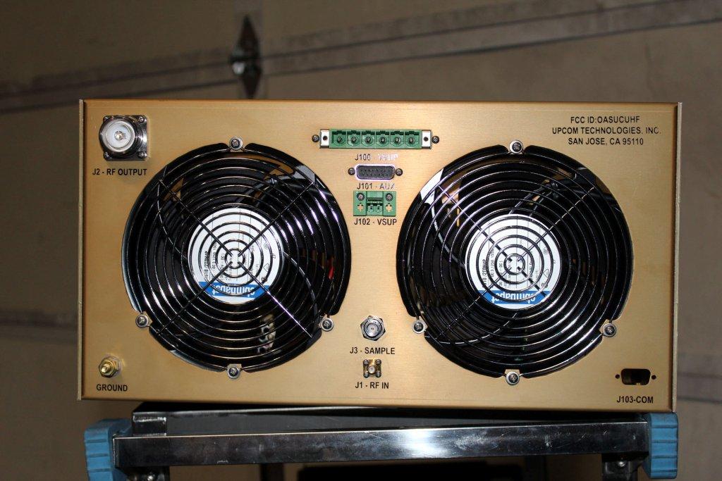
EXTERNAL CONSTRUCTION PHOTOS TOP AND FRONT VIEW OF TRANSMITTER EXCITER UNIT BOTTOM VIEW OF TRANSMITTER EXCITER UNIT (This photo also shows the right side of the exciter unit). REAR VIEW OF TRANSMITTER EXCITER UNIT LEFT TOP VIEW OF TRANSMITTER EXCITER UNIT (The left side view of the unit is the same with or without the top cover). TOP VIEW OF TRANSMITTER AMPLIFIER UNIT REAR VIEW OF AMPLIFIER UNIT BOTTOM VIEW OF AMPLIFIER UNIT RIGHT SIDE VIEW OF AMPLIFIER UNIT LEFT SIDE VIEW OF AMPLIFIER UNIT EMISSION MASK FILTER VIEW
ID Label/Location Info
J100 - VSUP J2 - RF OUTPUT GROUND J1 - RF IN J103-COM J3 - SAMPLE J101 - AUX J102 - VSUP FCC ID:OASUCUHF UPCOM TECHNOLOGIES, INC. SAN JOSE, CA 95110 17.00” 3.00” 0.85” 8.75”
Internal Photos
INTERNAL CONSTRUCTION PHOTOS FRONT VIEW OF EXCITER UNIT TOP VIEW OF EXCITER UNIT FROM RIGHT TOP VIEW OF EXCITER UNIT FROM LEFT REAR VIEW OF EXCITER UNIT VIEW OF FRONT OF TRANSMITTER AMPLIFIER UNIT VIEW OF TOP OF TRANSMITTER AMPLIFIER UNIT WITHOUT COVER VIEW OF BOTTOM OF TRANSMITTER AMPLIFIER UNIT WITHOUT COVER VIEW OF REAR OF TRANSMITTER AMPLIFIER UNIT WITHOUT COVER
Operational Description
OPERATIONAL DESCRIPTION OF UPCOM UC-‐UHF TRANSMITTER The UPCOM model UC-‐UHF model transmitter is composed of multiple modules including the final emission mask filter which is externally mounted and connected to the transmitter via transmission line. The transmitter is composed of one or more exciters, a control unit, one or more amplifiers operating in parallel, splitter and combiner unit, cooling system, and output filtering. The exciter unit accepts the transport stream input signal and converts this to an ATSC RF modulated signal. The exciter includes signal processing to improve transmitter linearity performance and frequency response as well as compensating for frequency response issues in the transmission system beyond the transmitter before it reaches the antenna. If dual exciters are used, an exciter switcher is used to select which exciter is routed to the transmitter. After the exciter, the signal is directed to one or more amplifiers operating in parallel. Here the modulated ATSC signal is amplified. A combiner is used to add the signal from each of the amplifiers and then the combined signal is routed to the emission mask filtering. The signal is applied to an externally mounted emission mask filter to eliminate adjacent channel radiation and to provide FCC emission mask compliance. The control unit interfaces with each subsystem within the transmitter and provides monitoring of each function, implements automatic power control, communicates with any remote control system, and provides fault protection for the transmitter. The cooling system contains the fans necessary to properly cool all components within the transmitter and interfaces with the control system for proper operation.
Test Report
UPCOM Technologies Inc. UC-UHF TEST RESULTS AND MEASUREMENTS 1 UC-UHF TRANSMITTER TECHNICAL REPORT The following information is provided to support the technical performance of the UC-UHF DTV transmitter. The information is supplied for broadcast TV service according to applicable portions of Part 74 of the FCC Rules. The information in this report is provided in support of verification that the transmitter meets the appropriate requirements. Measurements outlined below were recorded of spectrum and other data to demonstrate compliance. 1. Power Output Measurements 2. Frequency stability tests versus AC input voltage and temperature 3. Measurements to demonstrate the transmitter meets the DTV emission mask as specified in FCC Rule 74.794. 4. Measurement of cabinet radiation for spurs and harmonics as specified in FCC Rule 2.1053 and Rule 2.1057 Measurements for power output and emission mask compliance were conducted at power output levels of both 1000 watts and 250 watts which matches the power range for the type certification range of operation. The test equipment used for the measurements is listed at the end of this document. UPCOM Technologies Inc. UC-UHF TEST RESULTS AND MEASUREMENTS 2 TABLE OF CONTENTS RF Output Power Measurement................................................................................. 4 Emission Mask Compliance...................................................................................... 5 Frequency Stability................................................................................................. 11 Cabinet Radiation................................................................................................... 13 Low Power Operation ............................................................................................. 17 Test Equipment List................................................................................................. 22 UPCOM Technologies Inc. UC-UHF TEST RESULTS AND MEAS UREMENTS 3 Temp Chamber Note: The attenuation factor of attenuators and spl itter was determined to be 47.9 dB FIGURE 1 — TEST EQUIPMENT CONFIGURATION Exciter Transmitter PA Pre-Filter Coupler Emission Mask Filter Attenuators Bandstop Filter R & S ETL Power Meter High Pass Filter Splitter 8 GHz Spectrum Analyzer Variac Post-Filter Coupler UPCOM Technologies Inc. UC-UHF TEST RESULTS AND MEASUREMENTS 4 RF Power Output Measurements The equipment was configured as shown in Figure 1. The attenuation factor through the attenuators was calibrated at the channel center frequency of the channel 31 DTV signal of 575 MHz. Average power was read on the Agilent HP437B Power Meter. Measurement Of Nominal Transmitter Power The transmitter was energized at nominal power in the test configuration above and the power was read on the HP437B Power Meter through a calibrated 47.9 dB attenuator. The indicated reading is shown below. Figure 2—Power Meter Reading at Nominal Transmitter Power Calculation of Output Power: An offset of 47.9 dB, equal to the attenuator and splitter loss plus the calibrated cable was entered into the HP437B to allow direct display of output power in watts average power. With this condition, measured transmitter final amplifier voltage is 51.5 VDC and final amplifier current is 75.7 Amps. UPCOM Technologies Inc. UC-UHF TEST RESULTS AND MEASUREMENTS 5 Emission Mask Compliance To determine emission mask compliance, the test equipment configuration shown in Figure 1 was used. For frequency measurements below 3 GHz, the R & S ETL spectrum analyzer was used and for frequencies above 3 GHz, the Avantest R3162 was used. The transmitter tested for compliance with the emission mask as specified in FCC rule 74.794. The IEEE 2008-1631 Recommended Practice On 8-VSB Digital Television Transmission Compliance Measurement was used as the test measurement methodology. The first part of the tests measured the adjacent channel emission and the second part of the tests measured the harmonic and spurious energy. The transmitter was energized at 1000 watts on Channel 31 (center frequency of 575 MHz) as calculated by the insertion loss of the attenuator and a reference was established on the spectrum analyzer (using the channel power measurement mode). The bandstop filter frequency response was determined using a spectrum analyzer and tracking generator combination. The insertion loss at the center of each of the twelve 500 kHz segments either side of the main channel was tabulated. The bandstop filter response is shown as Plot 1. The attenuation has been tabulated in the next section with the spreadsheet of measured emission values. Figure 3 Bandstop Filter Response UPCOM Technologies Inc. UC-UHF TEST RESULTS AND MEASUREMENTS 6 The noise floor of the spectrum analyzer was found and from that the minimum RF sample level was determined (assuming the transmitter exactly met the emission mask requirements identified in the FCC rules). The actual RF sample level was well above the required minimum RF sample so plenty of margin was available with the test configuration used. The transmitter was energized at 1000 Watts and optimized for linearity. The 6 MHz DTV channel power was first measured for the channel 31 signal. Then the twelve 500 kHz segments on both sides of the Channel 31 signal were measured. The closest four 500 kHz segments on either side of the Channel 31 signal were measured without the use of the bandstop filter because those signals were above the noise floor of the spectrum analyzer with the existing spectrum analyzer setting. The bandstop filter was inserted in the path according to the set-up in Figure 1. The spectrum analyzer attenuation setting was reduced and the remaining 500 kHz segments on each side of Channel 31 were measured and the data was recorded in the emission mask spreadsheet provided on the next page. The measured values were corrected for proximity to the noise floor first and then for the bandstop filter insertion loss. The tra…
Text truncated - open the document above for the full version.
Contact Information
Applicant
Ricardo Dias(President)
Technical Contact
Greg Best Consulting, Inc.Greg Best
[email protected]816-792-2913
9223 N. Manning Avenue · Kansas City, Missouri
Technical Specifications
| # | Rule Parts | Frequency Range | Power Output | Emission | Tolerance |
|---|---|---|---|---|---|
| 2 | 74 | 614 MHz - 806 MHz | 1000 W | 6M00K1D | 1000 Hz |