OB2-STDREMPortable Remote Controlled Scoreboard
ScoreTronics, Inc.
Click to zoom
Application Details
- Equipment Class
- DSC - Part 15 Security/Remote Control Transmitter
- Date of Grant
- Apr 13, 1999
- Application Purpose
- Original Equipment
- Date of Application
- Dec 16, 1998
- Equipment Note
- Portable Remote Controlled Scoreboard
- Frequency Range
- 314.80000000 - 315.20000000
- Company
- ScoreTronics, Inc.
- Country
- United States
Documents & Files
Document Text
Text extracted from the exhibit documents filed with the FCC. Open a document above to read the original.
Users Manual
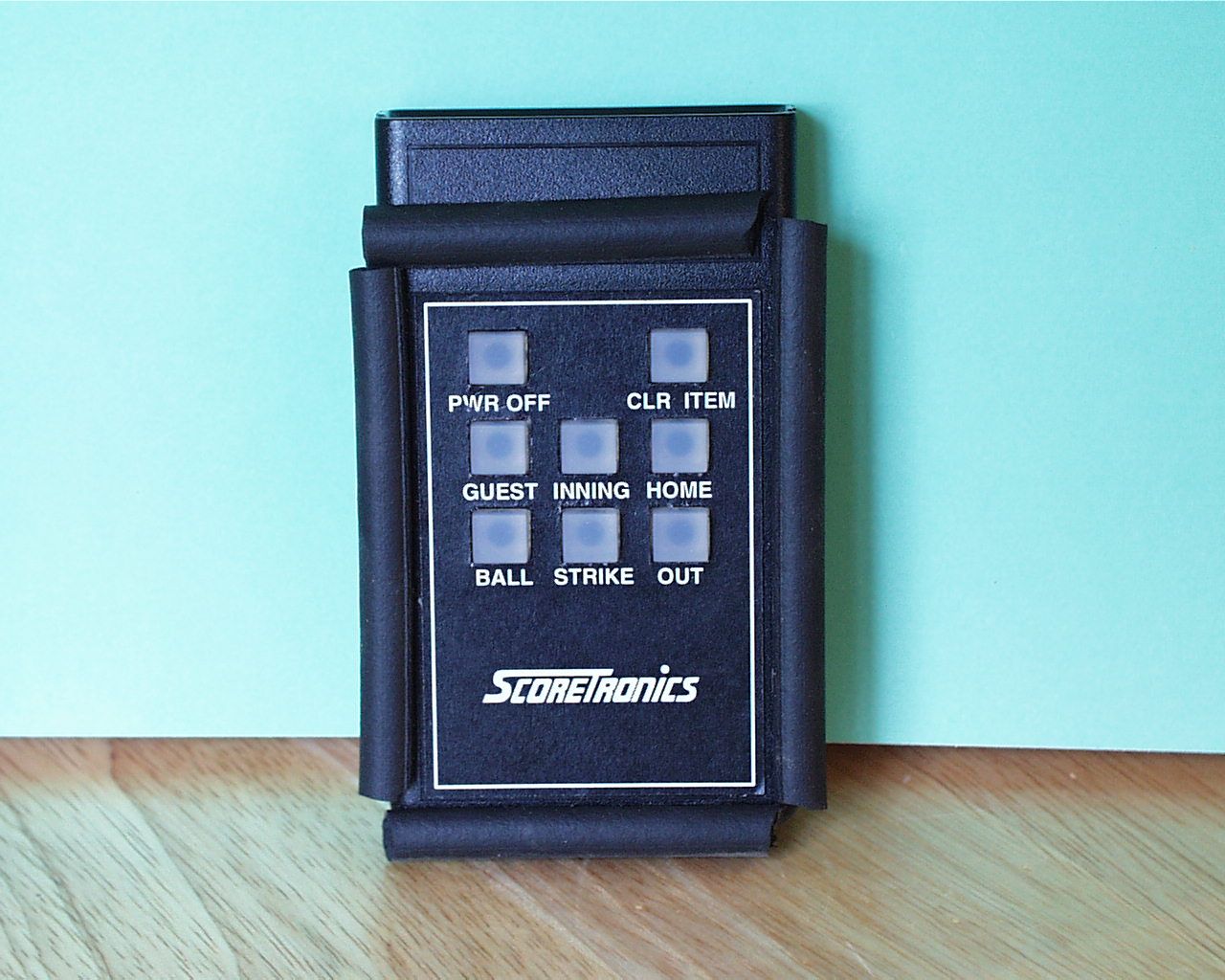
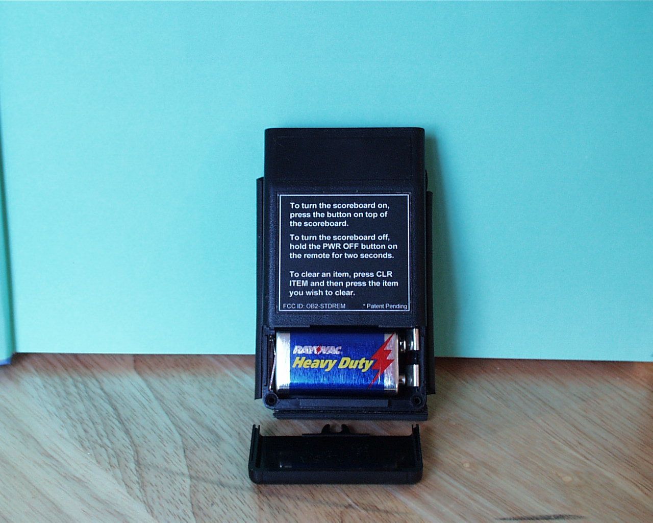
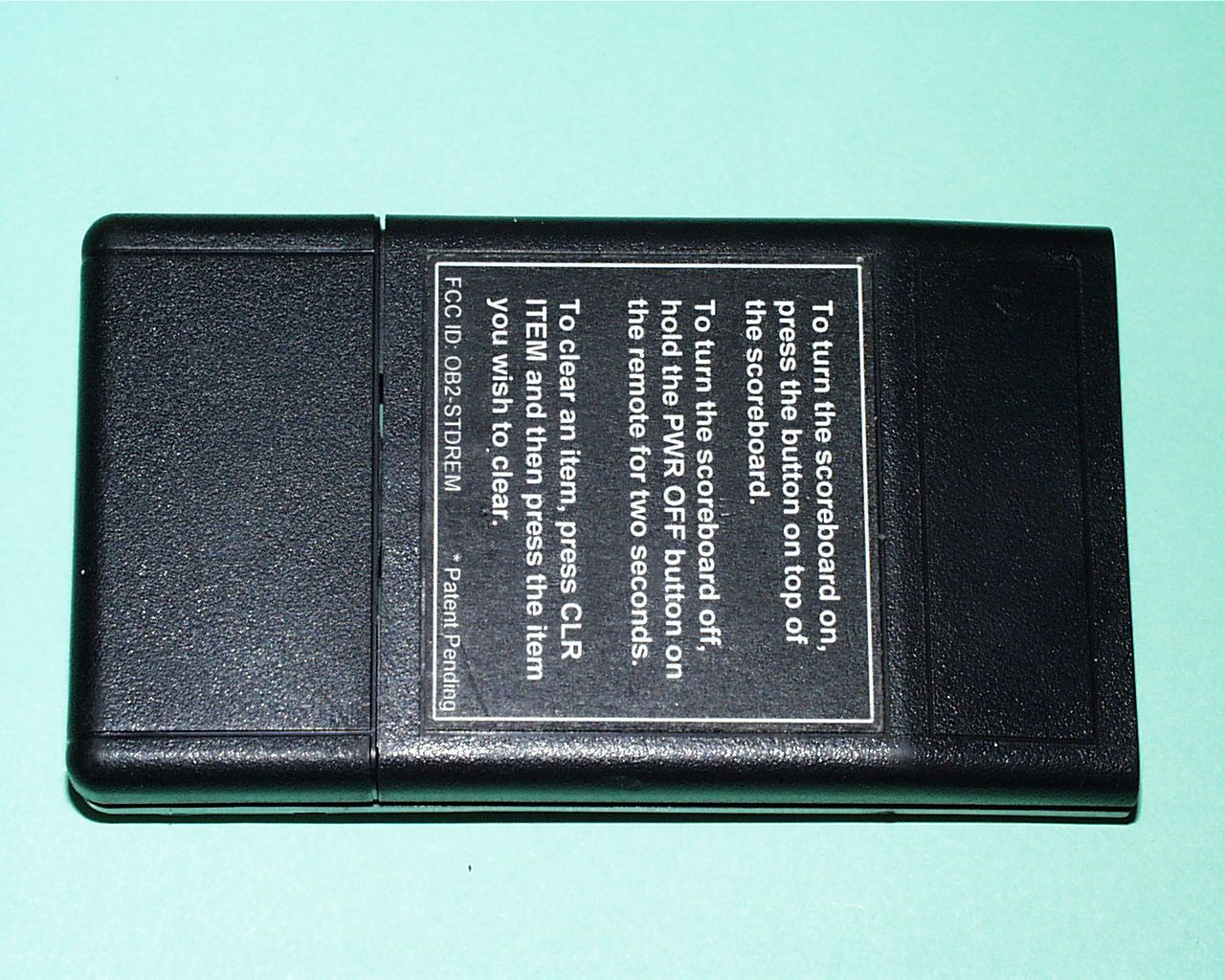
ScoreTronics, Inc., 1110 Jorie Blvd., Suite 104, Oak Brook, IL 60523 Phone 630-571-1970 www.scoretronics.com *Patent Pending PBA-4 Portable Baseball/Softball Scoreboard Owner’s Manual ScoreTronics PBA-4 Portable Baseball/Softball Owner’s Manual Page 1 ScoreTronics, Inc., 1110 Jorie Blvd., Suite 104, Oak Brook, IL 60523 Phone 630-571-1970 www.scoretronics.com Turning the Scoreboard On To turn the scoreboard on, press the green button on the top of the scoreboard.The remote control is always ready for use. It has no power switch. Power On Self Check When the scoreboard first turns on, it will go through a self check. All digits anddots will turn ON for two seconds, then turn OFF for two seconds, and then resetto zero score, first inning, no balls, strikes or outs. If the batteries are sensed low,the scores will flash “LO” “BA” at the end of the self check. Turning the Scoreboard Off To turn the scoreboard off, press and hold down the PWR OFF button on theremote control for TWO SECONDS. The scoreboard will also automatically turnoff after 30 minutes of non-use. The scores will display “PO” “PO” for twoseconds to indicate that it is powering down. Setting Up the Scoreboard at the Field Slide the scoreboard over the installed steel pipe. The pipe will insert about nineinches up into the scoreboard. Then rotate the scoreboard until the locating pininside the unit drops into the notch in the top of the pipe. This will hold thescoreboard facing the proper direction.Your scoreboard is designed to withstand occasional rain showers. However, it isintended to be stored away when not in use and not be permanently mountedoutdoors. The materials used in your scoreboard will age prematurely if thescoreboard is continuously exposed to sunlight when not in use. Using the Scoreboard To advance the score, inning, balls, strikes or outs, simply press thecorresponding button on the remote control. ScoreTronics PBA-4 Portable Baseball/Softball Owner’s Manual Page 2 ScoreTronics, Inc., 1110 Jorie Blvd., Suite 104, Oak Brook, IL 60523 Phone 630-571-1970 www.scoretronics.com The balls and strikes will automatically return to zero when you advance past thethird ball or second strike. The outs will return to zero when advancing past thesecond out. The inning will indicate “0” when advancing to inning 10 and showthe last digit for innings above 10.To clear any item, press the CLR ITEM on the remote control, then press the itemyou wish to clear. When cleared, the scores, balls, strikes, or outs will reset to 0and the inning will reset to 1.If the batteries are getting low, the scores will momentarily flash “LO” “BA” whenthe scores or inning are changed. The batteries should be replaced soon whenthis indication occurs to maintain reliable operation. Radio System The range of the remote control is over 500 feet in open field conditions (noobstructions). However, obstructions such as fences and people, and outsideinterference will reduce this range.Radio dead spots (a spot where the scoreboard won’t respond to the remote) canoccur in some fields. This is normal. The usual solution is to step a few feet inany direction away from that spot. Batteries The scoreboard uses 16 AA alkaline batteries which are included and pre-installed in your unit. The expected life of these batteries under normal conditionsis 500 hours (200 2-1/2 hour games).The unit has a low battery detection system that will flash “LO” “BA” whenchanging the score or inning if the batteries are low. However, to preventinconvenience to the users, it is best to replace the batteries every one or twoseasons.To replace the batteries in the scoreboard, the front panel must be removed.Using a Phillips screwdriver, remove the screws around the edge of the frontpanel and lift out the front panel. The batteries are in two holders just below thescore digits. Observe the polarity markings in the holders when installing the newbatteries. Name brand batteries are recommended. Before reinstalling the frontpanel, clean the inside of the panel with a soft cloth to remove any accumulated ScoreTronics PBA-4 Portable Baseball/Softball Owner’s Manual Page 3 ScoreTronics, Inc., 1110 Jorie Blvd., Suite 104, Oak Brook, IL 60523 Phone 630-571-1970 www.scoretronics.com dust. Use caution when tightening the screws when re-installing the front panel,as they can be stripped by overtightening.The remote control uses a 9 volt alkaline battery which is also included and pre-installed in your unit. The expected life of this battery under normalcircumstances is over 5 years. Make sure to store the remote control in a placewhere the buttons are not depressed, for this will drain the battery in a few days.The battery is accessed by sliding the bottom part of the back (the part with theFCC label) down. Be sure to observe the polarity indication when installing thebattery. Troubleshooting The remote control doesn’t work or range is limited. 1. Make sure that the battery in the remote hasn’t been drained bystoring it with the buttons pressed. Try a new battery in the remotecontrol.2. There could be radio interference at this field. The most commonsource for interference is a cable TV line nearby that is “leaking” its signalinto the air. It is illegal for cable signals to “leak” into the air. If there arenearby cable TV lines, call the cable company and ask them to checkthem for signal leakage.3. If there are a few specific areas, typically two feet in diameter, wherethe remote control won’t work, this is a normal and unavoidable conditionin certain fields. It is caused by signal reflections off of nearby metalobjects. When this occurs, simply step a few feet away from the spot. There are missing segments in the score or inning digits, or some dotsaren’t flipping. 1. The batteries in the scoreboard could be low. Try installing a new setof batteries.2. There could be something …
Text truncated - open the document above for the full version.
Operational Description
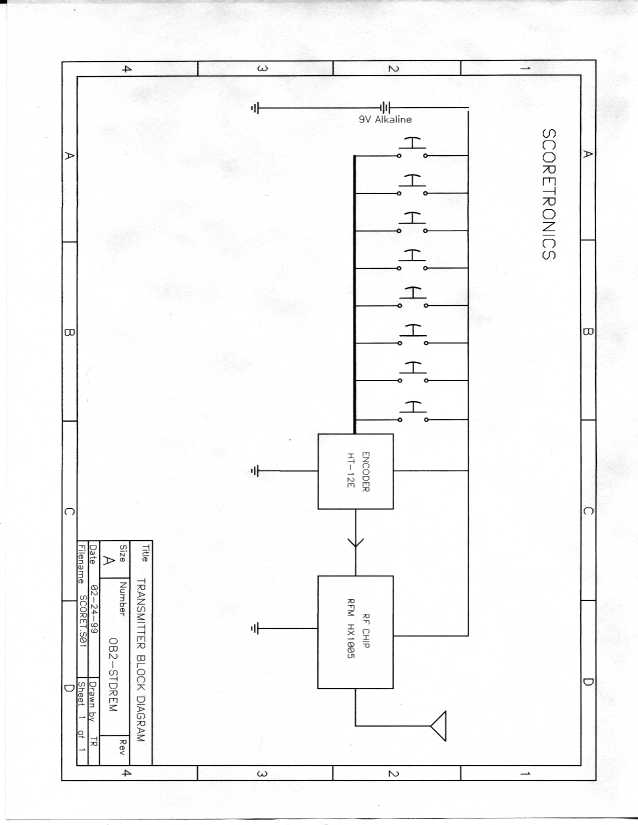
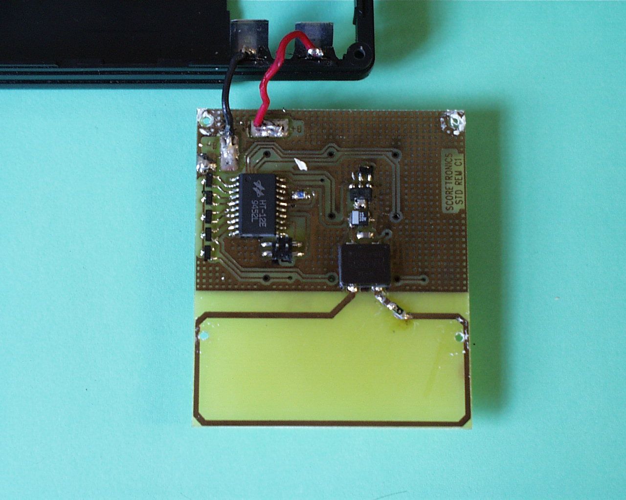
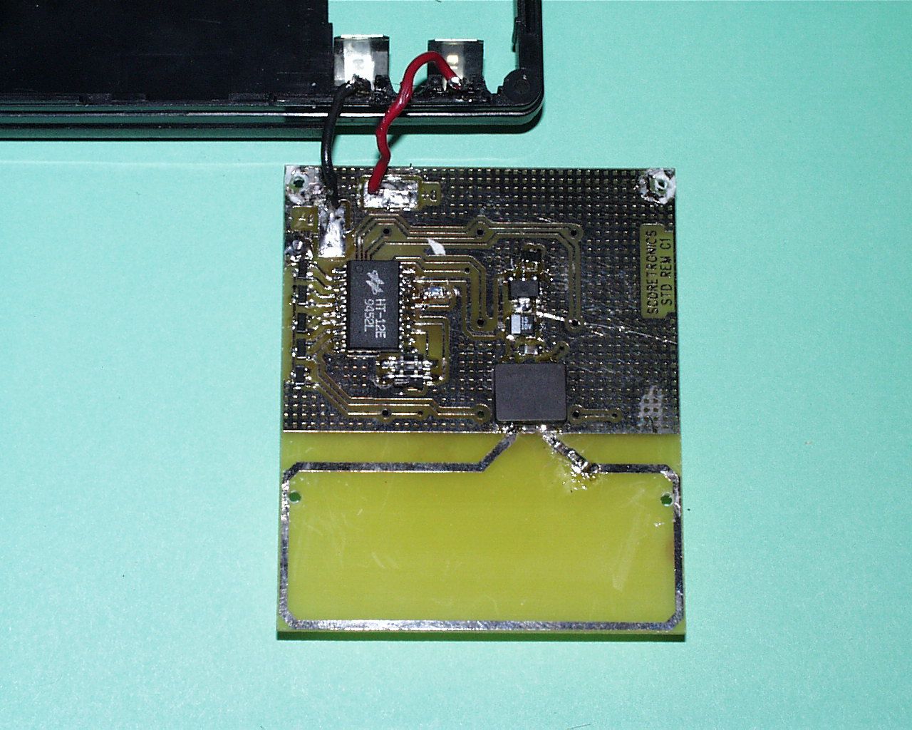
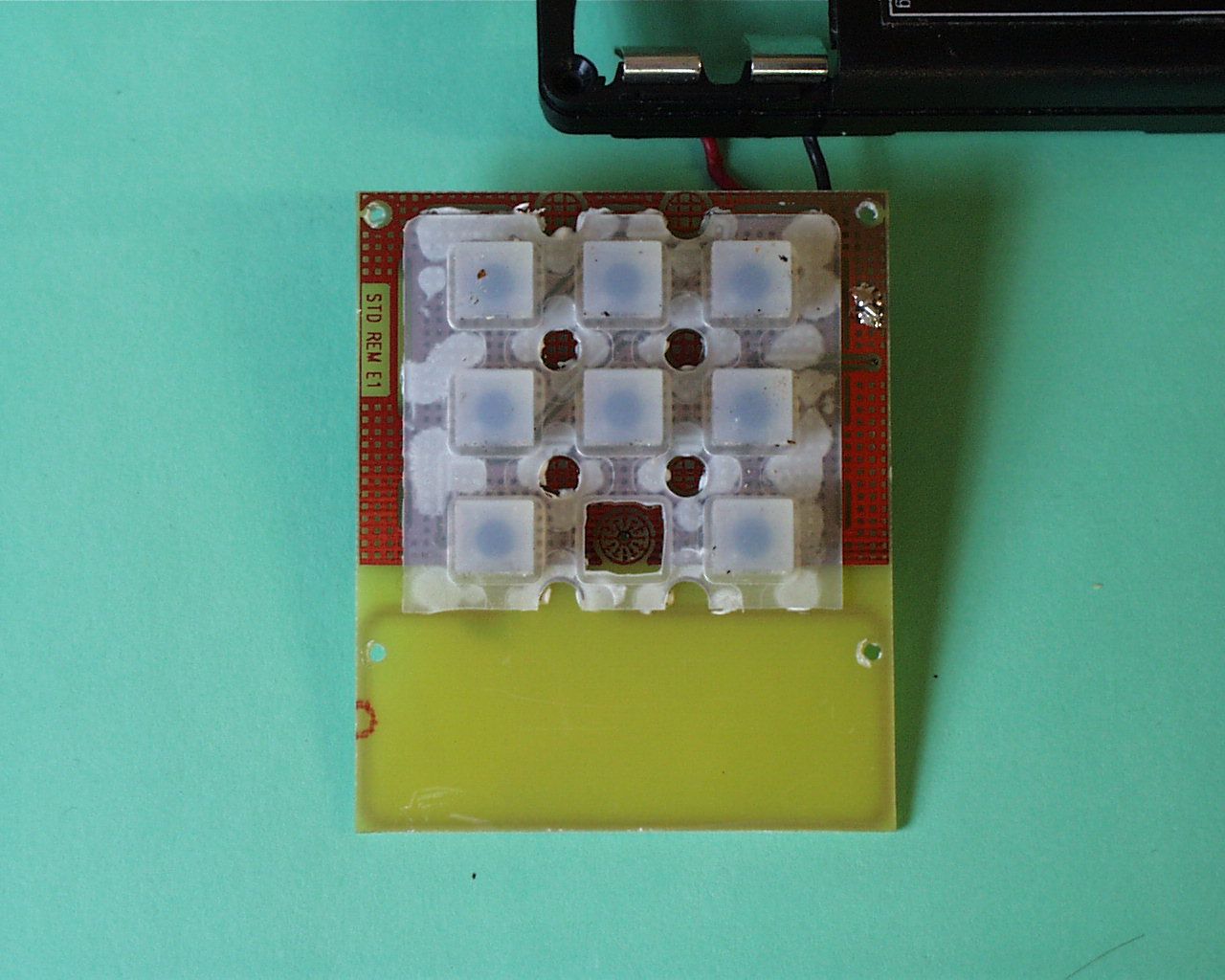
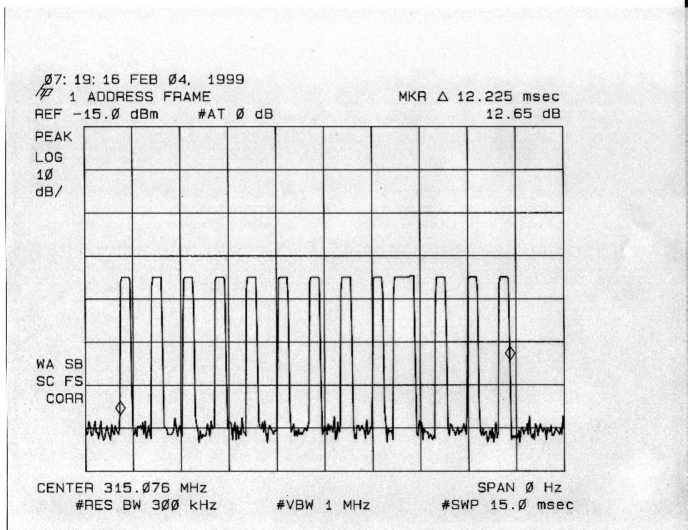
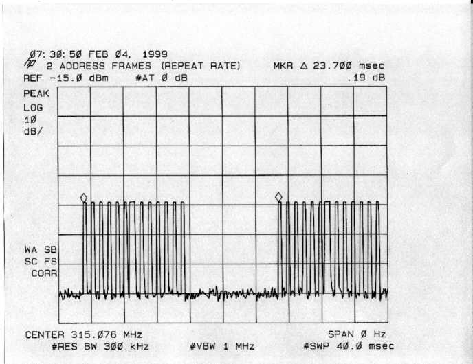
OB2-STD REMOTE Circuit Description & Schematic January 16, 1999 Power from a 9 volt battery enters the board and passes through a reverse battery protection diode D1, to the input of a low power three terminal voltage regulator IC1. IC1 regulates the output voltage down to 3.3 volts. C1 is used to stabilize the regulator output and improve the transient response of the regulator. IC2 is a keyboard scanner and encoder IC. R1 sets the frequency of the internal oscillator which determines the keyboard scanning rate and the timing of the output data stream. When a switch on the keyboard membrane is closed, the TE input of IC1 is pulled low through one of the isolation diodes (D2 - D6) and this brings IC1 out of sleep mode into active operation. IC1 scans the inputs AD11 to AD0 and creates a serial data stream out of pin 18 (DOUT). The output data from DOUT consists of pulses for each bit of 1/3 duty cycle for switches not closed and 2/3 duty cycle for switches that are closed, then the output goes idle (low) for 12 periods. In this application the duty cycle from the DOUT pin is approximately 17%. Signals from the DOUT pin of IC2 are fed to the data input of IC3. IC3 is an integrated On/Off keyed RF transmitter IC operating at 315 Mhz. Its RF frequency is internally controlled by its internal SAW oscillator, and output harmonics are controlled by its internal SAW output filter. The RF output of IC3 is fed through an antenna matching capacitor C3 and resistor R2 to a loop PCB trace antenna.
Test Report
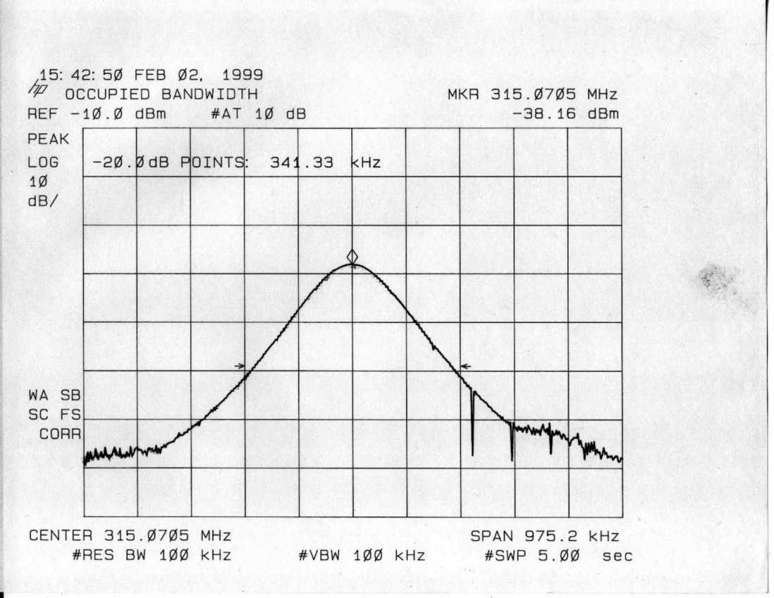
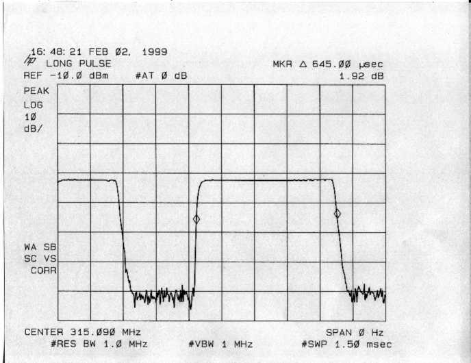
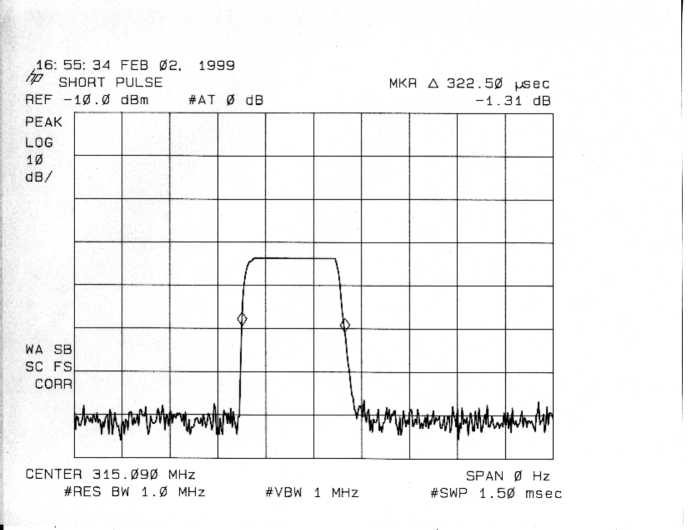
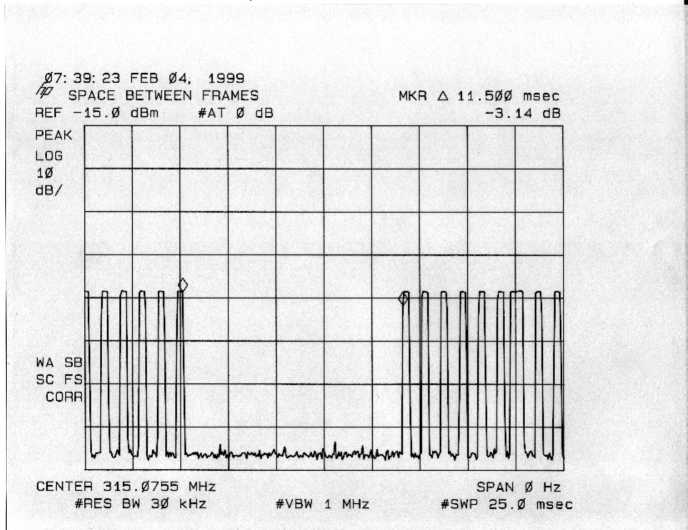
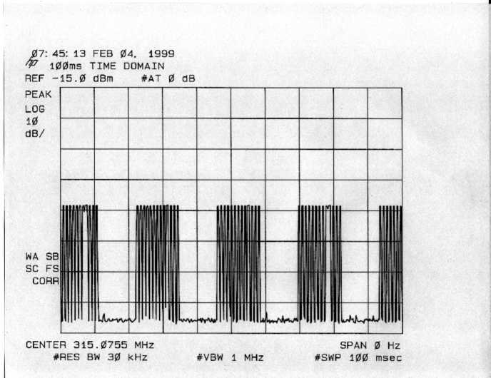
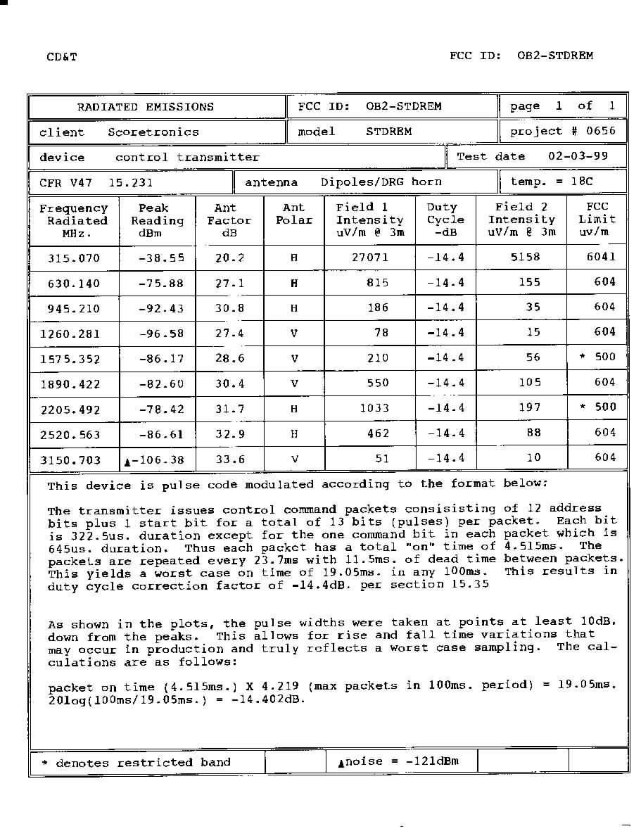
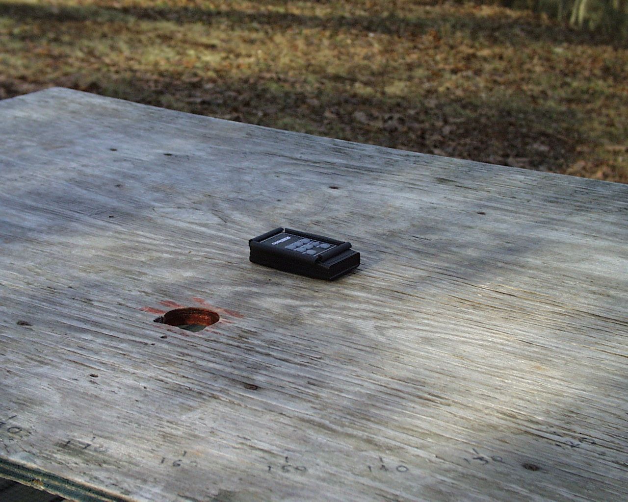
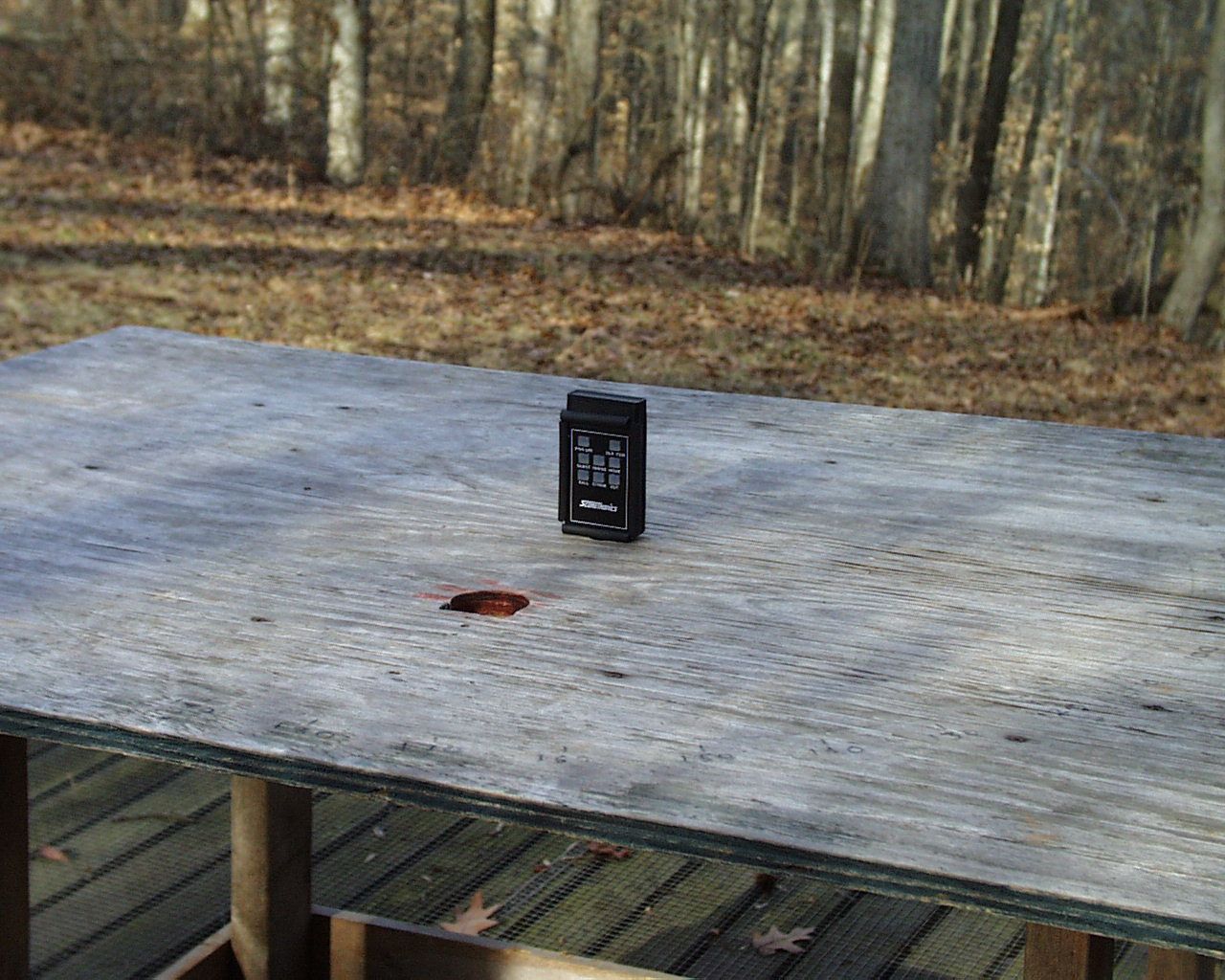
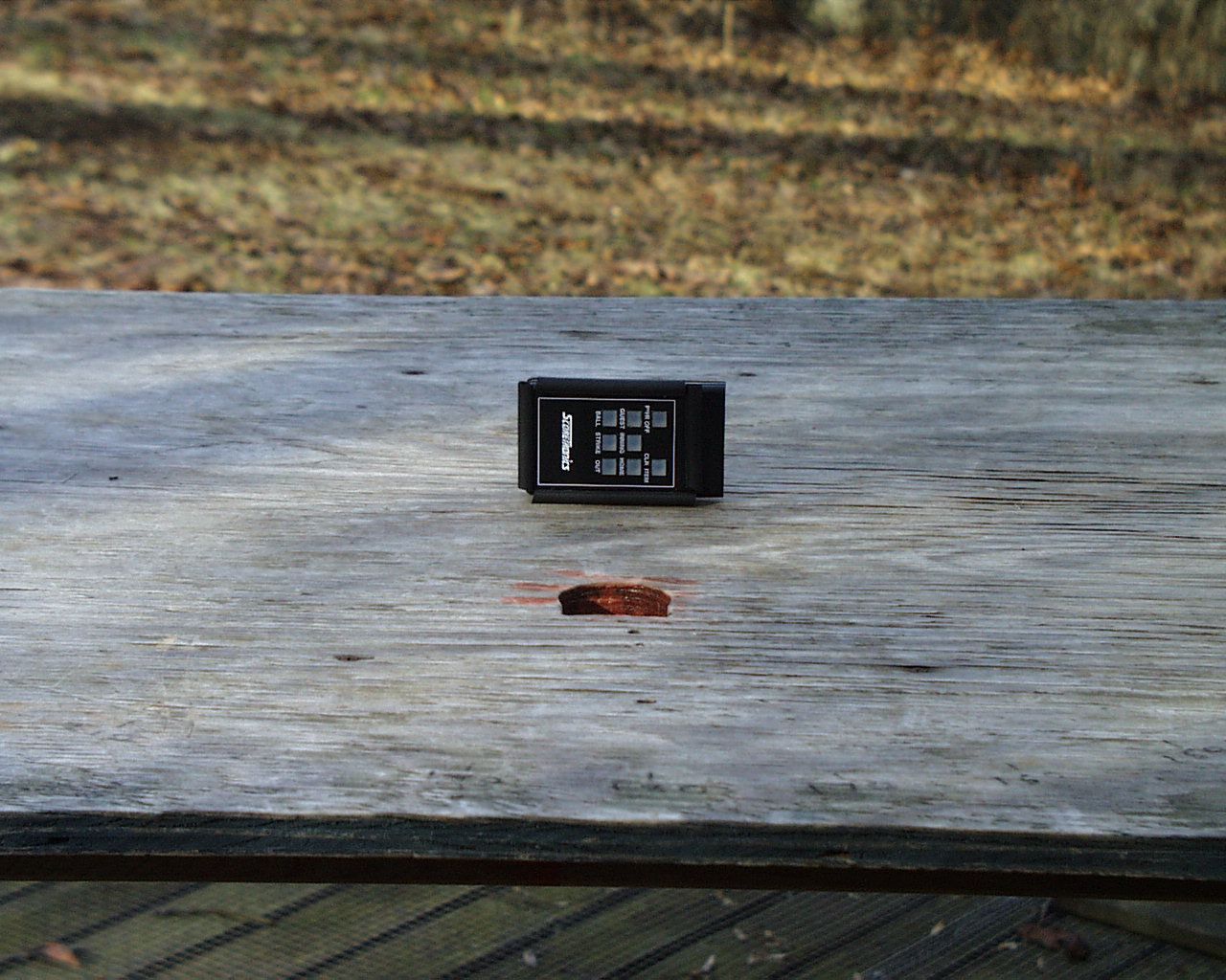
CD&T FCC ID: OB2-STDREM A. DEVICE UNDER TEST The device is a low power remote control transmitter operating under the provisions of Part 15.231 of the FCC rules. The transmit frequency is 315MHz.nominal. The modulation mode is on/off keying. B. MEASUREMENT PROCEDURE: RADIATED EMISSIONS Transmitter field strength measurements were conducted according to the procedures set forth in ANSI C63.4 (1992). The device under test was placed on a rotating turntable 0.8 meters high, centered at 3 meters distant from the measurement antenna. The device was placed in the center of the turntable and tested in three major planes as shown in the photographs The device is powered from an in internal 9V alkaline battery and is internally regulated at 3.3V. The test was conducted with a fresh battery. Several spare batteries were on hand for the test but the first battery was checked periodically and never dropped below 85% capacity. For the purposes of testing, the device was locked in a constant transmit mode by locking one of the pushbuttons in the on position. The field strength measurements were taken using an HP8596E spectrum analyzer, EMCO 3121C dipole set, an EMCO 3115 double ridge guide horn and an Avantek UJ210 preamp The device was scanned from 30MHz. to 4GHz. and all emissions were noted. In this case the only emissions detected were those harmonically related to the fundamental transmit frequency. At each detected frequency of emission, the device was measured by rotating the turntable and adjusting the antenna height over a range of 1 to 4 meters to obtain the maximum output level. This procedure was performed with both horizontal and vertical antenna polarizations with the device placed in the positions described above. The peak reading for each frequency was recorded in the second column on the data sheet. The readings for the ninth and tenth harmonics were obtained by reducing the distance from the measurement antenna to 1 meter and entering a -9.5dB distance correction factor into the final calculation for those measurements. The calculations for this device were adjusted by factoring in a duty cycle correction factor that was derived from an analysis of the time domain plots. This correction factor is given in the sixth column on the data sheet. The transmitted pulse durations were measured at points at least 6dB below peak to insure worst case averaging.
Contact Information
Applicant
Niel E Nielsen(President)
[email protected]630-571-1970
Technical Contact
Control Design and TestingTom W Roche
[email protected]540-582-2826
6010 Red Fox Drive · Spotsylvania, Virginia · United States
Non-Technical Contact
Control Design and TestingTom W Roche
[email protected]540-582-2826
Technical Specifications
| # | Rule Parts | Frequency Range | Power Output |
|---|---|---|---|
| 1 | 15C | 314.8 MHz - 315.2 MHz | - |
Other Applications from ScoreTronics, Inc.

OB2-PBA-4
May 05, 1999CYY - Communications Receiver used w/Pt 15 Transmitter
Equipment Class
CYY - Communications Receiver used w/Pt 15 Transmitter