OCP-PC0285
Industrial Service Technology
Click to zoom
Application Details
- Equipment Class
- DXX - Part 15 Low Power Communication Device Transmitter
- Date of Grant
- Mar 17, 1999
- Application Purpose
- Original Equipment
- Date of Application
- Jan 17, 1999
- Frequency Range
- 902.00000000 - 928.00000000
- Country
- United States
Documents & Files
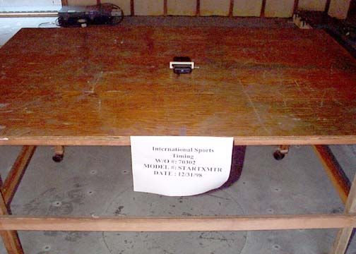
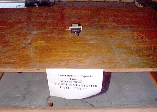
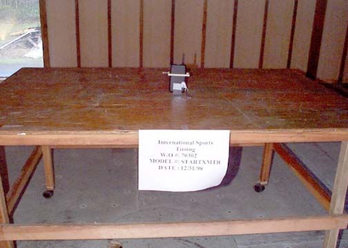
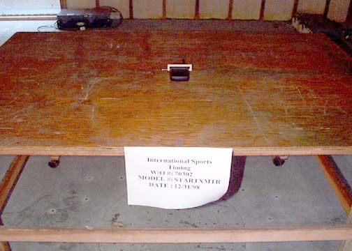
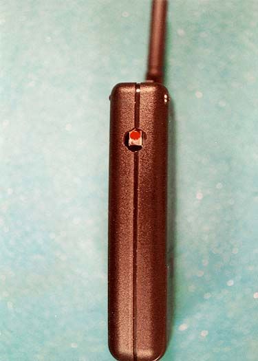
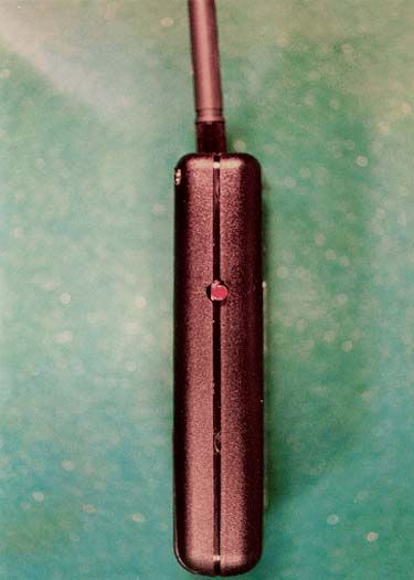
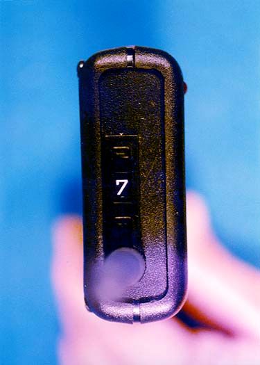
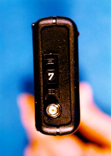
Document Text
Text extracted from the exhibit documents filed with the FCC. Open a document above to read the original.
Users Manual
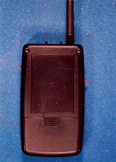
Congratulations on yourpurchase of the IST remote starting system. It wasdesigned for years oftrouble free use and ease ofoperation. Just hook up thereceiver to the microphonejack on your start and youare “wired” for sound!Please take a moment toread this owners manual tobecome familiar with thefeatures, operation andwarranty information.GENERAL The RF remote startingsystem consists of ahandheld transmitterpowered by a standard 9Vbattery and a receiver thatplugs directly in to yourexisting starting device.If you are using the IST SWIMSTART the power is supplied through theconnection to the receiver.If you are using another starting device a 9V batteryis also required for thereceiver. The receiverplugs into the microphonejack and mounts onto thestarting device using theVelcro strips supplied.The radio frequency link isin the 900 MHz frequencyrange and no license isrequired for operation.FCC NOTICE:This equipment has been tested andfound to comply with the limits for aClass B digital device, pursuant to part15 of the FCC Rules. These limits aredesigned to provide reasonableprotection against harmful interferencein a residential installation. Thisequipment generates, uses and canradiate radio frequency energy and, ifnot installed and used in accordancewith the instructions, may causeharmful interference to radiocommunications. However, there is noguarantee that interference will notoccur in a particular installation. Ifthis equipment does cause harmfulinterference to radio or televisionreception, which can be determined byturning the equipment off and on, theuser is encouraged to try to correct theinterference by one or more of thefollowing measures:• Reorient or relocate the receivingantenna. • Contact International SportsTiming for assistance. 800-835-2611. • MODIFICATIONS NOTEXPRESSELY APPROVED BYIST COULD VOID YOURAUTHORITY TO OPERATETHE EQUIPMENT. OPERATIONRECEIVER MOUNTINGFor best reception thereceiver should be mountedso that the antenna has asclear a view as possible ofthe site where the starterwill be standing. Anyplacewhere the antenna extendsabove the case will providea transmission range inexcess of 50 yards in mostapplications.Although it is not necessaryfor the operation of thedevice that the LED lightsare visible, they wereincorporated into the designto continually monitor foroutside interference, as well as inform the starter of therecall time period.They can also be used tohelp diagnose problems thatmay occur with the receiveror the start they areconnected to.INITIAL SET-UPOnce the receiver has beenconnected to the startdevice and the power hasbeen turned on, select anyof 8 channels (0-7) bydepressing either of thesmall buttons located on thechannel selector switch.Monitor the yellow“Carrier” LED to ensure itis NOT on at this time. If itis lit it indicates that thereis other activity on thischannel and anotherchannel should be selected.Next move the channelselect switch on thetransmitter to the same channel you chose for thereceiver.If the transmitter andreceiver channels are notthe same, the device willnot function.When the transmitters’push to talk button isdepressed the transmitter isturned on and an encodeddata signal is transmitted tothe receiver. When thereceiver detects the carriersignal coming from thetransmitter the yellow“Carrier” LED glows andthe green “Valid Receive”LED glows when theencoded signal issuccessfully decoded.This operation takes placein less than half a secondand was incorporated in thedesign to ensure that onlyour transmitter has thecorrect “key” to access thereceiver. This greatlyreduces the risk ofunwanted signal traffic breaking in unannouncedduring a meet.After this time, simply talkdirectly into themicrophone grate on thefront of the transmitter andadjust the volume controlon the starting device forthe proper audio level.STARTING A RACETo signal the start of anevent the start pushbutton isdepressed while the push totalk button is held down.Pushing the start buttonwhile the push to talkbutton is not depressed willnot initiate the start tone.This precaution wasimplemented to ensure thatthe tone is not accidentallystarted, and is in keepingwith the current wiredmicrophones. The tone will automaticallysound for about a quarter ofa second and stop.Immediately release thestart button once the tone isheard.Since the signal to start thetone is transmitted via radiolink instead of wire, itsounds for the same amountof time regardless of howlong the button isdepressed.The time the tone sounds isactually determined by thereceiver circuitry and thetransmitter start buttonneeds to be depressed foronly a fraction of a secondto produce the start tone.All of this is mentionedbecause if you have atendency to leave yourfinger on the start buttonand you are a little shakywhen you let off, it ispossible to retransmit thestart signal as you release the button. This couldinadvertently initiate therecall tone.While precautions havebeen taken to make thisevent highly unlikely, thebest way to prevent it is topress and release the startbutton quickly.RECALLING A RACEWhen a recall is warranted,simply use the transmitterin the same way you did tostart the race. After the startof a race there is a 10-second period where arecall tone will sound ifanother start signal isreceived.USING THE LED’sThe LED’s wereincorporated to give thestarter a sense of how theunit is functioning. Theyare used to identify outsideinterference, determine therecall time period, identify the current channel at aglance* and identify a lowbattery condition. **The yellow “Carrier” LEDwill light anytime there is aradio frequency signal onthe same channel as youhave selected. Besideslighting when the push totalk button is depressed, itwill light when othersources are present andcould interfere with theproper operation andrunning of the meet.It is advisable to monitorthe “Carrier” LED evenwhen you are not activelyusing the start device, as itwill alert you to possibleproblems due to outsideinterference.Th…
Text truncated - open the document above for the full version.
Attestation Statements
December 28, 1998 Federal Communications Commission 7435 Oakland Mills Road Columbia, MD 21046 Gentlemen: This letter is in reference to the equipment STARTXMTR, FCC ID: OCP-PC0285. This equipment has been tested in accordance with the requirements contained in the appropriate Commission regulations. To the best of my knowledge, these tests were performed using measurement procedures consistent with the Commissions standards and demonstrate that the equipment complies with the appropriate standards. Each unit manufactured, imported or marketed, as defined in the Commission’s regulations, will conform to the sample tested within the variations that can be expected due to quantity production and testing on a statistical basis. I further certify that the necessary measurements were made by: CKC Laboratories, Inc. 5473A Clouds Rest Mariposa, CA 95338 Attn: Tracy Swan Sincerely, Richard Farnsworth President/Owner
Cover Letter(s)
December 12, 1998 Federal Communications Commission 7435 Oakland Mills Road Columbia, MD 21046 Gentlemen: This is a letter of authorization to accept our appointment of CKC Laboratories, Inc. as Agent for Industrial Service Technology DBA International Sports Timing. We authorize CKC to sign applications before the Commission on our behalf, and to receive and exchange data between our company and the commission in connection with certification of the following International Sports Timing product: WIRELESS SWIMSTART Transmitter Model – STARTXMTR FCC ID: OCP-PC0285 We, the applicant certify that, in the case of individual applicant, he or she is not subject to a denial of federal benefits pursuant to section 5301 of the Anti-Drug Abuse Act of 1988, 21 USC 853a or in the case of non-individual applicant (e.g. corporation, partnership or other unincorporated association), no party to the applicant is subject to a denial of federal benefit pursuant to that action. This authorization will expire one year from the date of this letter. Sincerely, Richard Farnsworth President/Owner
Cover Letter(s)
December 28, 1998 Federal Communications Commission 7435 Oakland Mills Road Columbia, MD 21046 Gentlemen: This letter is to confirm that Industrial Service Technology DBA International Sports Timing would like the following documents regarding this submission for FCC ID: OCP-PC0285 to be kept confidential. • “xmtrschem.doc” This file contains block and schematic diagrams as well as circuit descriptions that we do not want to be accessible to the general public. Sincerely, Richard Farnsworth President/Owner
ID Label/Location Info
STARTRCVR MADE IN USA Tested to Comply With FCC Standards This device complies with part 15 of the FCC rules. Operation is subject to the following two conditions: (1) This device may not cause harmful interference, and (2) this device must accept any interference received, including interference that may cause undesired operation. FCC ID: OCP-PC0285 STARTXMTR This device complies with part 15 of the FCC rules. Operation is subject to the following two conditions: (1) This device may not cause harmful interference, and (2) this device must accept any interference received, including interference that may cause undesired operation. MADE IN USA
ID Label/Location Info
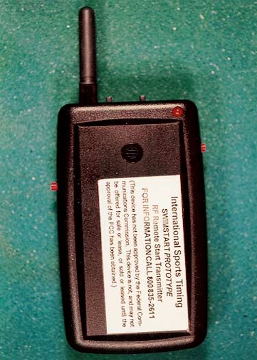
The FCC ID is affixed to the rear of the transmitter with BRADY XB-423 thermal transfer printable glossy white polyester label stock. The specifications of the label material follow.
Test Report
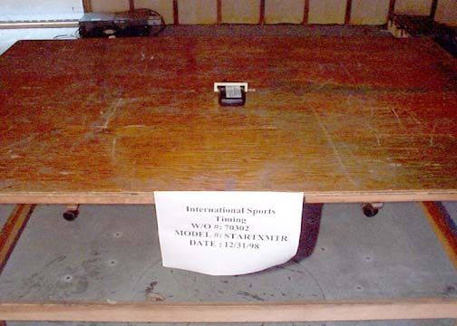
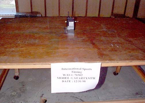
Page 1 of 27 Report No: FC99-001 CERTIFICATION TEST REPORT FOR THE TRANSMITTER, STARTXMTR FCC PART 15 SUBPART C COMPLIANCE DATE OF ISSUE: JANUARY 6, 1999 PREPARED FOR: Industrial Service Technology DBA International Sports Timing 3286 Kentland Court, S.E. Grand Rapids, MI 49548 P.O. No: 9181 W.O. No: 70302 PREPARED BY: Joyce Walker CKC Laboratories, Inc. 5473A Clouds Rest Mariposa, CA 95338 Dates of test: December 31, 1998 & January 4, 1999 Report No: FC99-001 DOCUMENTATION CONTROL: _____________________________ Tracy Phillips Documentation Control Supervisor CKC Laboratories, Inc. APPROVED BY: _____________________________ Dennis Ward Director of Laboratories CKC Laboratories, Inc. This report contains a total of 27 pages and may be reproduced in full only. Partial reproduction may only be done with the written consent of CKC Laboratories, Inc. Page 2 of 27 Report No: FC99-001 TABLE OF CONTENTS Administrative Information..........................................................................................3 Summary Of Results....................................................................................................4 Equipment Under Test (EUT) Description...................................................................4 Measurement Uncertainty............................................................................................4 EUT Operating Frequency...........................................................................................4 Peripheral Devices.......................................................................................................4 Report Of Measurements.............................................................................................5 Table 1: Six Highest Radiated Emission Levels................................................5 Table A: List Of Test Equipment................................................................................6 EUT Setup...................................................................................................................7 Test Instrumentation And Analyzer Settings................................................................7 Table B : Analyzer Bandwidth Settings Per Frequency Range..........................7 Spectrum Analyzer Detector Functions.............................................................8 Peak......................................................................................................8 Quasi-Peak............................................................................................8 Average................................................................................................8 Test Methods...............................................................................................................9 Radiated Emissions Testing..............................................................................9 Occupied Bandwidth........................................................................................9 Sample Calculations.....................................................................................................10 Appendix A : Information About The Equipment Under Test......................................11 I/O Ports...........................................................................................................12 Crystal Oscillators............................................................................................12 Printed Circuit Boards......................................................................................12 Required EUT Changes To Comply..................................................................12 Photograph Showing Radiated Emissions.........................................................13 Photograph Showing Radiated Emissions.........................................................14 Photograph Showing Radiated Emissions.........................................................15 Photograph Showing Radiated Emissions.........................................................16 Photograph Showing Radiated Emissions.........................................................17 Photograph Showing Radiated Emissions.........................................................18 Appendix B : Measurement Data Sheets......................................................................19 Occupied Bandwidth Plot.................................................................................20 Occupied Bandwidth Plot.................................................................................21 Page 3 of 27 Report No: FC99-001 CKC Laboratories, Inc. has Certificates of Accreditation from the following agencies: DATech (Germany); A2LA (USA); FCC (USA); VCCI (Japan); BCIQ (Taiwan); HOKLAS (Hong Kong). CKC Laboratories, Inc. has Letters of Acceptance through an MRA for the following agencies: ACA/NATA (Australia); SABS (South Africa); SWEDAC (Sweden); TUV Rheinland-Germany; TUV Rheinland- Korea; TUV Rheinland-Russia; Radio Communication Agency (RA); NEMKO (Norway). ADMINISTRATIVE INFORMATION DATE OF TEST: December 31, 1998 & January 4, 1999 PURPOSE OF TEST: To demonstrate the compliance of the Transmitter, STARTXMTR, with the requirements for FCC Part 15, Subpart C devices. MANUFACTURER: Industrial Service Technology DBA International Sports Timing 3286 Kentland Court, S.E. Grand Rapids, MI 49548 REPRESENTATIVE: Richard Farnsworth TEST LOCATION: CKC Laboratories, Inc. 22105 Wilson River Hwy Tillamook, OR 97141 TEST PERSONNEL: Adam Ross TEST METHOD: ANSI C63.4 1992 FREQUENCY RANGE TESTED: 30 MHz - 10GHz EQUIPMENT UNDER TEST:Transmitter Manuf: LINX Model: STARTXMTR Serial: Prototype FCC ID: OCP-PC0285 (pending) Page 4 of 27 Report No: FC99-001 SUMMARY OF RESULTS The Industrial Service Technology DBA International Sports Timing Transmitter, STARTXMTR, was tested in accordance with ANSI C63.4 1992 for compliance with FCC Part 15, Subpart C. As received, the above equipment was found to be fully com…
Text truncated - open the document above for the full version.
Contact Information
Applicant
Richard Farnsworth(President/Owner)
800-835-2611Fax: 616-247-0086
Technical Contact
CKC Laboratories, Inc.Tracy Phillips
[email protected]1-800-500-4362
5473A Clouds Rest · Mariposa, California · United States
Non-Technical Contact
CKC Laboratories, Inc.Joyce Walker
[email protected]1-800-500-4362
Test Firm
CKC Laboratories, Inc.Steve Behm
Technical Specifications
| # | Rule Parts | Frequency Range | Power Output |
|---|---|---|---|
| 1 | 15C | 902 MHz - 928 MHz | - |