OCQLA-WIWPROXKEYMSecurity Badge Reader
Iolan Systems Inc.
Click to zoom
Application Details
- Equipment Class
- DXX - Part 15 Low Power Communication Device Transmitter
- Date of Grant
- Jul 14, 1999
- Application Purpose
- Original Equipment
- Date of Application
- Apr 11, 1999
- Equipment Note
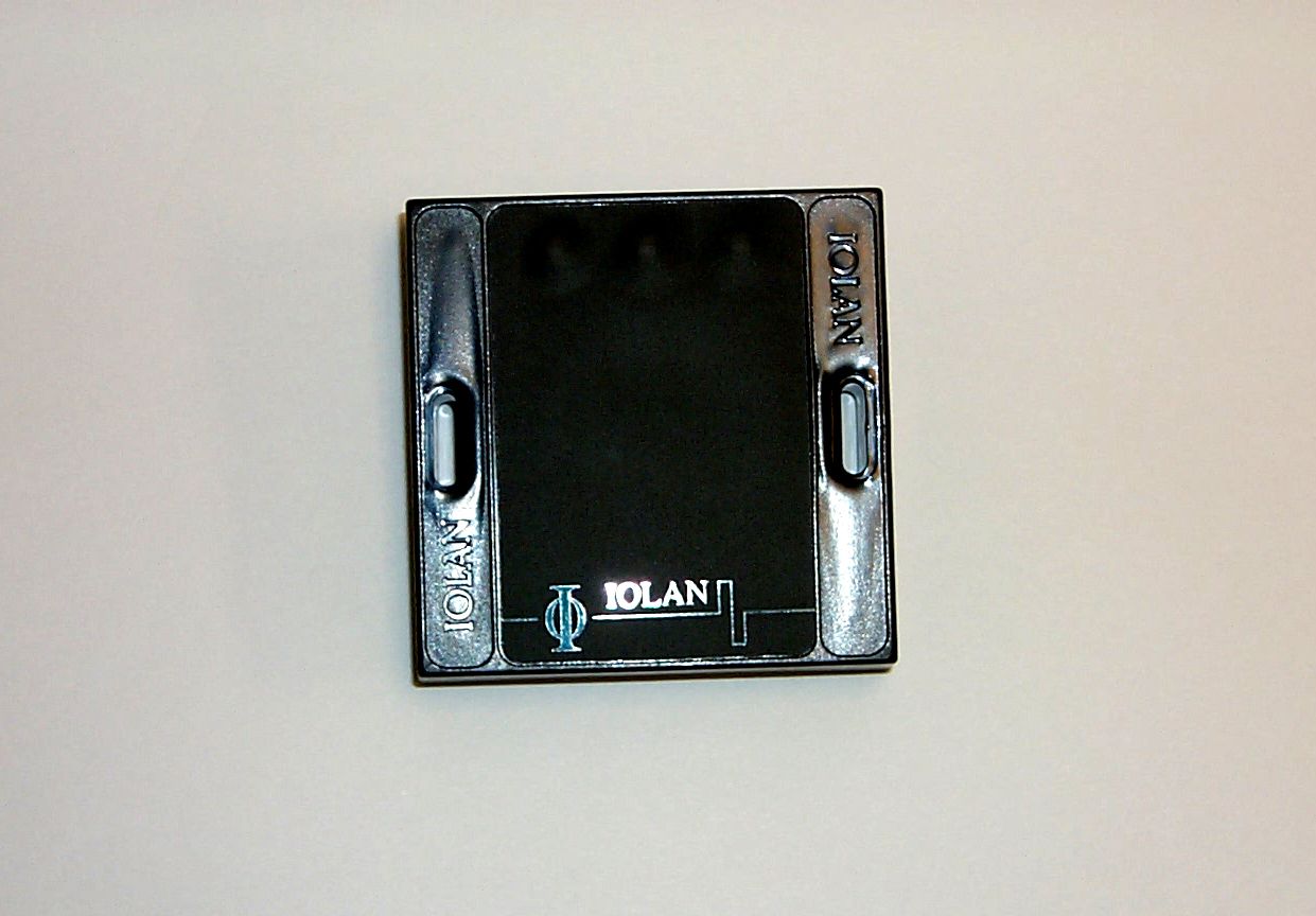
- Security Badge Reader
- Frequency Range
- 13.56000000 - 13.56000000
- Company
- Iolan Systems Inc.
- Country
- United States
Documents & Files
Document Text
Text extracted from the exhibit documents filed with the FCC. Open a document above to read the original.
Users Manual
September 21, 1998www.iolan.comPage: 1 Iolan Systems, Inc. 1200 Barton Hills Dr. Suite 233 Austin, Texas 78704 Tel: (512) 443-4369 Fax: (512) 443-3615 SALES SPECIFICATIONS LA-WIW-PROXKEY-M Gerard Verkaart President Email: [email protected] LA WIW Proxkey M ISIBR.docwww.iolan.comPage: 2 1.Contents 1.CONTENTS..........................................................................................................................................................2 2.PURPOSE OF THIS DOCUMENT....................................................................................................................3 3.DESCRIPTION OF THE READER...................................................................................................................3 4.DATA AND RELATION WITH TC NETWORK............................................................................................3 5.TECHNICAL DATA............................................................................................................................................4 6.PARAMETERS OF THE MODULE.................................................................................................................5 7.DIMENSIONS OF THE MODULE:..................................................................................................................5 8.CONNECTING.....................................................................................................................................................6 9.THE WIEGAND INTERFACE..........................................................................................................................7 10.THE LED INTERFACE..................................................................................................................................7 11.WIEGAND PROTOCOL................................................................................................................................8 12.CHARACTER COMPOSITION....................................................................................................................8 13.METHOD OF SENDING AND TIMING......................................................................................................9 LA WIW Proxkey M ISIBR.docwww.iolan.comPage: 3 2.Purpose of this document This document gives a full explanation of the possibilities of the LA-WIW-PROXKEY-M. This information can be used, for example, in sales documentation. 3.Description of the reader The LA-WIW-PROXKEY-M is a ‘wallmount-module,’ a reader for MIFARE® tags. The module is designed for identification purposes. It uses a Wiegand data-interface to read a card number, or any other kind of data, and to send it to the connecting unit. There are three indicators: red, green and yellow. The yellow lamp blinks when the card is successfully read. A buzzer is available to give signals as programmed 4.Data and Relation with TC Network The reader can be connected to a network as shown in this scheme: PC MET IOLAN_TC BEHEER NETWORKITEM : LA-WIW-PROXKEY-B SERVER NETWERK MET DATABASEPC MET IOLAN_TC PC-LAN SPANT 3 SPANT 4 LA-TCR-RSOMZ-B SYSTEEM MET MEERDERE MODULEN KANAALNUMMERS DIENEN ALS VOORBEELD EENVOUDIGSTE OPSTELLING RS232-KABEL PC MET IOLAN_TC LA-TCB-2WI-2I-2R K8 LA-TCK-2WI-4I-2Y K9220Vac LA-TCB-PANEL K10 LA-TCX-DISPLAY K11 LA-TCR-RSOMZ-B LA-TCB-8AN SPANT 1 SPANT 2 K12 ANALOGE INPUTSDISPLAY MODULE LA-CHP-8A-8S-H LA-CHP-8A-8S-V LA-CHP-8A-8S-R2X LA-WIW-PROXKEY-B LA-WIW-PROXKEY-B LA-TCK-2WI-4I-2Y & LA-TCI-RSOMZ-A 220Vac LA-WIW-PROXKEY-B LA-WIX-PROXKEY-M LA-CHR-8I-8Y LA-CHR-16I-16Q LA-CHP-8A-8S-G DIGITALE INPUT EN OUTPUT IOLAN GEBOUWAUTOMATISERING PROJECTNAAM ONDERWERP : : STANDAARDISERING IOLAN NETWERK LA-WIW-PROXKEY-BDEEL :NETWERKSYMBOLIEK GET. GEW. GEW. GEW. E.LEMMPROJECTNR. TEKENING NR. 13-10-1997 R086 E003 LA WIW Proxkey M ISIBR.docwww.iolan.comPage: 4 5.Technical data Input Input • 5..0 Volt. The power input is included in the 6 pins connector. In cooperation with IOLAN-modules the power is supplied. • 50..80mA. Technical data WI interface • 6 pins connector with: • 2x power supply • 2x lamp switcher • 2x data. Wiegand ‘clock-data’ • Data structure according to ISO 7811/2-1986 TRACK 2 Reading distance • 20mm typical, min 10mm max 30mm met transponder types : MF1- S50, MF1-P60 en MF1-L10 Operating frequency • 13,56mhz. Data-transport transmitting speed • 106kBd Security • Data encrypted, protected against recording and ‘replay-attack’. Possibilities Transponders • Can read from MIFARE® card types 1, 2, and 3. • Reader can hold one key (A or B) and one read location for transponder-identification. • Flexible transponder-code length. Indicators • Yellow LED-lamp and buzzer for successful reading action • Red LED-lamp and green LED-lamp for logistic matters. E.g.: red: no access; green: access allowed. Mechanical aspects Material housing • Typical W-housing • Black plastic housing, ABS plastic house. • Dimensions (without connectors; HxBxL mm ) 21x71x71mm. See drawing R086EF02. Connection to wall • 2x 3mm opening on 60mm distance. See drawing R086EF02. Cable connectors • Max. diameter 1.5 mm 2 • Connectors 1x6 pins Protection • When connector-protected IP66. Temperature • Stock -10..70 o Celsius • Operating temp 0..50 o Celsius Installation Connectors • 6 pins. Thus maximum of 6 connecting wires Mounting place • When mounting, outside connector must be protected with lacquer, or the edges must be made watertight. Ordering information TypeLA WIW Proxkey M Order numberLA 0110 01 LA WIW Proxkey M ISIBR.docwww.iolan.comPage: 5 6.Parameters of the module There are no switches on the module; however, according to the MIFARE protocol the readers must be personalized. There is a procedure available which accomplishes this. During this personalization-procedure, the key and pointers are downloaded. The key is necessary to gain access to an application on the transponder. The pointers determine where the information is located. The reader is constructed in such a way t…
Text truncated - open the document above for the full version.
Users Manual
September 21, 1998www.iolan.comPage: 1 Iolan Systems, Inc. 1200 Barton Hills Dr. Suite 233 Austin, Texas 78704 Tel: (512) 443-4369 Fax: (512) 443-3615 SALES SPECIFICATIONS LA-WIW-PROXKEY-M Gerard Verkaart President Email: [email protected] LA WIW Proxkey M ISIBR.docwww.iolan.comPage: 2 1.Contents 1.CONTENTS..........................................................................................................................................................2 2.PURPOSE OF THIS DOCUMENT....................................................................................................................3 3.DESCRIPTION OF THE READER...................................................................................................................3 4.DATA AND RELATION WITH TC NETWORK............................................................................................3 5.TECHNICAL DATA............................................................................................................................................4 6.PARAMETERS OF THE MODULE.................................................................................................................5 7.DIMENSIONS OF THE MODULE:..................................................................................................................5 8.CONNECTING.....................................................................................................................................................6 9.THE WIEGAND INTERFACE..........................................................................................................................7 10.THE LED INTERFACE..................................................................................................................................7 11.WIEGAND PROTOCOL................................................................................................................................8 12.CHARACTER COMPOSITION....................................................................................................................8 13.METHOD OF SENDING AND TIMING......................................................................................................9 LA WIW Proxkey M ISIBR.docwww.iolan.comPage: 3 2.Purpose of this document This document gives a full explanation of the possibilities of the LA-WIW-PROXKEY-M. This information can be used, for example, in sales documentation. 3.Description of the reader The LA-WIW-PROXKEY-M is a ‘wallmount-module,’ a reader for MIFARE® tags. The module is designed for identification purposes. It uses a Wiegand data-interface to read a card number, or any other kind of data, and to send it to the connecting unit. There are three indicators: red, green and yellow. The yellow lamp blinks when the card is successfully read. A buzzer is available to give signals as programmed 4.Data and Relation with TC Network The reader can be connected to a network as shown in this scheme: PC MET IOLAN_TC BEHEER NETWORKITEM : LA-WIW-PROXKEY-B SERVER NETWERK MET DATABASEPC MET IOLAN_TC PC-LAN SPANT 3 SPANT 4 LA-TCR-RSOMZ-B SYSTEEM MET MEERDERE MODULEN KANAALNUMMERS DIENEN ALS VOORBEELD EENVOUDIGSTE OPSTELLING RS232-KABEL PC MET IOLAN_TC LA-TCB-2WI-2I-2R K8 LA-TCK-2WI-4I-2Y K9220Vac LA-TCB-PANEL K10 LA-TCX-DISPLAY K11 LA-TCR-RSOMZ-B LA-TCB-8AN SPANT 1 SPANT 2 K12 ANALOGE INPUTSDISPLAY MODULE LA-CHP-8A-8S-H LA-CHP-8A-8S-V LA-CHP-8A-8S-R2X LA-WIW-PROXKEY-B LA-WIW-PROXKEY-B LA-TCK-2WI-4I-2Y & LA-TCI-RSOMZ-A 220Vac LA-WIW-PROXKEY-B LA-WIX-PROXKEY-M LA-CHR-8I-8Y LA-CHR-16I-16Q LA-CHP-8A-8S-G DIGITALE INPUT EN OUTPUT IOLAN GEBOUWAUTOMATISERING PROJECTNAAM ONDERWERP : : STANDAARDISERING IOLAN NETWERK LA-WIW-PROXKEY-BDEEL :NETWERKSYMBOLIEK GET. GEW. GEW. GEW. E.LEMMPROJECTNR. TEKENING NR. 13-10-1997 R086 E003 LA WIW Proxkey M ISIBR.docwww.iolan.comPage: 4 5.Technical data Input Input • 5..0 Volt. The power input is included in the 6 pins connector. In cooperation with IOLAN-modules the power is supplied. • 50..80mA. Technical data WI interface • 6 pins connector with: • 2x power supply • 2x lamp switcher • 2x data. Wiegand ‘clock-data’ • Data structure according to ISO 7811/2-1986 TRACK 2 Reading distance • 20mm typical, min 10mm max 30mm met transponder types : MF1- S50, MF1-P60 en MF1-L10 Operating frequency • 13,56mhz. Data-transport transmitting speed • 106kBd Security • Data encrypted, protected against recording and ‘replay-attack’. Possibilities Transponders • Can read from MIFARE® card types 1, 2, and 3. • Reader can hold one key (A or B) and one read location for transponder-identification. • Flexible transponder-code length. Indicators • Yellow LED-lamp and buzzer for successful reading action • Red LED-lamp and green LED-lamp for logistic matters. E.g.: red: no access; green: access allowed. Mechanical aspects Material housing • Typical W-housing • Black plastic housing, ABS plastic house. • Dimensions (without connectors; HxBxL mm ) 21x71x71mm. See drawing R086EF02. Connection to wall • 2x 3mm opening on 60mm distance. See drawing R086EF02. Cable connectors • Max. diameter 1.5 mm 2 • Connectors 1x6 pins Protection • When connector-protected IP66. Temperature • Stock -10..70 o Celsius • Operating temp 0..50 o Celsius Installation Connectors • 6 pins. Thus maximum of 6 connecting wires Mounting place • When mounting, outside connector must be protected with lacquer, or the edges must be made watertight. Ordering information TypeLA WIW Proxkey M Order numberLA 0110 01 LA WIW Proxkey M ISIBR.docwww.iolan.comPage: 5 6.Parameters of the module There are no switches on the module; however, according to the MIFARE protocol the readers must be personalized. There is a procedure available which accomplishes this. During this personalization-procedure, the key and pointers are downloaded. The key is necessary to gain access to an application on the transponder. The pointers determine where the information is located. The reader is constructed in such a way t…
Text truncated - open the document above for the full version.
Attestation Statements
EMC Automation 1101 CYPRESS CREEK RD • CEDAR PARK TX 78613 • USA PHONE: (+1) 512-258-9478 • FAX: (+1) 512-258-0740 WWW.EMC-AUTOMATION.COM A TDK Group Company FORM 731 ATTACHMENT RF Exposure Confirmation Number: EA93833 FCC ID: OCQLA-WIWPROXKEYM The device referenced above is an extremely weak, fixed location, 13.56MHz transmitter. The maximum power output is 0.4W. (See manufacture’s information.) Based on this information and the criterion set by the FCC, no specific absorption rate (SAR) exposure limits are exceeded.
Block Diagram
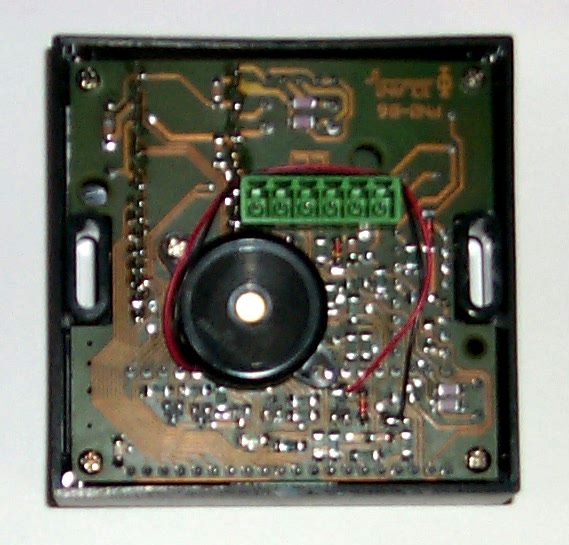
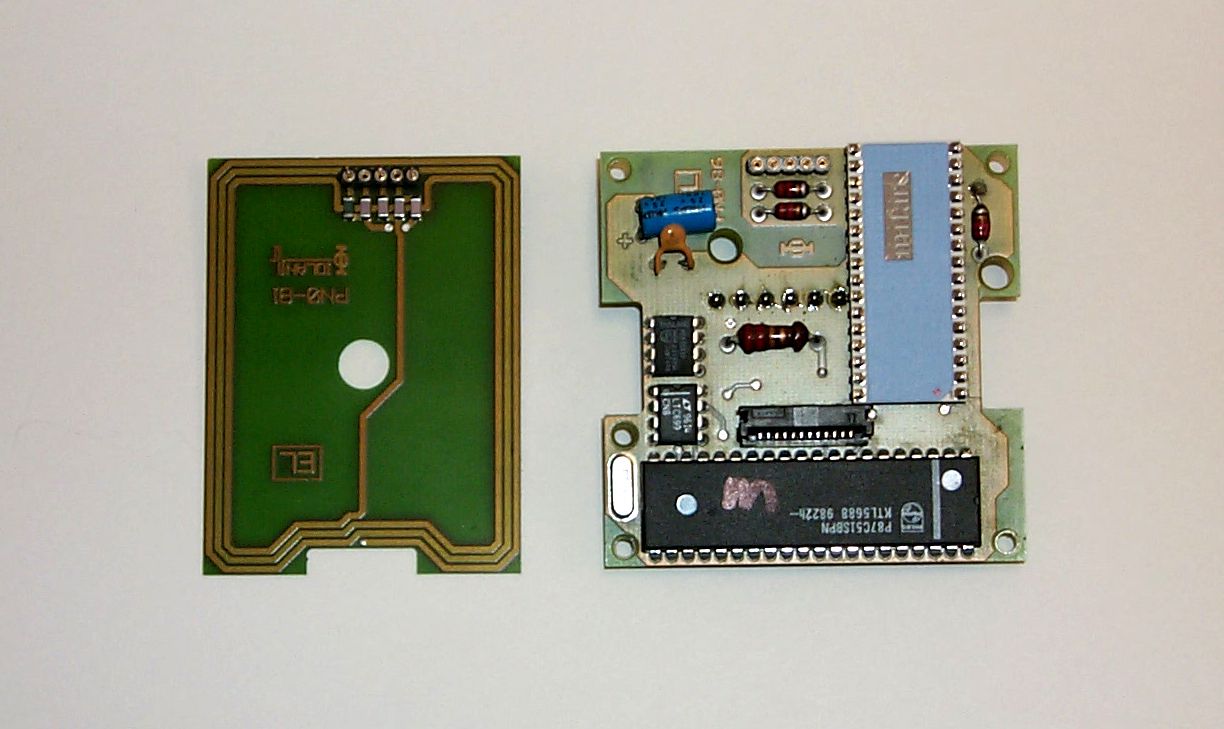
EMC Automation 1101 CYPRESS CREEK RD • CEDAR PARK TX 78613 • USA PHONE: (+1) 512-258-9478 • FAX: (+1) 512-258-0740 WWW.EMC-AUTOMATION.COM A TDK Group Company FORM 731 ATTACHMENT Block Diagram Confirmation Number: EA93833 FCC ID: OCQLA-WIWPROXKEYM This product is described by a simple diagram. (See the schematic diagram circuit.) The only clock frequency supplied is generated by crystal, X1. The frequency is 11.059MHz. The device radiates at a frequency of 13.56MHz.
Cover Letter(s)
EMC Automation 1101 CYPRESS CREEK RD • CEDAR PARK TX 78613 • USA PHONE: (+1) 512-258-9478 • FAX: (+1) 512-258-0740 WWW.EMC-AUTOMATION.COM A TDK Group Company Federal Communications CommissionApril 12, 1999 Office of Engineering and Technology Equipment Authorization Division, Customer Service Branch 7435 Oakland Mills RD Columbia, MD 21046 Confirmation Number: EA93833 FCC ID: OCQLA-WIWPROXKEYM To Whom It May Concern: My name is Michael E. Hill. I am the Manager-Test Facility for EMC Automation. We recently tested the Iolan Systems Inc. (ISI) LA-WIW-Proxkey-M badge reader to CFR47 Part 15. The device is an intentional radiator (13.56MHz), digital device (11MHz). As such, it requires certification with the FCC. It is our opinion this device conforms to the requirements of Part 15. The sample tested met these standards without modification. On behalf of ISI and their representative Gerard Verkaart, EMCA is handling the Form 731 filing for this product. This will be an electronic submittal. Form 731 has been filed electronically and Form 159 and the necessary payment have been mailed to the FCC. ISI requests that the schematic diagram of the device be kept confidential. Any questions regarding this submittal (i.e. missing information), should be forwarded to me. Please feel free to use my email address: [email protected]. As this is our first electronic filing, EMCA would appreciate any comments you may have that will expedite this process in the future. Sincerely, Manager Test Facility Cc: Gerard Verkaart ISI
ID Label/Location Info
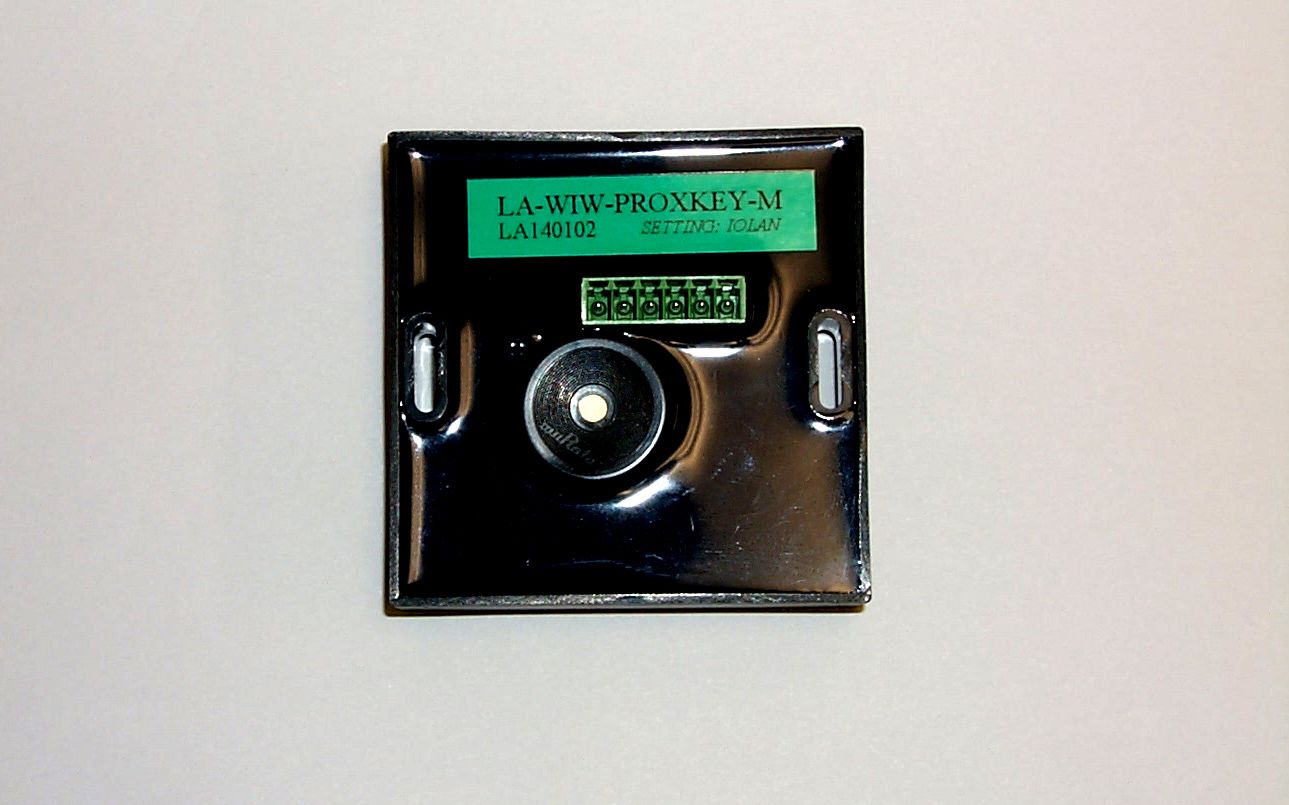
EMC Automation 1101 CYPRESS CREEK RD • CEDAR PARK TX 78613 • USA PHONE: (+1) 512-258-9478 • FAX: (+1) 512-258-0740 WWW.EMC-AUTOMATION.COM A TDK Group Company FORM 731 ATTACHMENT Label Confirmation Number: EA93833 FCC ID: OCQLA-WIWPROXKEYM A label will be permanently attached to the product on the top edge. The label will state: FCC ID: OCQLA-WIWPROXKEYM Model No.: LA-WIW-PROXKEY-M Serial Number: <########> In addition, product literature will also state: This device complies with part 15 of the FCC Rules. Operation is subject to the fol- lowing two conditions: (1) This device may not cause harmful interference, and (2) this device must accept any interference re- ceived, including interference that may cause undesired operation .
Parts List/Tune Up Info
EMC Automation 1101 CYPRESS CREEK RD • CEDAR PARK TX 78613 • USA PHONE: (+1) 512-258-9478 • FAX: (+1) 512-258-0740 WWW.EMC-AUTOMATION.COM A TDK Group Company FORM 731 ATTACHMENT Parts List/Tune Up Info Confirmation Number: EA93833 FCC ID: OCQLA-WIWPROXKEYM The FCC document INSTRUCTIONS FOR SUBMITTING FCC FORM 731 ATTACHMENTS sites 2.983 of CFR47 as the reference for this document. However, I am unable to find the reference in the latest version in the CFR. The section numbering goes 2.956 then skips to 2.1031. Nonetheless the parts list info has been requested from the manufacturer and will be forwarded upon receipt. The device does not require a tune up . It immediately begins radiating at 13.56MHz upon application of +5V.
Test Report
EMCA Test Report: ISI0001-99, Rev. A 1.0 PURPOSE This test report applies to the Iolan Systems, Inc. (ISI) LA-WIW-PROXKEY-M badge reader(see Fig. 1). This wall-mount module is designed for identification purposes. Access to a facility or identity established when a badge is held close to the reader. Figure 1 The purpose of this electromagnetic compatibility (EMC) Test Report is to give the FCC information on the radiated emission profile of the badge reader as required for 47 CFR Ch. I (10- 1-97 Edition) Part 15-Radio Frequency Devices, Subpart C-Intentional Radiators and Subpart B- Unintentional Radiators. For sake of brevity, this standard will be referred to as FCC Part 15. The badge reader emits a weak RF field to activate the badge. Obviously, it is a Subpart C device. Since the badge reader contains a microcontroller and is part of a distributed network, it is a computer peripheral and is subject to Subpart B levels also. FCC Part 15 testing is performed using the techniques and practices described in the “American National Standard for Methods of Measurement of Radio Noise Emission from Low-Voltage Electrical and Electronic Equipment in the Range of 9KHz to 40GHZ”, ANSIC63.4-1992. The target emissions levels are set using criterion set in FCC Part 15. The badge reader is powered by a DC voltage via it’s controller, no conducted emissions testing was necessary. The heart of the device is a MIFARE Micro Module MF CM200 hybrid. Manufacturer’s data sheet is available at: http://www-us.semiconductors.com/identification/mfcm200.stm.html EMCA Test Report: ISI0001-99, Rev. A 2.0 EQUIPMENT 2.1 ISI Supplied Equipment All tests described below were carried out on a system comprised of standard production units. The equipment defined below was available solely for the purposes of EMC testing during the test program. DescriptionSerial Number Door Controller Unit, LATCK2WI4I2Y LA150201 Badge Reader, LAWIWPROXKEYM LA140102 Mifare BadgesN/A 2.2 EMCA Test Equipment Name and Model Number Serial NumberCalibratedNext Calibration Hewlett-Packard HP8546A Receiver 3520A00237 3448A00238 13 Oct. 199813 Oct. 1999 EMCO Passive Monopole 3303 Antenna 10KHz-30MHz 9903-30422 Mar.199922 Mar.2000 EMCO Biconilog 3142 Antenna 30MHz-1GHz 9803-125127 Mar. 199827 Sept. 1999 EMCA Test Report: ISI0001-99, Rev. A Transformer/Adapter U.S. 110Vac to European 220Vac N/AN/AN/A 3M Semi-anechoic Chamber and Associated H/W (turntable, antenna mast, etc.) N/AN/AN/A EMCO 2075 Minimast9707-2061N/AN/A EMCO 2090 Multi-Device Controller 9704-1231N/AN/A Pentium-based PC system N/AN/AN/A EMCA Radiated Emissions S/W Ver. 7.33 N/AN/AN/A 3.0 PROCEDURE and RESULTS 3.1 Equipment Configuration The dates of the testing were April 9 & 12,1999. Testing was done in the semi- anechoic chamber and the 10m Open Area Test Site (OATS). At both sites, the badge reader was placed on a wooden (non-conductive) table, 80cm high. The table was placed on a turntable. The badge reader controller was located on the ground plane beneath the wooden table on the turntable. Testing was performed with/without a badge in close to the badge reader. When a badge was used, it was mounted in a non-conductive holder in close proximity to the badge reader. Testing was performed to determine the exact position and orientation of the badge that maximized emissions. EMCA Test Report: ISI0001-99, Rev. A The equipment was arranged in the manner recommended in Fig 9(c) Test Configuration Tabletop Equipment Radiated Emissions of ANSI C63.4-1992. Figure 2 Figure 2 shows the test setup. When actual testing began, the power/data cable was wrapped non-inductively not coiled as seen in the photograph. Note the controller is sitting on the turntable. Figure 3 shows the badge in it’s holder held up the badge reader. EMCA Test Report: ISI0001-99, Rev. A Figure 3 3.2 Environment The temperature/humidity in the semianechoic chamber was as follows: Temperature 20°C Humidity30% The temperature/humidity on the OATS was as follows: Temperature24°C Relative Humidity54 3.3 Radiated Emissions 3.3.1 Preliminary Scan It was found that the badge had no discernible affect on the emissions on the emissions levels of the badge reader. Figure 4 shows the frequency range and the limit line approved by Thomas W. Phillips of the FCC’s Office of Engineering and Technology. Setting limits for this was complicated by the fact it is an intentional radiator incorporating a Class A digital device. EMCA Test Report: ISI0001-99, Rev. A During testing, the limit line was adjusted. The data from 30MHz- 1000MHz was taken at a distance of 3m. This required raising the limit line by 10.45dBuV. On the OATS, data was taken at a distance of 5m. The limit was raised 6.02dBuV. The test was computer driven/monitored. For prescans, the antenna was set at 1m, the turn table was rotated in 90° increments. The antenna was then raised to a height of 2m and the turntable was rotated in 90° increments. This was repeated for 3 and 4m. Initial sweeps were done with the antenna in vertical then horizontal polarity. The maximum peak value for each frequency was stored in computer memory and graphed. Figure 4 All initial scanning was done in the semi-anechoic chamber. During the initial scans, the exact frequencies emitted by the EUT were identified. Initial scans used the Peak Detector. Any frequencies within 10dBuV of the limit line were identified. All radiated emissions measurements below 30MHz were made with a calibrated monopole (rod) antenna (EMCO 3303). Above 30MHz, emissions measurements were made with the bilog antenna (EMCO 3142). Figure 5 shows the initial scan made with the monopole antenna. This was necessary for identifying the frequencies the badge reader radiated at below 30MHz. It is understood the FCC does not recognize semi- anechoic data below 30MHz. However, in order to distinguish between ambient noise at the OATS and the emissions from the EUT, this step was necessary. Composite Limit for Intentional Radiator …
Text truncated - open the document above for the full version.
Test Report
EMCA Test Report: ISI0001-99, Rev. B 1.0 PURPOSE This test report applies to the Iolan Systems, Inc. (ISI) LA-WIW-PROXKEY-M badge reader (see Fig. 1). This wall-mount module is designed for identification purposes. Access to a facility or identity established when a badge is held close to the reader. Figure 1 The purpose of this electromagnetic compatibility (EMC) Test Report is to give the FCC information on the radiated emission profile of the badge reader as required for 47 CFR Ch. I (10- 1-97 Edition) Part 15-Radio Frequency Devices, Subpart C-Intentional Radiators and Subpart B- Unintentional Radiators. For sake of brevity, this standard will be referred to as FCC Part 15. The badge reader emits a weak RF field to activate the badge. Obviously, it is a Subpart C device. Since the badge reader contains a microcontroller and is part of a distributed network, it is a computer peripheral and is subject to Subpart B levels also. FCC Part 15 testing is performed using the techniques and practices described in the “American National Standard for Methods of Measurement of Radio Noise Emission from Low-Voltage Electrical and Electronic Equipment in the Range of 9KHz to 40GHZ”, ANSIC63.4-1992. The target emissions levels are set using criterion set in FCC Part 15. The badge reader is powered by a DC voltage via its controller, no conducted emissions testing was necessary. The heart of the device is a MIFARE Micro Module MF CM200 hybrid. Manufacturer’s data sheet is available at: http://www-us.semiconductors.com/identification/mfcm200.stm.html EMCA Test Report: ISI0001-99, Rev. B 2.0 EQUIPMENT 2.1 ISI Supplied Equipment All tests described below were carried out on a system comprised of standard production units. The equipment defined below was available solely for the purposes of EMC testing during the test program. DescriptionSerial Number Door Controller Unit, LATCK2WI4I2Y LA150201 Badge Reader, LAWIWPROXKEYM LA140102 Mifare BadgesN/A 2.2 EMCA Test Equipment Name and Model Number Serial NumberCalibratedNext Calibration Hewlett-Packard HP8546A Receiver 3520A00237 3448A00238 13 Oct. 199813 Oct. 1999 EMCO Passive Loop 6512 Antenna 10KHz-30MHz 9905-21221 May199921 May 2000 EMCO Biconilog 3142 Antenna 30MHz-1GHz 9803-125127 Mar. 199827 Sept. 1999 EMCA Test Report: ISI0001-99, Rev. B Transformer/Adapter U.S. 110Vac to European 220Vac N/AN/AN/A 3M Semi-anechoic Chamber and Associated H/W (turntable, antenna mast, etc.) N/AN/AN/A EMCO 2075 Minimast9707-2061N/AN/A EMCO 2090 Multi-Device Controller 9704-1231N/AN/A Pentium-based PC system N/AN/AN/A EMCA Radiated Emissions S/W Ver. 7.33 N/AN/AN/A 3.0 PROCEDURE and RESULTS 3.1 Equipment Configuration The dates of the testing were April 9 & 10,1999 and June 28, 1999. Testing was done in the semi-anechoic chamber and the 10m Open Area Test Site (OATS). At both sites, the badge reader was placed on a wooden (non-conductive) table, 80cm high. The table was placed on a turntable. The badge reader controller was located on the ground plane beneath the wooden table on the turntable. Testing was performed with/without a badge in close to the badge reader. When a badge was used, it was mounted in a non-conductive holder in close proximity to the badge reader. Testing was performed to determine the exact position and orientation of the badge that maximized emissions. EMCA Test Report: ISI0001-99, Rev. B The equipment was arranged in the manner recommended in Fig 9(c) Test Configuration Tabletop Equipment Radiated Emissions of ANSI C63.4-1992. Figure 2 Figure 2 shows the test setup. When actual testing began, the power/data cable was wrapped non-inductively not coiled as seen in the photograph. Note the controller is sitting on the turntable. EMCA Test Report: ISI0001-99, Rev. B Figure 3 shows the badge in it’s holder held up the badge reader. Figure 3 3.2 Environment The temperature/humidity in the semianechoic chamber on April 9, 1999 was as follows: Temperature 20°C Humidity30% The temperature/humidity on the OATS on June 28, 1999 was as follows: Temperature25°C Relative Humidity54 3.3 Radiated Emissions 3.3.1 Preliminary Scan It was found that the badge had no discernible affect on the emissions on the emissions levels of the badge reader. The badge is an intentional radiator incorporating a Class A digital device. EMCA Test Report: ISI0001-99, Rev. B During testing, the limit line was adjusted. All data was taken at a 3m distance both in the semianechoic chamber and on the OATS. The test was computer driven/monitored. For prescans, the antenna was set at 1m, the turn table was rotated in 90° increments. The antenna was then raised to a height of 2m and the turntable was rotated in 90° increments. This was repeated for 3 and 4m. Initial sweeps were done with the antenna in vertical then horizontal polarity. The maximum peak value for each frequency was stored in computer memory and graphed. All initial scanning was done in the semi-anechoic chamber. During the initial scans, the exact frequencies emitted by the EUT were identified. Initial scans used the Peak Detector. Any frequencies within 10dBuV of the limit line were identified. All radiated emissions measurements above 30MHz, emissions measurements were made with the bilog antenna (EMCO 3142). Scans below 30MHz were made on the OATS. It is understood the FCC does not recognize semi-anechoic data below 30MHz. The first scan covered a frequency range of 30MHz to 1000MHz. This data was taken with the biconilog antenna in both vertical and horizontal polarities. Figure 5 shows the horizontal/vertical peak data. Please note all emissions (measured in peak mode) from 30MHz–1000MHz, are below the Quasi-Peak limit line. Figure 5 EMCA Test Report: ISI0001-99, Rev. B 3.3.2 Final Scan Final scans were run differently from the prescans. Peaks within 10dBuv of the limit were identified by the test S/W. These are the frequencies to be investigated using the quasi-peak detector. Once a frequency has been identified, tes…
Text truncated - open the document above for the full version.
Test Setup Photos
Test Setup in Semianechoic Chamber. Cable was re-wrapped non-inductively during the test. (See report for details.) Test Set-up on OATS. See test report for details.
Contact Information
Applicant
Gerard Verkaart(President)
Technical Contact
EMC AutomationMichael E Hill
[email protected]512/258-9478
1101 Cypress Creek RD · Cedar Park, Texas · United States
Non-Technical Contact
Iolan Systems Inc.Gerard Verkaart
[email protected]512/443-4369
Test Firm
TDK RF Solutions, Inc.Michael Hill
Technical Specifications
| # | Rule Parts | Frequency Range | Power Output | Tolerance |
|---|---|---|---|---|
| 1 | 15C | 13.56 MHz - 13.56 MHz | - | % |
Other Applications from Iolan Systems Inc.

OCQLA-XXWPRXKYMX
Dec 17, 2000Security Badge Reader
Equipment Class
DXX - Part 15 Low Power Communication Device Transmitter