OD4-UPMASTS002Shipborne Radar
Consilium Italy srl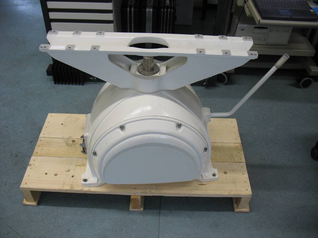
Click to zoom
Application Details
- Equipment Class
- MRD - Marine Radar
- Date of Grant
- Aug 22, 2012
- Application Purpose
- Original Equipment
- Date of Application
- Aug 22, 2012
- Equipment Note
- Shipborne Radar
- Frequency Range
- 2900.00000000 - 3100.00000000
- Company
- Consilium Italy srl
- Country
- Italy
Documents & Files
Document Text
Text extracted from the exhibit documents filed with the FCC. Open a document above to read the original.
Users Manual
Up Mast S-Band Installation MAN-SRTSUP-001 Rev.1 9.1 CHAPTER 9 INSTALLATION 9.1 INTRODUCTION This chapter of the Technical manual can be used as a self-contained Installation Manual for the SRT Up Mast S-Band Radar System and 12 feet Antenna to. It contains necessary information, pictures and drawings to handle, assemble and install this unit as a part of the complete Radar Equipment. Actions how to prepare this unit for the Radar Equipment Setup Procedure are also described. 9.2 LAYOUT AND CONNECTION DIAGRAMS Up Mast S-Band Installation MAN-SRTSUP-001 Rev.1 9.2 9.2.1 Layout SRT S-Band Up Mast Up Mast S-Band Installation MAN-SRTSUP-001 Rev.1 9.3 9.2.2 Block diagram Selux ST radar display with SRT S-Ban d Up Mast radar sensor Up Mast S-Band Installation MAN-SRTSUP-001 Rev.1 9.4 9.2.3 General interconnection diagram of PCBs (standard v ersion) Up Mast S-Band Installation MAN-SRTSUP-001 Rev.1 9.5 9.2.4 General interconnection diagram of PCBs (version wi th SRT HEATER) Up Mast S-Band Installation MAN-SRTSUP-001 Rev.1 9.6 9.3 SPECIFICATIONS 9.3.1 Dimensions and weights (also see outline drawings) Width 654 mm Depth 478 mm Height 765 mm Weight with 12 ft antenna 75 + 50 kg Swing circle with 12 ft antenna 3620 mm 9.3.2 Required power Standard configuration 115÷220 VAC - 56÷60 Hz or 48VDC Transceiver only 80 W With 100 KN 350 W With 100 KN (HSC) 850 W Medium power cunsumption 30 kW / 12 SLP 170 W Medium power cunsumption 30 kW / 12 SLP (HSC) 280 W 9.3.3 Environmental data Operating temperature -25° °° °C / +55° °° °C As in IEC 60945 Storage temperature -25° °° °C / +70° °° °C As in IEC 60945 Relative humidity Up to 95% at + 40° °° ° As for IEC 60945 Vibrations As for IEC 60945 International Protection (IP) IP 66 Up Mast S-Band Installation MAN-SRTSUP-001 Rev.1 9.7 9.4 INSTALLATION 9.4.1 Installation principles In order to obtain the best radar performance and accessibility, the following precautions should be used: - Space for the antenna to swing freely. See par.9.2 (Specifications; Antenna type) - Safety and easy access for maintenance purposes. It is preferable to use a platform on the ship mast. - The antenna to be accessible in all directions - Avoid exposure to exhaust fumes from the funnel - Avoid strong vibrations - Avoid interference between two antennas - Avoid obstacles in the radar beam, especially ahead of athwart ships directions If two radar sets are installed, their antennas should be installed on different levels. The antennas can be mounted, either on a single mast construction, so they are on top of each-other or the antennas can be mounted on a platform, one on portside and one on starboard side. The following formula and drawing, will help you to determine the correct distance and height between the two radar antennas. The 45° angle on the drawing is the actual vertical beam-width with a safety margin included. Example: “H = L”, H = height between the two antennas L = the distance between the two antennas If the distance L is 6m, then the height should be = 6m. Blind sectors towards the bow and within a few degrees on port and/or starboard side caused by the structure of the ship must be avoided with great care. In case of a blind sector at the bow in mid-ships’ position, it is advisable to mount the antennas on the starboard side of the ships’ keel-line. When obstacles are sufficiently far from the antenna, they will result in a blind sector on the radar display with approximately the same amplitude as observed by the human eye, but these obstacles can produce false echoes. An echo produced by an obstacle close to the antenna, can be suppressed by reflecting the antenna-beam skywards by mounting a reflector made of metal. This solution however does not eliminate the blind sector, but will reduce false echoes produced by the obstacle. The best position for the reflector can be found by testing out different positions. Up Mast S-Band Installation MAN-SRTSUP-001 Rev.1 9.8 It is highly recommended that the shipyard submit the drawings of the radar antenna position(s) to the manufacturer for approval. The Installation consists of following basic steps: - Mount the Unit without the Antenna on the mast - Make relevant connector - Install and connect the Performance Monitor (optional) arm - Install the Safety Switch - Mount the Antenna on the Unit NOTE The transceiver should be installed in such way that the performance monitor arm is not facing funnels or other big ships obstruction. Sector blanking is enabled to prevent false echoes caused by funnels and/or big ships construction (see above). If performance monitor arm is positioned, within this blanking area, the pedestal must be turned because the radar performance monitor is not working where there is no transmission in the sector of its sensor Installation of Safety Switch CHANGE: IT IS ON THE DC CORE OR ADAPTER BOX OR OPTIONAL FOR THE ADAPTER BOX EXTERNAL is compulsory. It is recommended to be installed at the bottom of the stairs giving access to the Antenna Pedestal. The waterproof switch is supplied by manufacturer, but a connection cable (2x2,5mm2) should be provided by the shipyard. The Antenna Group must be covered by plastic sheet during any painting performed after the installation. NOTE In no case, the Antenna shall be used to hoist the Pedestal up the mast Up Mast S-Band Installation MAN-SRTSUP-001 Rev.1 9.9 9.4.2 Mechanical installation The SRT consists of following units and type designations: Pedestal with 30 kW transceiver UP MAST/S-001 12 feet antenna ANT12LP/S-001 Safety switch (optional, always included in DC-CORE or SRT ADAPTER BOX) 9.4.2.1 Unit (Pedestal + Transceiver) The pedestal should be mounted with its lid hinges pointed forward and cable glands pointed astern. However the antenna swinging plane must be horizontal in all directions when ship is upright on even keel. Consider giving ample space for service, especially astern of the antenna group. If such space can not be achieved, contact manufacturer…
Text truncated - open the document above for the full version.
Users Manual
Up Mast S-Band General Information and Safety Precautions MAN-SRTSUP-001 Rev.1 1.1 CHAPTER 1 GENERAL INFORMATION AND SAFETY PRECAUTIONS 1.1 SAFETY PRECAUTIONS The equipment is equipped with fuses protecting the electronics devices from short circuits, which may damage the equipment or cause fires. Depending upon the material to be highlighted, the following attention letter headings are used in the technical manual content. DANGER BEFORE TURNING ON THE RADAR, MAKE SURE THAT THERE IS NO PERSONNEL NEAR THE ANTENNA. WARNING THE ELECTRONICS OF THE EQUIPMENT ARE SUPPLIED WITH THE MAINS POWER, ALSO WHEN THE EQUIPMENT IS SWITCHED OFF. FOR THIS REASON, OPENING A UNIT MUST BE PERFORMED ONLY BY SKILLED PERSONNEL. WARNING AN OPERATING OR MAINTENANCE PROCEDURE, PRACTICE, CONDITION AND STATEMENT WHICH, IF NOT STRICTLY OBSERVED, COULD RESULT IN INJURY OR DEATH OF PERSONNEL. WARNING AN OPERATING OR MAINTENANCE PROCEDURE, PRACTICE, CONDITION AND STATEMENT WHICH, IF NOT STRICTLY OBSERVED, COULD RESULT IN DAMAGE TO, OR DESTRUCTION OF, UNIT OR LOSS OF EMISSION EFFECTIVENESS. NOTE An essential operating or maintenance procedure, condition or statement which must be highlighted. Up Mast S-Band General Information and Safety Precautions MAN-SRTSUP-001 Rev.1 1.2 When a precaution is required which relates specifically to a part of the technical manual contents, the information is given in the relevant part of the manual. Warning and Cautions precede applicable text. 1.1.1 High voltage Radar equipment requires the use of high voltages. This can cause injury, or loss of life. Danger exists only when the units are opened, exposing internal circuits, as when servicing the equipment. You do not face any danger during normal operation. The SRT S-Band Radar System has been carefully designed to protect personnel from possible injury from high voltages at normal operation. When inspecting or servicing the equipment, nevertheless, it is recommended that the Line Switch to left open, as an added protection. Although every effort has been made to eliminate danger to personnel, no responsibility is accepted for any injury or loss of life suffered in connection with the equipment. 1.1.2 Safety switch The Radar Unit is provided with a safety switch, which disable the Antenna movement during maintenance operations and avoids high voltage damage. Always turn the safety switch off, whenever advised in this manual (for instance, before performing any maintenance or installation procedure). Ignoring safety switch operation may produce hazard of electrocution as well as other severe injures. 1.1.3 Safety precautions Purpose The safety precautions described in this paragraph are applicable to Up Mast S-Band. Depending upon the material to be highlighted, the following attention letter headings are used in the technical manual content. NOTE An essential operating or maintenance procedure, condition or statement which must be highlighted. Whenever a precaution, relating specifically to a part of the technical manual is needed, the information is given in the relevant part of the manual. Warnings and Cautions precede applicable text. Safety Operations During normal operation (front cover closed), the unit can be quickly disconnected from the main power line, setting to OFF the relevant circuit breaker located on the electric switchboard. During maintenance (front cover opened) it is possible to turn-on the unit by setting to SERVICE MODE the SW2 switch, mounted on the RTM Supply Assy. This switch is connected in parallel with the relay, controlled by the POWER ON command, and during normal operation must be set to Up Mast S-Band General Information and Safety Precautions MAN-SRTSUP-001 Rev.1 1.3 NORMAL. During maintenance, in order to prevent RTM occasional turning-on it is better to disconnect and insulate, momentarily, PWON terminal from the relevant terminal board. NOTE Main power line is always present on terminal board and on fuses. Safety Summary The following are general safety precautions that are not related to any specific procedure and therefore do not appear elsewhere in this technical manual. These are recommended precautions that personnel must understand and apply during most phases of operation and maintenance. KEEP AWAY FROM LIVE CIRCUIT Operating personnel must at all times observe all safety regulations. Do not replace components or make adjustments inside the unit with the high voltage supply turned ON. Under certain conditions, dangerous potentials may exist when the power breaker is in the OFF position, also due to charges retained by capacitors. To avoid casualties, always remove power and discharge to ground a circuit before touching it. DO NOT SERVICE OR ADJUST ALONE Under no circumstances should any person initiate servicing or adjusting the unit except in the presence of someone capable of helping help. RESUSCITATION Personnel working with or near high voltage should be familiar with modern methods of resuscitation. Such information may be obtained from the Bureau of Medicine and Surgery. Warning Information The following warnings appear in the text of this technical manual, and are repeated here for emphasis. WARNING USE EXTREME CARE WHEN WORKING ON THE UNIT ONCE THE COVER HAS BEEN OPENED. THE MAGNETRON ASSEMBLY OPERATES AT VOLTAGES THAT MAY PROVE FATAL. WARNING BEWARE OF HIGH VOLTAGE CAPACITORS. IT IS NECESSARY TO SHORT- CIRCUIT THEIR LEADS BEFORE PERFORMING ANY MAINTENANCE ACTION ON THEM. WARNING ON THE ELECTRIC SWITCHBOARD, SET TO OFF THE POWER BREAKER DEDICATED TO THE PRESENT EQUIPMENT AND HANG TO IT A PLACARD READING: “WORK IN PROGRESS-DO NOT SWITCH ON”. Up Mast S-Band General Information and Safety Precautions MAN-SRTSUP-001 Rev.1 1.4 WARNING USE EXTREME CARE WHEN WORKING ON THE EQUIPMENT ONCE THE FRONT COVER HAS BEEN OPENED. THE MAGNETRON ASSEMBLY OPERATES AT VOLTAGES THAT MAY PROVE FATAL. WARNING SET MAIN LINE BREAKER TO OFF BEFORE REPLACING ANY FUSE. FUSES ARE UNDER VOLTAGE LEVELS WHICH MAY PROVE …
Text truncated - open the document above for the full version.
Cover Letter(s)
1/1 CONFIDENTIALITY REQUEST for Certification Service in USA Federal Communication Commission Equipment Authorization Division, Application Processing Branch 7435 Oakland Mills Road Columbia, MD 21048 13/6/2012 TO WHOM IT MAY CONCERN Pursuant to Paragraphs §0.457 and 0.459 of the Commission’s Rules (47 C.F.R.) and Section §552(b)(4) of the Freedom of Information Act, we requests confidentiality for the following products: FCC ID Model name OD4-UPMASTS002 UP MAST/S-002 For the product stated above, we request permanent confidentiality for exhibits which contain Operational Description, Block Diagram, Schematics, Parts Lists or Tune Up Information. The above exhibits contain our trade secrets and proprietary information that could be of benefit to our competitors. If you have any questions, please feel free to contact me at the address shown below. Sincerely, Name: Alberto Baroncelli Company: Consilium Italy srl Address: Via Romita 26, Montagnana V.P. Florence (Italy) Phone: +39-0571-68121 Fax: +39-0571-670645 Email: [email protected]
External Photos
Test report no.: 1-3423/11-01-14 2012-08-08 Page 85 of 96 Annex E External photographs of the EUT Photo No. 1: Test report no.: 1-3423/11-01-14 2012-08-08 Page 86 of 96 Photo No. 2: Photo No. 3: Test report no.: 1-3423/11-01-14 2012-08-08 Page 87 of 96 Photo No. 4: Photo No. 5: transceiver in-/output, antenna connector
ID Label/Location Info
Ç Consilium Pag. 3 of 4 Montagnana Val di Pesa - 12/06/2012 Equipment Unit Type : FCC ID : IC ID : USCG SRT S-BAND UPMAST HSC UPMAST/S-002 OD4-UPMASTS002 10417A -UPMASTS002 165.120/EC0735/4340779 Label sample: 52 mm 105 mm FCC ID: OD4-UPMASTS002 IC ID: 10417A - UPMASTS002 Ç Consilium Pag. 4 of 4 Montagnana Val di Pesa - 12/06/2012 Location of the labels: Equipment Unit Type : SRT S-BAND UPMAST UPMAST/S-001 SRT S-BAND UPMAST HSC UPMAST/S-002 LABEL
Internal Photos
Test report no.: 1-3423/11-01-14 2012-08-08 Page 88 of 96 Annex F Internal photographs of the EUT Photo No. 1: motor side Photo No. 2: Test report no.: 1-3423/11-01-14 2012-08-08 Page 89 of 96 Photo No. 3: magnetron side Photo No. 4: rotation sensor Test report no.: 1-3423/11-01-14 2012-08-08 Page 90 of 96 Photo No. 5: magnetron, circulator, limiter and receiver Photo No. 6: magnetron with RF-filter Test report no.: 1-3423/11-01-14 2012-08-08 Page 91 of 96 Photo No. 7: magnetron Photo No. 8: magnetron Test report no.: 1-3423/11-01-14 2012-08-08 Page 92 of 96 Photo No. 9: magnetron, type label Photo No. 10: circulator and limiter Test report no.: 1-3423/11-01-14 2012-08-08 Page 93 of 96 Photo No. 11: receiver Test report no.: 1-3423/11-01-14 2012-08-08 Page 94 of 96 Photo No. 12: external power supply Photo No. 13: Test report no.: 1-3423/11-01-14 2012-08-08 Page 95 of 96 Photo No. 14:
Test Report
2012-08-08 Page 1 of 96 TEST REPORT Test report no.: 1-3423/11-01-14 Testing laboratory Applicant CETECOM ICT Services GmbH Untertuerkheimer Strasse 6 – 10 66117 Saarbruecken / Germany Phone: + 49 681 5 98 - 0 Fax: + 49 681 5 98 - 9075 Internet: http://www.cetecom.com e-mail: [email protected] Accredited Testing Laboratory: The testing laboratory (area of testing) is accredited according to DIN EN ISO/IEC 17025 (2005) by the Deutsche Akkreditierungsstelle GmbH (DAkkS) The accreditation is valid for the scope of testing procedures as stated in the accreditation certificate with the registration number: D-PL-12076-01-01 Area of Testing: Radio/Satellite Communications Consilium Italy S.r.l. Via Romita 26 50025 Montagnana V.P. Montespertoli / ITALY Phone: +39 05 71 68 12 1 Contact: Albertoi Baroncellii e-mail: [email protected] Phone: +39 05 71 68 12 71 Manufacturer Consilium Italy S.r.l. Via Romita 26 50025 Montagnana V.P. Montespertoli / ITALY Test standard/s CFR 47 Part 80 Stations in the maritime services For further applied test standards please refer to section 4 of this test report. Test Item Kind of test item: Shipborne Radar - S-Band Up Mast Transceiver Model name: UP MAST/S-002 FCC ID: OD4-UPMASTS002 Frequency range: 2.9 - 3.1 GHz Tx power conducted: 30 kW Power Supply: 100 - 240 V AC Temperature Range: 0°C to +50°C This test report is electronically signed and valid without handwriting signature. For verification of the electronic signatures, the public keys can be requested at the testing laboratory. Test report authorised: Test performed: Karsten Geraldy Meheza Walla Senior Testing Manager Expert Test report no.: 1-3423/11-01-14 2012-08-08 Page 2 of 96 1 Table of contents 1 Table of contents............................................................................................................................................2 2 General information .......................................................................................................................................3 2.1 Notes and disclaimer ..........................................................................................................................3 2.2 Application details...............................................................................................................................3 3 Test location ...................................................................................................................................................3 4 Test standard/s and Reference/s ..................................................................................................................4 5 Test environment............................................................................................................................................4 6 Test laboratory/ies sub-contracted ..............................................................................................................4 7 Test item ..........................................................................................................................................................5 7.1 General Description ............................................................................................................................5 7.2 List of components .............................................................................................................................5 7.3 Antenna system(s) ..............................................................................................................................5 7.4 Operating conditions ..........................................................................................................................5 7.5 Additional information ........................................................................................................................5 8 RF measurements ..........................................................................................................................................6 8.1 Description of test setup ....................................................................................................................6 8.1.1 Conducted measurements..........................................................................................................6 8.1.2 Radiation measurements............................................................................................................7 8.2 Test environment...............................................................................................................................10 8.3 Measurement uncertainties ..............................................................................................................10 9 Test results ...................................................................................................................................................11 9.1 Summary ............................................................................................................................................11 9.2 Overview.............................................................................................................................................12 Annex A Measurement results, part 1 .........................................................................................................20 Annex B Measurement results, part 2 .........................................................................................................24 Annex C Test equipment and ancillaries used for tests ...........................................................................81 Annex D Photographs of the test setup ......................................................................................................82 Annex E External photographs of the EUT.................................................................................................85 Annex F Internal photographs of the EUT ................................…
Text truncated - open the document above for the full version.
Contact Information
Applicant
Alberto Baroncelli(R&D Manager)
Test Firm
cetecom advanced GmbHGerald Schmidt
Technical Specifications
| # | Rule Parts | Frequency Range | Power Output | Emission | Tolerance |
|---|---|---|---|---|---|
| 1 | 80 | 2.90 GHz - 3.10 GHz | 30000 W | 65M1P0N | 534.0000000000 ppm |