Text extracted from the exhibit documents filed with the FCC. Open a document above to read the original.
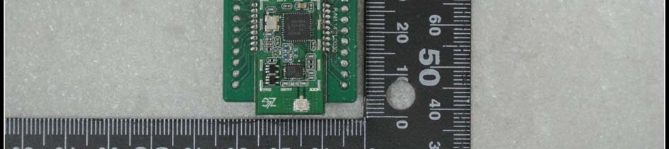
ZM2410P0-ATS User Manual Date: 2012/05/18 V1.00 Guangzhou ZHIYUAN Electronics Stock Co., Ltd. www.zlg.cn Item Contents Terms Zigbee module, ZM2410P0-ATS Abstract This document mainly describes the hardware and usage of the ZM2410P0-ATS Zigbee module. Zigbee Wireless Network Module Specification User Manual ©2012 Guangzhou ZHIYUAN ElectronicsDate: 2012/05/18 User Manual V1.00 ZM2410P0-ATS Guangzhou ZHIYUAN Electronics Stock Co., Ltd. Zigbee Wireless Communication Module i R R e e v v i i s s i i o o n n H H i i s s t t o o r r y y Version Rev. Date Modifications V1.00 2012-05-18 Original version V1.00 2012-05-18 Translated to English ©2012 Guangzhou ZHIYUAN ElectronicsDate: 2012/05/18 User Manual V1.00 ZM2410P0-ATS Guangzhou ZHIYUAN Electronics Stock Co., Ltd. Zigbee Wireless Communication Module ii C C o o n n t t e e n n t t s s Chapter 1: Overview .................................................................................... 1 Chapter 2: Hardware .................................................................................... 3 2.1 Physical size ....................................................................................................... 3 2.2 Specification of pins .......................................................................................... 4 2.3 Hardware parameters ........................................................................................ 5 Chapter 3: Configuration & Upgrade .......................................................... 6 3.1 Local configuration and upgrade ..................................................................... 6 3.1.1 Get configuration parameters ................................................................................... 6 3.1.2 Modify configuration parameters ............................................................................. 7 3.1.3 Firmware Upgrade ................................................................................................... 8 3.2 On air remote configuration and upgrade ....................................................... 9 3.2.1 Get configuration parameters ................................................................................... 9 3.2.2 Change parameter settings ..................................................................................... 10 3.2.3 Firmware upgrade .................................................................................................. 10 Chapter 4: Configuration Commands ...................................................... 11 Chapter 5: FAQ & Answers ........................................................................ 12 ZM2410P0-ATS Guangzhou ZHIYUAN Electronics Stock Co., Ltd. Zigbee Wireless Communication Module ©2012 Guangzhou ZHIYUAN ElectronicsDate: 2012/05/18 User Manual V1.00 1 C C h h a a p p t t e e r r 1 1 : : O O v v e e r r v v i i e e w w ZM2410P0-ATS is a 2.4GHz low power Zigbee module developed by Guangzhou ZHIYUAN Electronics Stock Co., Ltd. It integrates complex RF circuit to a compact size board and provides built-in communication protocol in its 8051 core. The transmission protocol of it is fully transparent to user; it provides support to the remote on-air firmware upgrade and remote module configuration. ZM2410P0-ATS module can save user’s development time on wireless communications, further reduce the time to market of user’s products, make them more competitive to others. Figure 1-1: Photo of ZM2410P0-ATS module For different application field, the module has different communication protocols. The factory default protocol is P2P (Point-to-Point) protocol. Table 1-1: Communication Protocols Protocol Name Features Notices Point-to-Point (P2P) ZLG Supports point-to-point, point-to-multipoint wireless communication Factory default Wireless networking ZLGNET Supports up to 20 levels of router, wireless peer-to-peer network; example application: street lamp controller Wireless voice ZLGV Supports wireless voice transmission The protocol described in this document is P2P communication protocol, if user wants to know more about the ZLGNET communication protocol, please download the ZM2410P0-ATS Guangzhou ZHIYUAN Electronics Stock Co., Ltd. Zigbee Wireless Communication Module ©2012 Guangzhou ZHIYUAN ElectronicsDate: 2012/05/18 User Manual V1.00 2 Zigbee peer-to-peer wireless network communication protocol firmware ZLGnet document on our website. ZM2410P0-ATS Guangzhou ZHIYUAN Electronics Stock Co., Ltd. Zigbee Wireless Communication Module ©2012 Guangzhou ZHIYUAN ElectronicsDate: 2012/05/18 User Manual V1.00 3 C C h h a a p p t t e e r r 2 2 : : H H a a r r d d w w a a r r e e This chapter describes the hardware of ZM2410P0-ATS. 2.1 Physical size Figure 2-1: Physical size of ZM2410P0-ATS ZM2410P0-ATS Guangzhou ZHIYUAN Electronics Stock Co., Ltd. Zigbee Wireless Communication Module ©2012 Guangzhou ZHIYUAN ElectronicsDate: 2012/05/18 User Manual V1.00 4 2.2 Specification of pins Figure 2-2 shows the pin assignment of ZM2410P0-ATS Figure 2-2: Pin assignments Table 2-1: Specification of pins Pin # Name Description 1 VCC Power input 2 TXD UART Transmit pin 3 RXD UART Receive pin 4 NC Reserved 5 #REST Rest Pin, active low pin 6 NC Reserved 7 NC Reserved 8 ISP Short to VCC to enter ISP upgrade mode (factory upgrade only) 9 #SLEEP Sleep mode, active low pin 10 GND Power Grounding 11 NC SPI data input 12 NC Reserved 13 NC Reserved 14 NC Reserved 15 NC Reserved 16 NC Reserved 17 NC Reserved 18 NC Reserved 19 NC Reserved 20 NC Reserved ZM2410P0-ATS Guangzhou ZHIYUAN Electronics Stock Co., Ltd. Zigbee Wireless Communication Module ©2012 Guangzhou ZHIYUAN ElectronicsDate: 2012/05/18 User Manual V1.00 5 2.3 Hardware parameters Table 2-2: Hardware parameters Description ZM2410P0-ATS Unit Min. Typ. Max. Power supply 5.0 - 5.5 V Frequency Range 2.405 - 2.480 GHz Receive sensitivity (1% PER) - -97 -99 dBm Transmit power 5.5 6 7 dBm Link budget - 103 - dBm Working bandwidth - 5.0 - MHz Wireless output rate - 250 1…
Text truncated - open the document above for the full version.
Request for Modular Approval FCC ID: ODH‐ZMATS Item Requirements EUT 1 Have its own RF shielding Device is equipped with metal shielding to cover RF section. Refer to external and internal photos. 2 Have buffered modulation/data inputs (if such inputs are provided) All inputs to the modules are buffered through logic and microprocessor inputs 3 Have its own power supply regulation The module was powered by Host, using 3.3VDC power. 4 Meet the antenna requirements of section 15.203 The device was used fixed antenna, the antenna was welding on the module. 5 Demonstrate compliance in a stand‐alone configuration Device is tested in a test fixture in a standalone configuration. Refer to exhibit “Test Setup Photos”. 6 The licensed module must have a FCC ID label on the module itself. That FCC ID label must be visible through a window on the final device or it must be visible when an access panel, door or cover is easily removed. If not, a second label must be placed on the outside of the final device that contains the following text: Contains “FCC ID: ODH‐ZMATS” FCC ID label format will be included in the filling. Host ID label will be displayed on the host system. 7 The module must comply with all specific rules applicable to the transmitter. The grantee must provide comprehensive instructions to explain compliance requirements. Please refer to “User Manual” Exhibit 8 The module must comply with RF exposure requirements. See FCC Rules. Spread Spectrum transmitters must comply with RF exposure limits in 15.247. Compliance with RF exposure requirements is addressed in RF exposure report (MPE).
External Photos 1. Test board with EUT full view 2. EUT Top view 3. EUT Bottom View
FCC ID: ODH-ZMATS Label Label Material: Adhesive Bond Paper Letter Color: Black Background Color: White Label Location
Internal Photos 1. EUT without shielding Top View 2. EUT without shielding Bottom View
Antenna TQX-2400AIL Tech. Spec. Frequency Range-MHz 2400~2483 Bandwidth-MHz 83 Gain-dBi 2.15 VSWR ≤1.5 Nominal Impedance-Ω 50 Polarization vertical Maximum Power-W 50 Dimensions-mm 120 Weight-kg 0.02 天线方向图 天线驻波图
FCC ID: ODH‐ZMATS Page 1 of 2 Prediction of MPE limit at given distance Product Description: ZM2410P0-ATS Low Power Zigbee Module Type: ZM2410P0-ATS 1. Introduction Equation from page 18 of OET Bulletin 65, Edition 97-01 Where: S = power density P = power input to the antenna G = power gain of the antenna in the direction of interest relative to an isotropic radiator R = distance to the center of radiation of the antenna 2. Limits for Maximum Permissible Exposure According to FCC Part 1.1307, systems operating under the provisions of this section shall be operated in a manner the ensures that the public is not exposed to radio frequency energy level in excess of the commission’s guidelines. According to FCC Part 1.1310 RF exposure is calculated. Limits for General Population/ Uncontrolled Exposure Limits for General Population/ Uncontrolled Exposure Frequency Range (MHz) Electric Field Strength(E)(V/m) Magnetic Field Strength (H)(A/m) Power Density (S)(mW/cm 2 ) 0.3-1.34 614 1.63 (100)* 1.34-30 824/f 2.19/f (180/f2)* 30-300 27.5 0.073 0.2 300-1500 f/1500 1500-100,000 1.0 FCC ID: ODH‐ZMATS Page 2 of 2 3. Test result 2.4G Band Maximum peak output power at antenna input terminal(dBm): 5.92 Maximum peak output power at antenna input terminal(mW): 3.91 Source-based time-averaged output power: -- Prediction distance(cm): 20 Predication frequency(MHz): 1942.5 Antenna Gain (typical) (dBi): 2.15 Power density at predication frequency at 20 cm(mW/cm 2 ): 0.001 MPE limit for RF exposure at prediction frequency(mW/cm 2 ): 1.0 4. Conclusion this EUT is deemed to comply with the reference levels are met, then the basic restrictions will be complied with human exposure limits.
SZ12050110W02 Page 2 of 30 DIRECTORY 1. GENERAL INFORMATION .................................................................................................... 3 1.1. EUT Description ....................................................................................................................... 3 1.2. Test Standards and Results ........................................................................................................ 4 1.3. Facilities and Accreditations ..................................................................................................... 5 2. 47 CFR PART 15C REQUIREMENTS .................................................................................... 6 2.1. Peak Output Power.................................................................................................................... 6 2.2. Bandwidth ................................................................................................................................. 8 2.3. Conducted Spurious Emissions ............................................................................................... 11 2.4. Power spectral density (PSD) ................................................................................................. 13 2.5. Band Edge ............................................................................................................................... 16 2.6. Conducted Emission ............................................................................................................... 20 2.7. Radiated Emission................................................................................................................... 23 Change History Issue Date Reason for change 1.0 July 13, 2012 First edition SZ12050110W02 Page 3 of 30 1. General Information 1.1. EUT Description EUT Type ............................. : Zigbee Module Serial No. .............................. : (n.a, marked #1 by test site) Hardware Version ................. : V1.01 Software Version .................. : Applicant .............................. : Manufacturer ........................ : V1.08 Guangzhou ZHIYUAN Electronics Stock Co.,Ltd. Floor 2.Building No.7,Huangzhou Industrial Estate, Chebei Road, Tianhe District, Guangzhou City, CHINA. Guangzhou ZHIYUAN Electronics Stock Co.,Ltd. Floor 2.Building No.7,Huangzhou Industrial Estate, Chebei Road, Tianhe District, Guangzhou City, CHINA. Frequency Range .................. : 2.405GHz - 2.480GHz (at interval of 5MHz) Channel Number................... : 16 Modulation Type .................. : DSSS Antenna Type ........................ : Dipole Antenna Antenna Gain ........................ : 2.15dBi Note 1: The EUT is a Zigbee Module, with IEE802.15.4. Only DSSS Modulation technology was tested in this report. Note 2: The frequencies allocated is F (MHz) =2405+5*(n-1) (1<=n<=16). The lowest, middle, highest channel numbers of the EUT used and tested in this report are separately 1 (2405MHz), 6 (2440MHz) and 11 (2480MHz). Note 3: For a more detailed description, please refer to Specification or User’s Manual supplied by the applicant and/or manufacturer. SZ12050110W02 Page 4 of 30 1.2. Test Standards and Results The objective of the report is to perform testing according to 47 CFR Part 15 Subpart C (2.4GHz ISM band radiators) for the EUT FCC ID Certification: No. Identity Document Title 1 47 CFR Part 15 (10-1-09 Edition) Radio Frequency Devices Test detailed items/section required by FCC rules and results are as below: No. Section Description Result 1 15.247(a) Number of Hopping Frequency (n.a) 2 15.247(b) Peak Output Power PASS 3 15.247(a) Bandwidth PASS 4 15.247(a) Carrier Frequency Separation (n.a) 5 15.247(a) Time of Occupancy (Dwell time) (n.a) 6 15.247(c) Conducted Spurious Emission PASS 7 15.247(c) Band Edge PASS 8 15.207 Conducted Emission PASS 9 15.209 15.247(c) Radiated Emission PASS 10 15.247(d) Power spectral density (PSD) PASS The tests of Conducted Emission and Radiated Emission were performed according to the method of measurements prescribed in ANSI C63.4 2009. These RF tests were performed according to the method of measurements prescribed in KBD558074. SZ12050110W02 Page 5 of 30 1.3. Facilities and Accreditations 1.3.1. Facilities Shenzhen Morlab Communications Technology Co., Ltd. Morlab Laboratory is a testing organization accredited by China National Accreditation Service for Conformity Assessment (CNAS) according to ISO/IEC 17025. The accreditation certificate number is L3572. All measurement facilities used to collect the measurement data are located at FL.3, Building a, FeiYang Science Park, No.8 LongChang Road, Block 67, BaoAn District, ShenZhen, GuangDong Province, P. R. China. The test site is constructed in conformance with the requirements of ANSI C63.7, ANSI C63.4 and CISPR Publication 22; the FCC registration number is 741109. 1.3.2. Test Environment Conditions During the measurement, the environmental conditions were within the listed ranges: Temperature (°C): 15 - 35 Relative Humidity (%): 30 -60 Atmospheric Pressure (kPa): 86-106 SZ12050110W02 Page 6 of 30 2. 47 CFR Part 15C Requirements 2.1. Peak Output Power 2.1.1. Requirement According to FCC section 15.247(b)(3), For systems using digital modulation in the 902-928 MHz, 2400-2483.5 MHz, and 5725-5850 MHz bands: The maximum peak conducted output power of the intentional radiator shall not exceed 1Watt. 2.1.2. Test Description The measured output power was calculated by the reading of the Power Meter and calibration. A. Test Setup: The EUT (Equipment under the test) which is powered by the Control PC is coupled to the Power Meter; the RF load attached to the EUT antenna terminal is 50Ohm; the path loss as the factor is calibrated to correct the reading, all test result in power meter. B. Equipments List: Description Manufacturer Model Serial No. Cal. Date Cal. Due EPM Series Power Meter Agilent E4418B GB43318055 2012.05 2013.05 Attenuator Power meter Test boar…
Text truncated - open the document above for the full version.
Test Setup Photos 1. CE 2.RE
| # | Rule Parts | Frequency Range | Power Output |
|---|---|---|---|
| 1 | 15C | 2.40 GHz - 2.48 GHz | 4.00 mW |

Zigbee Module
Equipment Class
DTS - Digital Transmission System