ODXKLTKLT radio for alarm purposes, vehicle location (an
KAVlcomm Communications (PTY) Ltd.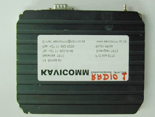
Click to zoom
Application Details
- Equipment Class
- LMS - Part 90 Location & Monitoring Transmitter
- Date of Grant
- Sep 21, 2000
- Application Purpose
- Original Equipment
- Date of Application
- Aug 16, 2000
- Equipment Note
- KLT radio for alarm purposes, vehicle location (an
- Frequency Range
- 450.00000000 - 470.00000000
- Country
- N/A
Documents & Files
Document Text
Text extracted from the exhibit documents filed with the FCC. Open a document above to read the original.
Users Manual
Communications (Pty) Ltd. KLT ALARM RADIO MANUAL December 1998 WARNING The RF POWER DEVICES BLU30/12 and M56649HR CONTAIN BERYLIUM OXIDE WHICH IS TOXIC. DO NOT TRY TO BREAK THEM OPEN. The Devices are Entirely Safe Provided they are not Physically Damaged. Table of contents Section Title 1. Introduction and Specifications. 1.1 Introduction 1.2 Specifications 2. Installation 2.1 General 2.2 Power Source 2.3 Antenna 3. Features and Operation Instructions 3.1 Features 3.2 Operation Instructions 4. Theory of Operation 4.1 Receiver 4.2 Transmitter 4.3 Controller 4.4 Synthesiser 5. Maintenance 5.1 RF Circuitry main Test Points and Alignment Locations 5.2 Controller Circuitry Test Points 5.3 Alignment Procedure 5.3.1 Synthesiser Alignment Procedure 5.3.2 Receiver Alignment Procedure 5.3.3 Transmitter Alignment Procedure 6. Schematic and Component Location Diagrams (Assembly) 6.1 Receiver Circuit Diagram 6.2 Transmitter Circuit Diagram 6.3 Controller Circuit Diagram 6.4 Synthesiser Circuit Diagram 7. Mechanical Assembly 7.1 Exploded View of Radio Assembly 8. Parts List 1.1 INTRODUCTION The KLT radio, which is also referred to as FMR (Fleet Management Radio), is designed for alarm purposes, vehicle location (and tracking) and fleet management. In contrast to “normal” mobile units KLT is not intended for speech processing. Data is transmitted by analogue tone FM modulation. Its compact size makes it ideal for the above applications. The unit may be operated on either standard MPT1327 system or on a Kavicomm proprietary system. 1.2 SPECIFICATIONS General Power Supply Operating Voltage : 10,8 to 15,6V DC. Antenna Impedance : 50Ω, unbalanced. Frequency Range : 450 – 470 MHz Channel Spacing : 12,5 MHz Modulation : FM Frequency Stability : ± 2,5 ppm (-30°C to 60°C) Dimensions : (142 L) x (115 W) x (27 H) mm Weight : 0,5 Kg Max. Channel Separation (Tx or Rx) : 14 MHz Receiver Sensitivity : -115 dm (typical), without de-emphasis fore 12db SINAD Hum and Noise Ratio : 34 dB Spurious Response and Image : 50 dB Conducted Spurious Emissions : Less than –60 dBm Transmitter Nominal RF Output Power : 15 watts Spurious Emissions and Harmonics : -75 dBC Adjacent Channel Power : -70 dBC Frequency Deviation : fixed at 1,5 KHz ± 1 dB Hum and Noise Ratio : 34 dB 2. INSTALLATION 2.1 General Radio placement in a vehicle is not critical to its performance. Because of its small size the radio could practically be installed almost anywhere. Do not install the unit where ambient temperatures could rise above +60°C. Choose a place where the main power cable will be as short as possible. 2.2 Power Source The radio operates from a 13.6V DC (6 Amp) source such as a standard automotive “12v” negative Gnd electrical system. In case a vehicle uses “24V” system it is recommended to use a proper DC to DC converter preferably a linear type (if possible) in order to avoid radio interference. The installer is advised to make sure that the vehicle’s battery is “healthy” and that it is not lower than 10,8V DC. A low battery or defective regulator can severely impair the unit’s operation. A power cable is supplied with the radio. The red wire must always be connected to the (+) terminal of the battery and the black to the (-) terminal. CAUTION Do not ever apply more than 16V to the radio. Check the voltage source before connecting the power leads to it. Do not connect the power leads to the cigarette lighter socket or to any other points where high spike voltages might develop. Do not install the unit in a positive GND vehicle. 2.3 Antenna The antenna and its coaxial cable are supplied by Kavicomm. The installer may install other antennae provided they are of equivalent quality or better. Bear in mind that the radio is designed to operate with a 50Ω antenna. 3. FEATURES AND OPERATING INSTRUCTIONS 3.1 Features The unit is a multipurpose one. The main purpose is raising alarm signals once activated by input at the Micro-Controller connector. The alarm data is transmitted using FFSK signals, which are decoded at the central control room or other similar means. In addition the unit could be used as a radio link repeating signals which are received by its receiver. Both of the above-described functions utilize either a standard MPT1327 network or Kavicomm’s proprietary network. The receiver is equipped with Relative Signal Strength Indication (RSSI) in order to facilitate locking on strongest (RF) signal available on the network. 3.2 Operating Instructions Once the radio is installed as per installation instructions (see section 2) the radio is turned on (no switch for turning the radio on is available). If a RF signal is available on the air to which the radio is programmed to receive, he unit locks on. The RSSI indication led will flash periodically. The more times the led flashes the stronger signal is being received. 5 flashes in a row indicate that the signal strength is stronger than – 80dMm. No more than 5 flashes are available even if the signal is very strong. When the led flashes only once the signal strength is around – 110dBm. If no signal is available the led flashes at a very low rate. As the unit has no other indications and/or knobs to operate the operation becomes very simplified. 4. THEORY OF OPERATION 4.1 Receiver The receiver is double heterodyne type having the 1 st I.F at 45MHz and 2 nd I.F at 455KHz. The receiver outputs two signals: (a) A DC voltage level which is relative to received signal strength and (b) FFSK signal which is composed of two tones 1200 and 1800Hz. Both of the above signals are fed to the Micro-controller circuitry for analysis and detection. The received signal, which comes from the antenna connector and flows via the Tx L.P.F. (harmonic trap), is applied via C 95 , C 97 , C 98 , C 100 , C 101 and C 103 to the base of the RF Front End Amplifier Q 25 . C 96 and L 25 form the first Front-End filter. So do the other components which follow with a similar arrangement. This amplifier provides some 15-dB ga…
Text truncated - open the document above for the full version.
Block Diagram
Receiver Block Diagram Receiver Block Diagram Description The received signal which comes via the L.P.F. in the Transmitter (Tx) goes via the Front End (F/E) Band pass filter to the RF F/E Amplifier. The total gain of the F/E filter and the F/E Amplifier is in the order of 12dB. The Amplifier’s signal is fed to the Mixer which is also fed the L.O. signal, the Mixer provides some 15dB gain as well as the difference between the incoming signal and the L.O. signal which is 45MHz. The x-tal Filter and IF amplifier filter the 45MHz signal and feed it to the IF chip which together with the quadrature tank circuit demodulate (recover) the audio tone signal. The difference of 455KHz is achieved by mixing inside the IF chip between the 45MHz incoming signal and the 45,455MHz x-tal oscillator which is also part of the IF chip. The demodulated tone signals pass through a Tchebeshef L.P.F circuit and is fed into a Modem circuit which is part of the Micro-controller. The I.F. chip produces also an RSSI (DC) signal which is also fed to the Micro-controller. received signal Front End Band Pass Filter F/E AMP Mixer L.O. signal (45MHz below Rx-d signal) X-tal Filter and IF Amp 45,455MHz I.F. Chip RSSI DC AMP RSSI O/P to Micro-Controller RSSI Quadrature Tank (455KHz) + Tchebeshef L.P.F. (2,5KHz) Demodulated signal to Modem in Micro-controller ~ ~ ~ Transmitter Block Diagram Transmitter Block Diagram Description The transmitter consists of 3 RF amplifiers. The 1 st RF Amplifier amplifies the +6dBm incoming drive signal to a level of approx. +16dBm. The amplified signal passes through the RF Attenuator diode and feeds the RF Module (type M67749HR). This in turn produces a level of 5 to 7W of RF output. This signal is fed to the RF Power Amplifier via a matching line (Micro-strip). The RF power amplifier, which is capable of transmitting up to 20W, amplifies the signal to the desired level. As the radio is specified as a 15watts device, it is set so at the factory by the set ref. voltage/level potentiometer (top right-hand side of diagram). The current at the 50Ω line is sampled (sensed) by the RF sampling diode which produces a DC voltage relative to the O/P power this DC is compared to the Set Ref. Voltage by the ALC Opamp which in turn biases the RF attenuator diode, thus setting the O/P to 15W. The received signal flows via the LPF (Harmonic Trap) to the switching and protection circuitry and the fed to the Rx F/E (BLU30/12) AMP RF Power RF +BBias (MRF5711LT1) Diode ATTN. +16dBm Drive L.O. Tx +6dBm RF IN 1st RF AMP 5-7W 5-7W (M67749HR) RF Module Matching line 1,0A Max +B RF Switch 15W Matching line 5A Max. Diode F/E To Rx & protec. Switching L.P.F. (Harmonic trap) voltage Set ref. filtering circuitry DC Coupling & - Sampling RF Automatic Level OP-AMP Control (ALC) + + R To Antenna 50Ω LINE Circuitry General Block Diagram General Description of Block Diagram The KLT Alarm radio is controlled by its Micro-Controller. The radio could work in one of the following modes: a) On a fixed channel. b) On a group of channels, choosing the strongest one (by using its RSSI facility) and locking on it. Depending on the way it is programmed the radio can operate on either mode a or b but not both. The Micro-controller may be connected to an external device to receive a command or to deliver a command to that external device. The commands are DC signals of either high (5V) or low (0V) voltages. The same I/O port serves also for programming the KLT. The Freq. Synthesizer receives a command from the Micro-Controller as to what frequencies (for L.O. Injection and Tx Drive) it should produce. The Micro-Controller circuitry also produces the Modulating (tone) signal which is responsible for the modulation of the Tx VCO. This modulation is of Analogue Frequency type. The modulating signal can be either 1200Hz tone or 1800Hz. No other tone frequency is used. The frequency deviation is always fixed at 1,5KHz ± 1dB. In addition the Micro-controller receives a demodulated tone of the above freq. (i.e. 1200Hz or 1800Hz) and outputs a command at the I/O port. The transmitter is driven by the L.O. Tx drive signal which is of the order of 6-8dBm. The Tx produces a signal of 15W maximum, this signal passes through the low pass filter (LPF) which acts as a harmonic suppressor (trap). Thus delivering a “clean” signal with harmonic content of less than –70dBC. The receiver signal passes through the Tx LPF and arrives at the its Front End. The receiver outputs the demodulated signal which goes to the Micro-Controller. Frequency Synthesiser Receiver LPF Antenna 0dB Micro-Controller Transmitter I/O to/from External Device L.O. Injec. L.O. Drive Demodulated signal Modulated signal Micro-Controller Block Diagram Micro-Controller Block Diagram Description The Micro-controller part of the KLT includes the above shown three main blocks the Micro-processor IC HD6303XF (U6) the FFSK Tone Modem (U4) and the LATCH IC (U5). The Micro-Processor IC receives the commands as to when to transmit an alarm signal and to what frequency the synthesiser must be locked on. The Processor can also raise an alarm DC level at the I/O port depending on the mode that the programming was done for. The Micro-Processor also receives the RSSI (DC) signal via an A/D device (U3) this allows it to choose a better off-the-air signal if available. The FFSK Tone Modem outputs the tones-modulating signal-to directly (analog) modulate the Tx VCO in Synthesiser. In order to save energy the radio can be “put to sleep” by using the Radio Disable (DC) command which is sent to IC U23 via the LATCH U5 in the Micro-Controller part of the KLT. U14 FFSK Tone Modem U5 74HC256 A/D U3 LATCH RF Enable (To Synthesiser) Radio Disable (to IC U23) RSSI (from Rx) HD6303XF Micro-Processor IC U6 Synthesiser Clock Synthesiser Data Synthesiser LE 7,3MHz 4,032MHz Modulating Signal to Frequency Synthesiser I/O Ports Synthesiser Block Diagram Synthesiser Block Diagram Description The function of the fre…
Text truncated - open the document above for the full version.
Cover Letter(s)
14 Simba Street Sebenza 1610 Communications (Pty) Ltd P.O. Box 8770 Reg. No. 87/01887/07 Edenglen 1613 South Africa RESEARCH, DESIGN, DEVELOPMENT & MANUFACTURE OF COMMUNICATIONS EQUIPMENT Tel:(011)452-4146/7/8/9 Fax:(011)452-3209 E-mail:[email protected] Website:www.kavicomm.qc.co August 17, 2000 FEDERAL COMMUNICATIONS COMMISSION EQUIPMENT APPROVAL SERVICES P.O.B. 358315 Pittsburgh, PA 15251-5315 USA Subject: Application for certification of KLT Alarm Radio KLT-45, FCC ID: ODXKLT Dear Gentlemen, Please find attached our application for certification of KLT Alarm Radio KLT-45, FCC ID: ODXKLT, prepared in accordance with FCC Rules, parts 2 and 90. The product testing and this application for certification were performed by Hermon Laboratories, which is listed by FCC. Hermon Labs responsible person is Dr. Edward Usoskin, tel: 01197266288001, fax:01197266288277, e-mail: [email protected] We hope this application satisfies your requirements. Sincerely yours, A.EMANUEL DIRECTOR DIRECTORS: I.Katz, A.Emanual
External Photos
Top view Bottom view Connectors
ID Label/Location Info
S/N. FCC ID: ODXKLT
Internal Photos
PCB component side PCB printed side
Operational Description
The KLT radio, which is also referred to as FMR (Fleet Management Radio), is designed for alarm purposes, vehicle location (and tracking) and fleet management. In contrast to “normal” mobile units KLT is not intended for speech processing. Data is transmitted by analogue tone FM modulation. Its compact size makes it ideal for the above applications. The unit may be operated on either standard MPT1327 system or on a Kavicomm proprietary system. SPECIFICATIONS General Power Supply Operating Voltage : 10,8 to 15,6V DC. Antenna Impedance : 50Ω, unbalanced. Frequency Range : 450 – 470 MHz Channel Spacing : 12,5 MHz Modulation : FM Frequency Stability : ± 2,5 ppm (-30°C to 60°C) Dimensions : (142 L) x (115 W) x (27 H) mm Weight : 0,5 Kg Max. Channel Separation (Tx or Rx) : 14 MHz Receiver Sensitivity : -115 dm (typical), without de-emphasis fore 12db SINAD Hum and Noise Ratio : 34 dB Spurious Response and Image : 50 dB Conducted Spurious Emissions : Less than –60 dBm Transmitter Nominal RF Output Power : 15 watts Spurious Emissions and Harmonics : -75 dBC Adjacent Channel Power : -70 dBC Frequency Deviation : fixed at 1,5 KHz ± 1 dB Hum and Noise Ratio : 34 dB 2. INSTALLATION 2.1 General Radio placement in a vehicle is not critical to its performance. Because of its small size the radio could practically be installed almost anywhere. Do not install the unit where ambient temperatures could rise above +60°C. Choose a place where the main power cable will be as short as possible. 2.2 Power Source The radio operates from a 13.6V DC (6 Amp) source such as a standard automotive “12v” negative Gnd electrical system. In case a vehicle uses “24V” system it is recommended to use a proper DC to DC converter preferably a linear type (if possible) in order to avoid radio interference. The installer is advised to make sure that the vehicle’s battery is “healthy” and that it is not lower than 10,8V DC. A low battery or defective regulator can severely impair the unit’s operation. A power cable is supplied with the radio. The red wire must always be connected to the (+) terminal of the battery and the black to the (-) terminal. CAUTION Do not ever apply more than 16V to the radio. Check the voltage source before connecting the power leads to it. Do not connect the power leads to the cigarette lighter socket or to any other points where high spike voltages might develop. Do not install the unit in a positive GND vehicle. 2.3 Antenna The antenna and its coaxial cable are supplied by Kavicomm. The installer may install other antennae provided they are of equivalent quality or better. Bear in mind that the radio is designed to operate with a 50Ω antenna. 3. FEATURES AND OPERATING INSTRUCTIONS 3.1 Features The unit is a multipurpose one. The main purpose is raising alarm signals once activated by input at the Micro-Controller connector. The alarm data is transmitted using FFSK signals, which are decoded at the central control room or other similar means. In addition the unit could be used as a radio link repeating signals which are received by its receiver. Both of the above-described functions utilize either a standard MPT1327 network or Kavicomm’s proprietary network. The receiver is equipped with Relative Signal Strength Indication (RSSI) in order to facilitate locking on strongest (RF) signal available on the network. 3.2 Operating Instructions Once the radio is installed as per installation instructions (see section 2) the radio is turned on (no switch for turning the radio on is available). If a RF signal is available on the air to which the radio is programmed to receive, he unit locks on. The RSSI indication led will flash periodically. The more times the led flashes the stronger signal is being received. 5 flashes in a row indicate that the signal strength is stronger than – 80dMm. No more than 5 flashes are available even if the signal is very strong. When the led flashes only once the signal strength is around – 110dBm. If no signal is available the led flashes at a very low rate. As the unit has no other indications and/or knobs to operate the operation becomes very simplified.
Parts List/Tune Up Info
5. MAINTENANCE 5.1 RF Circuitry main Test Points and Alignment Locations. The RF circuitry contains many test points in order to facilitate troubleshooting and repair of circuitry when needed. The following Voltage Chart gives the main test points and the expected limits of levels. Also the conditions under which the measurements should take place are listed. Voltage Chart for Main Test Points – RF Circuitry Test Point Mode/Remarks Level TP33 Tx and Rx depending on VCO setting* 3V - 7VDC TP29 Tx 1,8V – 2,6VDC TP28 Rx 1,8V – 2,6VDC TP25 Tx 1,2V – 1,7V DC TP22 Tx +6dBm - +10dBm TP20 Tx 4,5V – 5,1VDC TP21 Rx +2dBm - +5dBm TP30 Tx and Rx 150mvrms – 270mvrms TP45 Tx (Without drive at C145) 1,50V – 1,70V DC TP46 Tx (Without drive at C145) 3,9V – 4,5VDC TP48 Tx (Without drive at C145) 1,5V – 1,8VDC TP47 Rx 5,6V – 6,2VDC TP37 Rx 3,7V – 4,1VDC TP41 Rx 4,8V – 5,2VDC TP40 Rx (depends on signal strength received 1,5V – 5,0VDC either at antenna terminal or at TP35) * VCO setting (voltage at TP33) depends on the band of frequencies that radio has to cover. The lower the frequency the lower the voltage. If only a few channels close in frequency are used adjust VCO coils for voltage to be approx. 5V. 5.2 Controller Circuitry Test Points Various Test Points are provided in order to ensure the correct function of the Controller. The following chart lists them: Test Point Mode/Remarks Level TP16 Rx. Checks the demodulated received 650mV p-p FFSK level for correct decoding under received signal (1,5KHz deviation) TP13 Rx. No RF present at antenna terminal 4,1V – 4,9V DC TP15 Tx. FFSK output to modulate the VCO 2V – 2,5V p-p TP7 Rx. Checks the sequence of “0” and “1” 0 – 5V p-p This sequence depends on the DC level received from the RSSI circuitry (U25 pin 1). TP1 Rx. Checks the analogue DC voltage to 1,5V – 5,0V DC the A/D converter (U2). This voltage depends on received signal strength. 5.3 Alignment Procedures 5.3.1 Synthesiser Alignment Procedure In the Synthesiser circuitry there are only 4 adjust / tuning points: R 136 , U 21 , L 14 and L 12 . In order to align the Synthesiser, power the radio with its test jig and program the radio to the desired channels (frequencies). a) Adjusting the Lock-Line voltage at TP 32 . The lowest limit for the Lock-Line voltage is 3,0VDC and the highest 7,0VDC. The lower the frequency the lower the voltage. If there are desired frequencies that are spread over a few MHz. choose first the lowest one and adjust L 12 so that the voltage at TP 32 is 3,0VDC. Switch to the other channels and make sure that the voltage does not exceed 7,0VDC. Note: In case there is only one channel or a group of channels close in frequency adjust the voltage approx. 5,0VDC. Connect a 50Ω dummy load to antenna terminal and switch to Tx mode using the P.T.T. switch and repeat the above alignment procedure. This time adjust L 14 . b) Adjusting the RF Frequency Error. Connect a 50Ω dummy load to the attenuator / antenna terminal. Connect the output of the attenuator to a calibrated frequency counter. Switch the radio to Tx mode and measure the frequency. Adjust the adjustment point on U 21 to get the correct frequency i.e. zero error. c) Adjust the Modulation (Frequency Deviation). Repeat the connection procedure as in b) above but instead of measuring frequency measure FM modulation. Switch the test jig so that the radio produces modulation. Measure at the upper part of R 135 that there is approximately 2V p-p of FFSK signal. Adjust R 136 to get 1,5KHz deviation ± 0,5dB. Repeat the modulation measurement at another desired RF channel (frequency) and make sure that it is again 1,5KHz ±0,5dB. 5.3.2 Receiver Alignment Procedure Connect the radio as described in 5.2.1 above. With the radio on Rx mode monitor the SINAD at TP 38 while injecting approx. –70dBm RF signal modulated by 1,0KHz tone, 1,5KHz deviation. Adjust L 30 , L 31 and L 33 for best SINAD. Reduce received signal gradually and keep monitoring the SINAD. Tune Front-End coils for maximum SINAD when signal is –110dBm. If necessary readjust coils L 30 , L 31 and L 29 . Reduce further the incoming signal until the SINAD meter reads 12dB the incoming level should be between –113 and –116dBm. Switch to another desired frequency and make sure that you get again 12dB SINAD or better for –113dBm of incoming RF signal. Adjust potentiometer R 162 to get approx. 70mV rms at TP 138 . Inject at antenna terminal –100dBm and adjust R 171 to get 2,5VDC at TP 40 . 5.3.3. Transmitter Alignment Procedure The transmitter is a wideband type; as such it does not have any tuning trimmer components. The RF output power is determined by potentiometer R 215 . In order to set the output power, switch the radio into Tx mode and turn R 215 until the power meter connected to the antenna terminal displays the desired power at the frequency of interest. SHOWING VCO. TUNING COILS: L12 for Rx L14 for Tx D16 D15 U21 U28 U27 FLT1 FLT2 L31 L30 R136 TP32 + C44 + C160 + C79 + C89 C139 C47 XL5 + U31 + + GND C159 C161C158 C156 R199 C155 C198 C154 C149 R112 C227 C53 R101 C60 C66 C67 R95 R90 C52 C51 C64 R104 C63 C58 C61 C116 C114 R152 R151 C104 C107 C110 R161 C122 R158 C119 R155 C68 R196 R197 R64 R66 R65 R147 C42 C93 R83 C92 C36 R76 C46 C50 R99 R89 R87 C48 C55 C56 C54 C57 R117 R94 R78 C35 C34 C37 R61 C31 R68 R67 L20 L19 L7 C49 L9 L10 L11 L15 L17 L8 L13 D17 D18 Q20 Q13 L14 L12 Q9 L29 D12 D13 U26 L5 D25 D27 Q7 Q10 L16 L6 L32 L33
Test Report
Test Report: KAVEMC_FCC.13229.doc Date: August, 2000 Page 1 of 73 HERMON LABORATORIES Electrical Hermon Laboratories Ltd. P.O.Box 23 Binyamina 30550, Israel Tel.+972-6628-8001 Fax.+972-6628-8277 Email: [email protected] ELECTROMAGNETIC EMISSIONS TEST REPORT ACCORDING TO FCC CFR 47 PART 90 SUBPART I for Kavicomm Communications (PTY) Ltd. EQUIPMENT UNDER TEST: Alarm Radio, model KLT-45 Test Report: KAVEMC_FCC.13229.doc Date: August, 2000 Page 2 of 73 HERMON LABORATORIES Description of equipment under test Test items Alarm radio Manufacturer Kavicomm Communications (PTY) Ltd. Types (Models) KLT-45 Receipt date December 29, 1998 Applicant information Applicant’s representative & Responsible person Mr. Itzhak Katz, managing director Company Kavicomm Communications (PTY) Ltd. Address 14 Simba Street P.O.Box Postal code City Kfar Saba Country Israel Telephone number +972 9 7423 975 Telefax number +972 9 7423 974 Test performance Project Number: 13229 Location Hermon Laboratories Test started December 29, 1999 Test completed February 10, 2000 Purpose of test Apparatus verification in accordance with emissions requirements Test specification(s) Part 90 subpart I, part 2 Test Report: KAVEMC_FCC.13229.doc Date: August, 2000 Page 3 of 73 HERMON LABORATORIES Table of Contents 1 Summary and signatures......................................................................4 2 General information...............................................................................5 2.1 Abbreviations and acronyms....................................................................5 2.2 Specification references...........................................................................5 2.3 EUT description.........................................................................................6 2.4 EUT test configuration..............................................................................6 3 Test facility description.........................................................................8 3.1 General......................................................................................................8 3.2 Equipment calibration...............................................................................8 3.3 Statement of qualification.........................................................................9 4 Emissions measurements...................................................................10 4.1 Effective radiated power measurements according to FCC part 90 paragraph 205g.................................................................................10 4.2 Occupied bandwidth measurements according to FCC part 90 paragraph 209.........................................................................................12 4.3 Emission mask according to FCC part 90 paragraph 210...................16 4.4 Frequency stability measurements according to FCC part 90 paragraph 213.........................................................................................47 4.5 Frequency modulation requirements according to FCC part 90 paragraph 211.........................................................................................67 APPENDIX A - Test equipment and ancillaries used for tests.................69 APPENDIX B-Test equipment correction factors.......................................70 Test Report: KAVEMC_FCC.13229.doc Date: August, 2000 Page 4 of 73 HERMON LABORATORIES 1 Summary and signatures The EUT, Alarm radio KLT-45, was tested according to part 90 subpart I, part 2 and found to comply with the standard requirements. Test description Specification reference Test report paragraph Test performed by Signature Pass / Fail RF output power 90.205, 2.1046 4.1 Test engineer M. Nikishin Pass Occupied bandwidth 90.209 2.1049 4.2 Test engineer M. Nikishin Pass Emission mask 90.210 4.3 Test engineer M. Nikishin Pass Conducted spurious emissions 90.210 2.1051 4.3 Test engineer M. Nikishin Pass Radiated spurious emissions 90.210 2.1053 4.3 Test technician M. Feldman Pass Frequency stability vs temperature 90.213 2.1055 4.4 Test engineer M. Nikishin Pass Frequency stability vs voltage 2.1055 4.4 Test engineer Yu. Loparev Pass Modulation characteristics 2.1047 4.5 Test engineer M. Nikishin Pass Test report prepared by: Mrs. Valeria Mednikov, certification engineer ________________ Test report approved by: Mr. Michael Nikishin, EMC group leader ________________ Mr. Alex Usoskin, QA manager ________________ The A2LA logo endorsement applies only to the test methods and the standards that are listed in the scope of Hermon Laboratories accreditation by A2LA. Through this report a point is used as the decimal separator, while thousands are counted with a comma. This report is in conformity with EN 45001 and ISO GUIDE 25. The test results relate only to the items tested. This test report must not be reproduced in any form except in full with the approval of Hermon Laboratories Ltd. Test Report: KAVEMC_FCC.13229.doc Date: August, 2000 Page 5 of 73 HERMON LABORATORIES 2 General information 2.1 Abbreviations and acronyms The following abbreviations and acronyms are applicable to this test report: AC alternating current cm centimeter CE conducted emissions dB decibel dBm decibel referred to one milliwatt dB(μV) decibel referred to one microvolt dB(μV/m) decibel referred to one microvolt per meter DC direct current EMC electromagnetic compatibility EUT equipment under test GHz gigahertz H height Hz hertz kHz kilohertz kV kilovolt L length LISN line impedance stabilization network m meter MHz megahertz NA not applicable NARTE National Association of Radio and Telecommunications Engineers, Inc. PC personal computer QP quasi-peak (detector) RE radiated emission RMS root-mean-square sec second V volt W width 2.2 Specification references CFR 47 part 15 subpart B: 10/1998 Radio Frequency Devices, Subpart B. CFR 47 part 90 subpart I: 10/1998 Private land mobile radio services, Subpart I ANSI C63.2:06/1996 American National Sta…
Text truncated - open the document above for the full version.
Test Report
Test Report: KAVEMC_FCC.13229.doc Date: August, 2000 Page 31 of 73 HERMON LABORATORIES Plot 4.3.24 Conducted spurious emissions Frequency 460.030 7 th harmonic Ext. attenuation 25.5 dB. Ps = – 61.9 +25.5 = – 36.4 dBm Att (vs Pc) = 43.16 – (– 36.4) = 79.56 dBc Lim = 50 + 10 log P = 63.16 dBc Plot 4.3.25 Conducted spurious emissions Frequency 460.030 8 th harmonic Ext. attenuation 23.1 dB. Ps = – 52.6 +23.1 = – 29.5 dBm Att (vs Pc) = 43.16 – (– 29.5) = 72.66 dBc Lim = 50 + 10 log P = 63.16 dBc Test Report: KAVEMC_FCC.13229.doc Date: August, 2000 Page 32 of 73 HERMON LABORATORIES Plot 4.3.26 Conducted spurious emissions Frequency 460.030 9 th harmonic Ext. attenuation 25.9 dB. Ps = – 54.3 +25.9 = – 28.4 dBm Att (vs Pc) = 43.16 – (– 28.4) = 71.56 dBc Lim = 50 + 10 log P = 63.16 dBc Plot 4.3.27 Conducted spurious emissions Frequency 460.030 10 th harmonic Ext. attenuation 27.3 dB. Ps = – 68.1 +27.3 = – 40.8 dBm Att (vs Pc) = 43.16 – (– 40.8) = 83.96 dBc Lim = 50 + 10 log P = 63.16 dBc Test Report: KAVEMC_FCC.13229.doc Date: August, 2000 Page 33 of 73 HERMON LABORATORIES Plot 4.3.28 Conducted spurious emissions Frequency 460.030 9 kHz – 150 kHz Ext. attenuation 40 dB. Ps = – 76.01 +40 + 10 log (10kHz/1kHz) = – 26.01 dBm Att (vs Pc) = 43.16 – (– 26.01) = 69.17 dBc Lim = 50 + 10 log P = 63.16 dBc Plot 4.3.29 C…
Text truncated - open the document above for the full version.
Contact Information
Applicant
Isaac Katz(Managing Director)
011-452-4146Fax: 011-452-3209
Technical Contact
Non-Technical Contact
KAVIcommIsaac Katz
[email protected]011 452 4146
Test Firm
Hermon Laboratories Ltd.Alexander Usoskin
Technical Specifications
| # | Rule Parts | Frequency Range | Power Output | Emission | Tolerance |
|---|---|---|---|---|---|
| 1 | 90.210 | 450 MHz - 470 MHz | 14.8 W | 7K70F3D | 2.5000000000 ppm |