OEE700
EquuPulse Co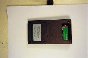
Click to zoom
Application Details
- Equipment Class
- DXX - Part 15 Low Power Communication Device Transmitter
- Date of Grant
- Mar 29, 1999
- Application Purpose
- Original Equipment
- Date of Application
- Feb 09, 1999
- Frequency Range
- 902.00000000 - 928.00000000
- Company
- EquuPulse Co
- Country
- United States
Documents & Files
Document Text
Text extracted from the exhibit documents filed with the FCC. Open a document above to read the original.
Operational Description
APPLICATIONS INCLUDE: nContinuous Data Transfer nHome/Industrial Automation nWireless Networking nRemote Control nRemote Access nRemote Monitoring/Telemetry nFire/Security Alarms n Long-Range RFID n High-Quality Wireless Audio n Analog Signal Transfer n General Wire Elimination Page 1 HPSERIES TRANSMITTER MODULE DESIGNGUIDE FEATURES: n 8 Binary Selectable Transmission Frequencies n High Output Power (+5dBm typical into a 50 ohm load) n C o s t - E ff e c t i v e n Precision Synthesized Frequency Reference n Direct Analog/Serial Interface n High Data Rate (50Kbps max.) n Can Be Used To Transmit Analog (Including Audio) or Digital Data n Wide Supply Range (2.7-16V DC) n Power-Down & CTS Functions n No Production Tuning nNo External RF Components Required (Except A n t e n n a ) n Manufacturing-Friendly SIP-Style Packaging DESCRIPTION: The HP series transmitter module is designed for the c o s t - e f fe c t i ve, high-perfo rmance wireless tra n s fer of analog or digital data, in the popular 902-928MHz band. The transmitter offers eight selectable channels and, when paired with an HP series receiver, is capable of transmitting analog and digital information for distances up to 1/4 mile. To assure robust performance under all field conditions the transmitter employs an adva n c e d microprocessor-controlled synthesized architecture.L i ke all Linx modules, the HP series requires no tuning and in most cases no ex t e rnal RF components ( except an antenna), making integration stra i g h t fo r ward even fo r engineers lacking previous RF ex p e ri e n c e. Figure 1:Physical Dimensions HIGHPERFORMANCE RFMODULE TXM-900-HP PART# DESCRIPTION M D E V- 9 0 0 - H PE valuation Kit 900 MHz T X M - 9 0 0 - H PTransmitter 900 MHz R X M - 9 0 0 - H PR e c e i ver 900 MHz O R D E R I N GI N F O R M AT I O N Figure 3:Maximum ratings table Figure 2:Performance data table PERFORMANCEDATA TXM-900-HP Page 2 A B O U TT H E S EM E A S U R E M E N T S The performance parameters listed below are based on module operation at 25°C from a 5VDC supply unless otherwise noted. Absolute Maximum Ratings: Supply voltage Vcc, using pin 7-0.3to+18 VDC Operating temperature0°Cto+70°C Storage temperature-45°Cto+85°C Soldering temperature+260°C for 10 sec. Any input or output pin-0.3toVcc *NOTE* Exceeding any of the limits of this section may lead to permanent damage of the device.Furthermore, extended operation at these maximum ratings may reduce the life of this device. ParameterDesignationMin.TypicalMax.UnitsNotes Input Voltage (Vcc)V CC 2.7–16.0VDC– Supply currentI CC 141517mA– Sleep currentI CS ––50μA Operating frequencyF C 902–928MHz– Overall frequency accuracy-50–+50KHz– Output Power+2+5+7dBm– Spurious Emissions––-50dBc1 Harmonic Emissions––-43dBc– Occupied Bandwidth–32–KHz– PONto CTS High TimeT PON– 715mSec– Minimum OffT MINOFF 1––mSec– Channel Change TimeTime––1.2mSec– Fdev758095KHz p-p– * C AU T I O N * This product incorp o rates numerous static-sensitive components. A l ways wear an ESD wrist strap and observe proper ESD handling procedures when wo rking with this dev i c e. Failure to observe this precaution may result in module damage or fa i l u r e. 1.Tested to 2nd Harmonic Notes: Page 3 Figure 8:Modulation Linearity for Triangle Wave Input Figure 9:Output Power vs. Supply Voltage Figure 4:Power-On Timing TYPICALPERFORMANCEGRAPHS Figure 6:Modulation Linearity for Square Wave Input Figure 7:Modulation Linearity for Sine Wave Input Figure 5:Channel Change Timing PHYSICALPACKAGING The transmitter is packaged as a hybrid through- hole SIP-style module with 10 pins spaced at .1" i n t e rvals with a .3" gap between pins 2 & 3. Baseband components occupy the rear of the board while high-frequency components are grouped on the front. PRODUCTION CONSIDERATIONS The SIP module may be installed using hand- or wave-solder techniques.The module should not be subjected to reflow.If the module is subject to production wash cycles, adequate drying time should be allowed prior to power-up.If the wash cycle introduces contaminants, the module’s perfo rmance may be adversely affected. Figure 10:Physical package 1.00 V/div1.00 V/div +/-1.0 V 10.0 ms/div 0.0 s 120 mV 2.00 V/div1.00 V/div+/-1.0 V 500 μs/div 0.0 s1.67 V Page 4 PINDESCRIPTION Figure 11:Pin functions and equivalent circuits Page 5 THEORY OF OPERATION The HP-TXM is a high-performance, eight-channel, FM transmitter capable of transmitting analog or digital data. Digital information is modulated at the transmitter using FSK (frequency shift keying), the binary fo rm of frequency modulation. FSK offers significant advantages over AM-based modulation methods, i.e., increased noise immunity and the ability of the receiver to “capture”in the presence of multiple signals. These advantages will be particularly appreciated in crowded bands like those in which the HP operates.While FSK modulation is not the most bandwidth-efficient manner of modulating digital data, it is an excellent choice for reliable, low-cost, low-power RF products such as the HP series. To transmit analog information the module reverts to FMmodulation.In this mode simple to complex waveforms can be introduced at the transmitter’s data pin and recovered with minimal distortion at the receiver’s analog output pin. The user-supplied antenna is connected at pin 2 (see Figure 1).The HP series transmitters are designed to operate with a 50-ohm load. An accurate 12.00MHz VCXO (voltage-controlled crystal oscillator) serves as the frequency reference for the transmitter.The modulation input pin is connected to the VCXO through a 25kHz two-pole low-pass filter.The low-pass filter is used to shape the incoming data and limit the transmission bandwidth to 25kHz. The reference frequency is directly modulated.This method affords two benefits. First, it eliminates the need for a frequency conversion in the transmitter, reducing size, cost, and current consumption.Second, it allows the modulation to occur within the loop …
Text truncated - open the document above for the full version.
RF Exposure Info
February 10, 1999 Federal Communications Commission Equipment Authorization Division 7435 Oakland Mills Road Columbia, MD 21046 Subject: Maximum Permissible Exposure calculations for FCC ID: OEE700 To whom it may concern, Serena Medial is submitting a low power transmitter for an equine heart monitor device. The unit operates in the 902 to 928 MHz band with a radiated output power of .025 mW. The monitor transmits on one frequency that is user selectable. Assuming a worst case of no duty cycle. For an Isotropic radiator the surface area of a sphere can be used to determine the area over which the transmitter energy is radiated. Surface area of a sphere = 4*Π*radius 2 The exposure level can be calculated as follows : MPE distance = (output power*duty cycle*10(antenna gain/10)/(4*Π*Exposure Limit (mW/cm 2 ) 1/2 OEE700 MPE distance = (.025 mW*1*/4*3.14*1) 1/2 = .045 cm = .017 in If you have any questions please do not hesitate to call me. Sincerely, Chris Byleckie Technical Director Electronic Compliance Laboratories
Test Report
A804006.DOC1 CFR Title 47 PartsCFR Title 47 Parts 15.249 Certification15.249 Certification FCC ID: OEE700FCC ID: OEE700 EMI TEST REPORTEMI TEST REPORT onon Model 700Model 700 Prepared ForPrepared For Serena Medical Electronics Co., Inc.Serena Medical Electronics Co., Inc. P.O Box 20785P.O Box 20785 San Jose, CA 95610San Jose, CA 95610 TEL: (408) 745-7438TEL: (408) 745-7438 FAX: (408) 745-7438FAX: (408) 745-7438 Prepared byPrepared by Electronic Compliance Laboratories, Inc.Electronic Compliance Laboratories, Inc. Test Report Number: A901008Test Report Number: A901008 Date of Test: February 5, 1999Date of Test: February 5, 1999 If this document is reproduced, it must be reproducedIf this document is reproduced, it must be reproduced in its entirety.in its entirety. A901008.DOC 2 Table of Contents 1.0 Certification of Compliance .........................................................................3 2.0 General Information ......................................................................................4 3.0 Test Facility....................................................................................................5 4.0 Test equipment..............................................................................................5 5.0 Data Reporting Format..................................................................................6 6.0 Detector Functions........................................................................................6 7.0 Frequency Range of Investigation................................................................6 8.0 FCC Class Types...........................................................................................7 9.0 FCC Limits......................................................................................................8 10.0 Test Methods................................................................................................9 11.0 Labeling Requirements...............................................................................11 12.0 Summary of Measurements........................................................................12 APPENDIX A Restricted Band Data....................................................................14 APPENDIX B Radiated Emissions.......................................................................23 APPENDIX C Set-up Photos................................................................................26 A901008.DOC 3 1.0 Certification of Compliance Description:Model 700 Transmitter Serial Number: Prototype Applicant: Serena Medical Electronics Co., Inc. Type of Test: FCC-15, Class A ( Certification) part 15.249 Date of Test: February 5, 1999 Tested By:Suresh Kondapalli The above equipment was tested by Electronic Compliance Laboratories, Inc. and found to be in compliance with the requirements set forth in the FCC Rules and Regulations, Part 15, Subpart C (15.203, 15.205, 15.209, 15.249). The equipment, in the configuration described in this report, shows that the maximum emission levels emanating from this equipment are within the compliance requirements. ____________________________________ Chris ByleckieDate Technical Director A901008.DOC 4 2.0 General Information Applicant:Serena Medical Electronics Co., Inc. P.O Box 20785 San Jose, CA 95160 Contact Person: Jim McIntosh Equipment Under Test: Model 700 Serial Number: Prototype FCC ID#:OEE700 Report Number: A901008 Date of Test: February 5, 1999 Manufacturer: Serena Medical Electronics Co., Inc Type of Test:FCC part 15, Subpart C, (15.203, 15.205, 15.209, 15.247), Class A Digital Device. Frequency Range:30 MHz to 1000 MHz - Radiated Emissions, Class A 902 MHz to 928 MHz - part 15.249 Up to the 10th harmonic of the fundamental (9270 MHz) part 15.35(a) Summary Pass/Fail: Passed 15.209 Radiated Emissions: The Model 700 meet all the requirements for Part 15.209 Class A limit. See Appendix B for Data Sheet and plots. 15.249 Operation within the 902 - 928 MHz band: The Model 700 met all the requirements for 15.249. See data in Appendix A. A901008.DOC 5 3.0 Test Facility Name:Electronic Compliance Laboratories Location:1249 Birchwood Drive Sunnyvale, CA 94089 Site Filing:A site description is on file at the Federal Communications Commission P.O. Box 429 Columbia, MD 21045 Types of Sites:Open Field Radiated and Indoor (Screen Room). Line Conducted: All sites are constructed and calibrated to meet ANSI C63.4-1994 requirements. Test facility is recognized by the National Voluntary Laboratory Accreditation Program for satisfactory compliance with criteria established in Title 15, Part 285 Code of Federal Regulations. NVLAP Code:20089 effective through: March 31, 1999 4.0Test Equipment The following list contains equipment used at EC Laboratories, Inc. for compliance testing. The equipment conforms to the American National Standard Specifications for Electromagnetic Interference and Field Strength Instrumentation from 10 kHz to 1000 MHz. DescriptionManufacturerS/NModel No.Cal. Due Date EMI ReceiverHP3325A001378456A5/3/99 Pre-ampHP313A068298447F5/10/99 Pre-ampHP3008A005278449B4/5/99 LISNEM2532ANS-25/26/12/99 Spectrum AnalyzerHP3137A011838563A5/22/99 PlotterHP2644V003657470AN/A Power MeterHP2342A07307435B4/4/99 Power SensorHPN/A8482A4/12/99 Biconical AntennaEM677EM-69123/3/99 Log-Periodic AntennaEM858EM-69504/18/99 Horn AntennaEM6231RGA-606/6/98 1.2 - 4GHz FilterFSY001HM1160-11SS3/25/99 4 - 10 GHz FilterFSY001HM2950-15SS3/25/99 10 - 18 GHz FilterFSY001HP8601-7SS3/25/99 HP = Hewlett Packard EM = Electro Metrics The antenna used at the time the data was taken is indicated on each data page. The antenna height and polarization are also noted on the data pages. The calibration of the measuring instruments, including any accessories that may effect such calibration, are checked frequently to assure their accuracy. Adjustments are made and correction factors applied in accordance with instructions contained in the manual for the measuring instrument. A…
Text truncated - open the document above for the full version.
Test Report
CONREVSMA001 CONREVSMA006 CONREVSMA002 CONREVSMA003.031 for .031 BoardThickness CONREVSMA003.062 for .062 BoardThickness RPSMA Connector Line PCB Mount Versions 575 SE Ashley PlacePHONE:541-471-6256 Grants Pass,OR 97526FAX:541-471-6251 Page 1 of 2 HORIZONTAL PCB EDGE MOUNT RIGHT ANGLE PCB MOUNT VERTICAL PCB MOUNT MULTI-MOUNT HORIZONTAL PCB Mounting Options www.linxtechnologies.com CONREVSMA004 CONREVSMA005 CONREVSMA007 RPSMA Connectors Cable End Versions Page 2 of 2 CABLE END - FEMALE - FOR RG-174FRONT MOUNT BULKHEAD RECEPTACLE CABLE END - MALE FOR RG-174 CONREVSMA005-C08.5 (8.5" STANDARD) CONREVSMA005-CXX.XX (XX.XX=CUSTOM LENGTH,1K MIN.ORDER) PRE-ASSEMBLED MALE BULKHEAD-WITH RG-174 575 SE Ashley PlacePHONE:541-471-6256 Grants Pass,OR 97526FAX:541-471-6251 www.linxtechnologies.com
Test Report
EFFICIENCY CONSIDERATIONS At first it might appear that equal effort should be devoted to optimizing the performance of both the transmitter and receiver antennas.Yet this is not alwaystrue.In many modular and discrete designs the transmitter’s output power is purposefully set higher than the legal limit.This allows a designer to utilize an inefficient antenna to achieve size, cost, or cosmetic objectives and still radiate the maximum allowed output power.With a high-performance whip it is often necessary to attenuate the output so concerns over efficien- cy at the transmitter are not as great as at the receiver.Once a transmitter is radiating full legal power the receiver and its antenna are the determining factor in range performance.If you are striving to achieve maximum range, careful attention to the receiver’s antenna is critical. Typical VSWR Graphs PW/CW Series RH Series GROUND-PLANE REQUIREMENT Since a 1/4-wave antenna is not inherently self-resonant it must radiate against a ground-plane in order to operate effectively.The ground-plane acts as a counterpoise that forms the other quarter-wave element, in essence forming an effective half-wave dipole.The ground-plane can be a metal case or ground-fill areas on a circuit board.All Linx antennas are characterized using a 4.5”X 4.5”ground-plane centered and oriented at a 90° angle as shown below.Such an orientation is often not practical due to size and configuration constraints.In these instances a designer must make the best use of the area available to create as much ground-plane in proximity to the base of the antenna as possible.In instances where the antenna is remotely located or the antenna is not in close proximity to a circuit board plane or grounded metal case, a small metal plate may be fabricated to maximize antenna performance. The antenna is a significant and often overlooked component that can have a substantial impact on the performance and integrity of an RF link.When correctly utilized in keeping with the following instructions,Linx quarter-wave antennas provide exceptional performance in a compact and rugged physical package. CONNECTION CONSIDERATIONS PW-Style antennas are coax-fed whips designed for perm a n e n t product mounting.The threaded bushing is normally insert e d through a hole in a user’s case and then anchored using a 1/4"-28tpi nut.If required, a piece of metal may also be anchored by the nut to serve as a ground-plane as described below.In some applications a user may prefer to use a Pem ® -style fastener which can be preinstalled in the case. CWand RHantennas have an integral reverse polarity S M Aconnector (RP-SMA). This style of connector is utilized to comply with FCC c e rtification requirements which call for a unique connector not widely ava i l a bl e to the general public.RP- S M Aconnectors are not widely advertised in order to insure continued compliancy but they are available in a variety of styles from many sources including Amphenol, Z e u s, and EF Johnson. As connectors from these companies tend to be quite expensive you may wish to consider those offered by Linx and pictured below.Linx RP-SMA’s provide equal or superior quality and are significantly lower in cost. Mounting of PW-Style Whip RP-SMA’s are suitable for use with any CW or RH series antenna and meet FCC Part 15 or comparable certification requirements. Linx RP-SMA Connector Family CONREVSMA002CONREVSMA003CONREVSMA001 CONREVSMA004CONREVSMA005 USING LINX 1/4-WAVE WHIP ANTENNAS LINX TECHNOLOGIES, INC. 575 S.E. ASHLEYP L A C E GRANTS PASS, OR 97526 Phone: (541) 471-6256 FAX: (541) 471-6251 h t t p : / / w w w. l i n x t e c h n o l o g i e s . c o m U.S. CORPORATE HEADQUARTERS: Linx Technologies is continually striving to improve the quality and function of its products;for this reason, we reserve the right to make changes without notice.The information contained in this Data Sheet is believed to be accurate as of the time of publication.Specifications are based on representative lot samples.Values may vary from lot to lot and are not guaranteed.Linx Technologies makes no guarantee, warranty, or representation regarding the suitability of any product for use in a specific application.None of these devices is intended for use in applica- tions of a critical nature where the safety of life or property is at risk.The user assumes full lia- bility for the use of product in such applications.Under no conditions will Linx Technologies be responsible for losses arising from the use or failure of the device in any application, other than the repair, replacement, or refund limited to the original product purchase price.Some devices described in this publication are patented.Under no circumstances shall any user be conveyed any license or right to the use or ownership of these patents. Disclaimer © 1998 by Linx Technologies, Inc. The stylized Linx logo, Linx, and “Wireless made Simple” are the trademarks of Linx Technologies, Inc. Printed in U.S.A. Microstrip formulas (Er= Dielectric constant of PCB material) Effective DielectricWidth/HeightDielectricCharacteristic Constant(W/d)ConstantImpedance 4.81.83.5950.0 423.0751.0 2.5532.1248.0 ANTENNA FEED-LINE The connection between an RF module and the antenna can be a significant source of loss or detuning.As the frequency of operation increases, overall antenna length is reduced.Thus, even a short antenna feed-line can have a significant effect on the operational bandwidth of the antenna.In general, if a trace length in excess of .200 is required to reach the antenna connector, a coax or a microstrip PCB transmission line should be used to prevent loss and minimize antenna detuning. LEGAL ISSUES In many countries including the United States there are considera ble restri c t i o n s placed on antennas used with unlicensed products.Most notable are connection requirements which generally call for an antenna to be either permanently attached or to utilize a unique and proprietary connector.…
Text truncated - open the document above for the full version.
Contact Information
Applicant
James A. McIntosh(President)
Technical Contact
electronic compliance laboratorieschris byleckie
[email protected]408-747-1490
Non-Technical Contact
electronic compliance laboratorieschris byleckie
[email protected]408-747-1490
Test Firm
Electronic Compliance LaboratoriesChip Matheny
[email protected]408-747-1490
Technical Specifications
| # | Rule Parts | Frequency Range | Power Output |
|---|---|---|---|
| 1 | 15C | 902 MHz - 928 MHz | 25.00 mW |