OF3MPC30Cellular base station repeater
RF CELLutions, LLC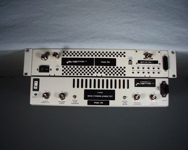
Click to zoom
Application Details
- Equipment Class
- TNB - Licensed Non-Broadcast Station Transmitter
- Date of Grant
- Aug 18, 1999
- Application Purpose
- Original Equipment
- Date of Application
- Feb 24, 1999
- Equipment Note
- Cellular base station repeater
- Frequency Range
- 869.00000000 - 894.00000000
- Company
- RF CELLutions, LLC
- Country
- United States
Documents & Files
Document Text
Text extracted from the exhibit documents filed with the FCC. Open a document above to read the original.
Users Manual
COMMUNICATION CERTIFICATION LABORATORYTEST REPORT: 73-6760 FCC ID: OF3MPC30 Page 50 of 59 Exhibit 7 Back view of the test set-up
Users Manual
COMMUNICATION CERTIFICATION LABORATORYTEST REPORT: 73-6853 FCC ID: OF3MPC30 Page 55 of 70 Exhibit 8 Exhibit 8: User’s Manual The MPC 30 is comprised of two previously certified units that are purchased from AML Communications and Celwave which are repackaged as the RF CELLutions, LLC Model MPC 30. The MPC 30 consists of a AML Multicarrier Linear Amplifier, previously certified under the following FCC ID number: (LX7PA0870), and a Celwave Bi-Directional Amplifier (BDA), previously certified under the following FCC ID number: IWDBDA48551-N. RF CELLutions, LLC does not produce a user’s manual, they use the AML Communications and Celwave manuals. Enclosed as a separate pdf file are copies of the AML Communications and Celwave manuals for both the BDA and Multicarrier Linear Amplifier.
Cover Letter(s)
COMMUNICATION CERTIFICATION LABORATORYTEST REPORT: 73-6760 FCC ID: OF3MPC30 Page 58 of 59 Exhibit 13 Exhibit 13: Cover Letters March 10, 1999 FEDERAL COMMUNICATIONS COMMISSION Equipment Authorization Division 7435 Oakland Mills Road Columbia, MD 21046 To Whom It May Concern: Enclosed is a FCC Part 22, Certification application for the RF CELLutions, LLC Model MPC 30, FCC ID: OEWMPC30. Please let me know if I can be of further assistance. Sincerely yours, COMMUNICATION CERTIFICATION LABORATORY Joseph W. Jackson V.P. Marketing COMMUNICATION CERTIFICATION LABORATORYTEST REPORT: 73-6760 FCC ID: OF3MPC30 Page 59 of 59 Exhibit 13 Request for Confidentiality
External Photos
COMMUNICATION CERTIFICATION LABORATORYTEST REPORT: 73-6760 FCC ID: OF3MPC30 Page 4 of 59 Exhibit 3 Exhibit 3: Photographs of Overall Appearance Front View of the MPC 30 COMMUNICATION CERTIFICATION LABORATORYTEST REPORT: 73-6760 FCC ID: OF3MPC30 Page 5 of 59 Exhibit 3 Back View of the MPC 30 COMMUNICATION CERTIFICATION LABORATORYTEST REPORT: 73-6760 FCC ID: OF3MPC30 Page 6 of 59 Exhibit 3 Right Side View of the MPC 30 COMMUNICATION CERTIFICATION LABORATORYTEST REPORT: 73-6760 FCC ID: OF3MPC30 Page 7 of 59 Exhibit 3 Left Side View of the MPC 30
ID Label/Location Info
COMMUNICATION CERTIFICATION LABORATORYTEST REPORT: 73-6760 FCC ID: OF3MPC30 Page 1 of 59 Exhibit 1 Exhibit 1: FCC ID Label In accordance with the requirements of Sections 2.925 and 2.926 of the FCC Rules, the following information will be permanently affixed to the RF CELLutions, LLC Model MPC 30 as shown in the sketch below. Due to the size of the equipment, the label contains only the FCC ID only, and the compliance statement is provided in the User’s manual. COMMUNICATION CERTIFICATION LABORATORYTEST REPORT: 73-6760 FCC ID: OF3MPC30 Page 2 of 59 Exhibit 1 Photograph showing the label placement
ID Label/Location Info
COMMUNICATION CERTIFICATION LABORATORYTEST REPORT: 73-6760 FCC ID: OF3MPC30 Page 1 of 59 Exhibit 1 Exhibit 1: FCC ID Label In accordance with the requirements of Sections 2.925 and 2.926 of the FCC Rules, the following information will be permanently affixed to the RF CELLutions, LLC Model MPC 30 as shown in the sketch below. Due to the size of the equipment, the label contains only the FCC ID only, and the compliance statement is provided in the User’s manual. COMMUNICATION CERTIFICATION LABORATORYTEST REPORT: 73-6760 FCC ID: OF3MPC30 Page 2 of 59 Exhibit 1 Photograph showing the label placement
Internal Photos
COMMUNICATION CERTIFICATION LABORATORYTEST REPORT: 73-6760 FCC ID: OF3MPC30 Page 52 of 59 Exhibit 9 Exhibit 9: Internal Photographs The MPC 30 is comprised of two previously certified units that are purchased from AML Communications and repackaged as the RF CELLutions, LLC Model MPC 30. The MPC 30 consists of a AML Bi-Directional Amplifier (BDA) and a Multicarrier Linear Amplifier, previously certified under the following FCC ID numbers: BDA (LX7BD09002) and Multicarrier Linear Amplifier (LX7PA0870). RF CELLutions, LLC does not make any internal changes to either unit; therefore, the internal photographs are the same as filed with the above mention FCC ID numbers. Enclosed below are the inside view of the BDA and Multicarrier Linear Amplifier. Inside view of BDA COMMUNICATION CERTIFICATION LABORATORYTEST REPORT: 73-6760 FCC ID: OF3MPC30 Page 53 of 59 Exhibit 9 Inside view of Multicarrier Linear Amplifier
Internal Photos
COMMUNICATION CERTIFICATION LABORATORYTEST REPORT: 73-6853 FCC ID: OF3MPC30 Page 56 of 70 Exhibit 9 Exhibit 9: Internal Photographs The MPC 30 is comprised of previously certified units that are purchased from AML Communications and Celwave. These units are then repackaged as the RF CELLutions, LLC Model MPC 30. The MPC 30 consists of a Celwave Bi-Directional Amplifier (BDA) and an AML Multicarrier Linear Amplifier, previously certified under the following FCC ID numbers: The BDA model 48551-N is manufactured by Celwave and was certified under FCC ID: IWDBDA48551-N The Multicarrier Linear Amplifier is manufactured by AMP and was certified under FCC ID: LX7PA0870. Inside view of Amplifier COMMUNICATION CERTIFICATION LABORATORYTEST REPORT: 73-6853 FCC ID: OF3MPC30 Page 57 of 70 Exhibit 9 Inside view of the BDA COMMUNICATION CERTIFICATION LABORATORYTEST REPORT: 73-6853 FCC ID: OF3MPC30 Page 58 of 70 Exhibit 9 Inside view of the BDA TX Input Filter RX Output Filter COMMUNICATION CERTIFICATION LABORATORYTEST REPORT: 73-6853 FCC ID: OF3MPC30 Page 59 of 70 Exhibit 9 Inside view of the BDA RX AGC Amplifier COMMUNICATION CERTIFICATION LABORATORYTEST REPORT: 73-6853 FCC ID: OF3MPC30 Page 60 of 70 Exhibit 9 Inside view of the BDA RX Pre Amplifier COMMUNICATION CERTIFICATION LABORATORYTEST REPORT: 73-6853 FCC ID: OF3MPC30 Page 61 of 70 Exhibit 9 Inside view of the BDA TX AGC Amplifier TX Pre Amplifier COMMUNICATION CERTIFICATION LABORATORYTEST REPORT: 73-6853 FCC ID: OF3MPC30 Page 62 of 70 Exhibit 9 Inside view of the BDA TX Output Filter RX Input Filter COMMUNICATION CERTIFICATION LABORATORYTEST REPORT: 73-6853 FCC ID: OF3MPC30 Page 63 of 70 Exhibit 9 Inside view of the BDA RX Power Amplifier COMMUNICATION CERTIFICATION LABORATORYTEST REPORT: 73-6853 FCC ID: OF3MPC30 Page 64 of 70 Exhibit 9 Inside view of the BDA TX Power Amplifier
RF Exposure Info
COMMUNICATION CERTIFICATION LABORATORYTEST REPORT: 73-6760 FCC ID: OF3MPC30 Page 56 of 59 Exhibit 11 Exhibit 11: RF Exposure/Environmental Evaluation The MPC 30 is professionally installed and always greater than 2.5 cm from the user; therefore, testing for RF exposure is not required.
Test Report
COMMUNICATION CERTIFICATION LABORATORYTEST REPORT: 73-6760 FCC ID: OF3MPC30 Page 10 of 59 Exhibit 6 Exhibit 6: Test Report TEST REPORT FROM: COMMUNICATION CERTIFICATION LABORATORY 1940 W. Alexander Street Salt Lake City, UT 84119-2039 U.S.A. Tel: (801) 972-6146 Fax: (801) 972-8432 TEST OF: MPC 30 To Part 2 Subpart J and Part 22 Subpart H of the FCC Rules and Regulations Test Report Serial No: 73-6760 APPLICATION FOR TYPE ACCEPTANCE: Cellular Re-Radiator Base Station Transceiver Applicant: RF CELLutions, LLC 6851 Hwy 73 Evergreen, CO 80439 Issue Date: March 10, 1999 Dates of Test: February 24 -26, 1999 COMMUNICATION CERTIFICATION LABORATORYTEST REPORT: 73-6760 FCC ID: OF3MPC30 Page 11 of 59 Exhibit 6 CERTIFICATION OF ENGINEERING REPORT This report has been prepared by Communication Certification Laboratory to verify compliance of the device described below with the requirements to Part 2 Subpart J and Part 22 Subpart H of the FCC Rules and Regulations. This report may be reproduced in full, partial reproduction may only be made with the written consent of the laboratory. The results in this report apply only to the sample tested. -Applicant:RF CELLutions, LLC -Manufacturer:RF CELLutions, LLC -Model Number:MPC 30 -FCC ID:OF3MPC30 -Brand Name:MPC On this 10 th day of March 1999, I, individually, and for Communication Certification Laboratory, certify that the statements made in this engineering report are true, complete, and correct to the best of my knowledge, and are made in good faith. COMMUNICATION CERTIFICATION LABORATORY Checked by: William S. Hurst, P.E. Vice President Tested by: Roger J. Midgley EMC Engineering Manager COMMUNICATION CERTIFICATION LABORATORYTEST REPORT: 73-6760 FCC ID: OF3MPC30 Page 12 of 59 Exhibit 6 SECTION 1. Measurement Requirements 1.1 Introduction The following data is submitted for Certification of a cellular re-radiator for RF CELLutions, LLC, in accordance with Part 2, Subpart J and Part 22, Subpart H of FCC Rules and Regulations. See technical description in Exhibit 10. 1.2 Measurements Required for Certification '' 2.1033 (c)(14) Measurement Data The measurement data that is required by ' 2.1046 through ' 2.1057 is included in Section 2 of this report. The data was measured in accordance with the procedures set out in ' 2.1041. '' 2.1046 '' 22.913 RF Power Output A mobile station transmitter must be capable of reducing power in steps of 4 dB on command from a land station. Each power level must be maintained within the range of +2 dB and -4 dB of its nominal level. Due to wide frequency range, which the re-radiator may operate, measurements were performed on a channel near the bottom, on a channel near the middle and on a channel near the top of the spectrum. Result: The results of the RF output power testing are shown in section 2.1 and the test procedures are described in Appendix 1. '' 2.1047 '' 22.915 Modulation Characteristics The MPC 30 does not provide a voice modulation, it only retransmits the received signal; therefore, the requirements of this section do not apply. COMMUNICATION CERTIFICATION LABORATORYTEST REPORT: 73-6760 FCC ID: OF3MPC30 Page 13 of 59 Exhibit 6 '' 2.1049 Occupied Bandwidth The occupied bandwidth, that is the frequency bandwidth such that, below its lower and above its upper frequency limits, the mean powers radiated are each equal to 0.5 percent of the total mean power radiated by a given emission shall be measured under the following conditions as applicable: (c) Radiotelephone transmitters equipped with a device to limit modulation or peak envelope power shall be modulated as follows. For single sideband and independent sideband transmitters, the input level of the modulation signal shall be 10 dB greater than that necessary to produce rated peak envelope power. (1) Other than sideband or independent sideband transmitters – when modulated by a 2500 Hz tone at an input level 16 dB greater than that necessary to produce 50 percent modulation. The input level shall be established at the frequency of maximum response of the audio modulation circuit. Result: The results of the occupied bandwidth testing are shown in Section 2.2 and the test procedures are described in Appendix 1. '' 2.1051 '' 22.917 (d) '' 22.917 (e) Spurious Emissions at Antenna Terminals ' 22.917 (d) For F1D emissions, the mean power of emission must be attenuated below the mean power of the unmodulated carrier (p) as follows: (1) On any frequency removed from the carrier frequency by more than 20 kHz but not more than 45 kHz: at least 26 dB. (2) On any frequency removed from the carrier frequency by more than 45 kHz but not more than 90 kHz: at least 45 dB. (3) On any frequency removed from the carrier frequency by more than 90 kHz, up to the first multiple of the carrier frequency: at least 60 dB or 43+10log P dB, whichever is the lesser attenuation. ' 22.917 (e) Out of band emission The mean power of emission must be attenuated below the mean power of the unmodulated carrier (P) on any frequency twice or more than twice the fundamental frequency by: at least 43+10log P dB. COMMUNICATION CERTIFICATION LABORATORYTEST REPORT: 73-6760 FCC ID: OF3MPC30 Page 14 of 59 Exhibit 6 Due to the relatively wide range over which the output power can be varied, measurements were conducted at three different power levels (1 carrier or 30 watts, 4 carriers or 7.5 watts, and 16 carriers or 1.9 watts) Result: The frequency range from 30 MHz to the tenth multiple of the carrier frequency was investigated to measure any antenna- conducted emissions. Shown in Tables 1 through 3 (Section 2.3) are the emission levels from 30 MHz to 90 kHz below the carrier frequency and from 90 kHz above the carrier frequency to the tenth multiple of the carrier frequency. Shown in Plots 1 through 3 is the emissions/occupied bandwidth from 90 kHz below the carrier frequency to 90 kHz above the carrier frequency. These plots show the MPC 30 tuned to the lower channel, the results with the MPC 30 tune…
Text truncated - open the document above for the full version.
Test Report
COMMUNICATION CERTIFICATION LABORATORYTEST REPORT: 73-6853 FCC ID: OF3MPC30 Page 13 of 70 Exhibit 6 Exhibit 6: Test Report TEST REPORT FROM: COMMUNICATION CERTIFICATION LABORATORY 1940 W. Alexander Street Salt Lake City, UT 84119-2039 U.S.A. Tel: (801) 972-6146 Fax: (801) 972-8432 TEST OF: MPC 30 To Part 2 Subpart J and Part 22 Subpart H of the FCC Rules and Regulations Test Report Serial No: 73-6853 APPLICATION FOR TYPE ACCEPTANCE: Cellular Re-Radiator Base Station Transceiver Applicant: RF CELLutions, LLC 6851 Hwy 73 Evergreen, CO 80439 Issue Date: July 7, 1999 Dates of Test: June 2 - 30, 1999 COMMUNICATION CERTIFICATION LABORATORYTEST REPORT: 73-6853 FCC ID: OF3MPC30 Page 14 of 70 Exhibit 6 CERTIFICATION OF ENGINEERING REPORT This report has been prepared by Communication Certification Laboratory to verify compliance of the device described below with the requirements to Part 2 Subpart J and Part 22 Subpart H of the FCC Rules and Regulations. This report may be reproduced in full, partial reproduction may only be made with the written consent of the laboratory. The results in this report apply only to the sample tested. -Applicant:RF CELLutions, LLC -Manufacturer:RF CELLutions, LLC -Model Number:MPC 30 -FCC ID:OF3MPC30 -Brand Name:MPC On this 7 th day of July 1999, I, individually, and for Communication Certification Laboratory, certify that the statements made in this engineering report are true, complete, and correct to the best of my knowledge, and are made in good faith. COMMUNICATION CERTIFICATION LABORATORY Checked by: William S. Hurst, P.E. Vice President Tested by: Roger J. Midgley EMC Engineering Manager COMMUNICATION CERTIFICATION LABORATORYTEST REPORT: 73-6853 FCC ID: OF3MPC30 Page 15 of 70 Exhibit 6 SECTION 1. Measurement Requirements 1.1 Introduction The following data is submitted for Certification of a cellular re-radiator for RF CELLutions, LLC, in accordance with Part 2, Subpart J and Part 22, Subpart H of FCC Rules and Regulations. See technical description in Exhibit 10. 1.2 Measurements Required for Certification '' 2.1033 (c)(14) Measurement Data The measurement data that is required by ' 2.1046 through ' 2.1057 is included in Section 2 of this report. The data was measured in accordance with the procedures set out in ' 2.1041. '' 2.1046 '' 22.913 RF Power Output A mobile station transmitter must be capable of reducing power in steps of 4 dB on command from a land station. Each power level must be maintained within the range of +2 dB and -4 dB of its nominal level. Due to wide frequency range, which the re-radiator may operate, measurements were performed on a channel near the bottom, on a channel near the middle and on a channel near the top of the spectrum. Result: The results of the RF output power testing are shown in section 2.1 and the test procedures are described in Appendix 1. '' 2.1047 '' 22.915 Modulation Characteristics The MPC 30 does not provide a voice modulation, it only retransmits the received signal; therefore, the requirements of this section do not apply. COMMUNICATION CERTIFICATION LABORATORYTEST REPORT: 73-6853 FCC ID: OF3MPC30 Page 16 of 70 Exhibit 6 '' 2.1049 Occupied Bandwidth The occupied bandwidth, that is the frequency bandwidth such that, below its lower and above its upper frequency limits, the mean powers radiated are each equal to 0.5 percent of the total mean power radiated by a given emission shall be measured under the following conditions as applicable: (c) Radiotelephone transmitters equipped with a device to limit modulation or peak envelope power shall be modulated as follows. For single sideband and independent sideband transmitters, the input level of the modulation signal shall be 10 dB greater than that necessary to produce rated peak envelope power. (1) Other than sideband or independent sideband transmitters – when modulated by a 2500 Hz tone at an input level 16 dB greater than that necessary to produce 50 percent modulation. The input level shall be established at the frequency of maximum response of the audio modulation circuit. Result: The results of the occupied bandwidth testing are shown in Section 2.2 and the test procedures are described in Appendix 1. '' 2.1051 '' 22.917 (d) '' 22.917 (e) Spurious Emissions at Antenna Terminals ' 22.917 (d) For F1D emissions, the mean power of emission must be attenuated below the mean power of the unmodulated carrier (p) as follows: (1) On any frequency removed from the carrier frequency by more than 20 kHz but not more than 45 kHz: at least 26 dB. (2) On any frequency removed from the carrier frequency by more than 45 kHz but not more than 90 kHz: at least 45 dB. (3) On any frequency removed from the carrier frequency by more than 90 kHz, up to the first multiple of the carrier frequency: at least 60 dB or 43+10log P dB, whichever is the lesser attenuation. ' 22.917 (e) Out of band emission The mean power of emission must be attenuated below the mean power of the unmodulated carrier (P) on any frequency twice or more than twice the fundamental frequency by: at least 43+10log P dB. COMMUNICATION CERTIFICATION LABORATORYTEST REPORT: 73-6853 FCC ID: OF3MPC30 Page 17 of 70 Exhibit 6 Due to the relatively wide range over which the output power can be varied, measurements were conducted at three different power levels (1 carrier or 30 watts, 4 carriers or 7.5 watts, and 16 carriers or 1.9 watts) Result: The frequency range from 30 MHz to the tenth multiple of the carrier frequency was investigated to measure any antenna- conducted emissions. Shown in Tables 1 through 3 (Section 2.3) are the emission levels from 30 MHz to 90 kHz below the carrier frequency and from 90 kHz above the carrier frequency to the tenth multiple of the carrier frequency. Shown in Plots 1 through 3 is the emissions/occupied bandwidth from 90 kHz below the carrier frequency to 90 kHz above the carrier frequency. These plots show the MPC 30 tuned to the lower channel, the results with the MPC 30 tuned to the…
Text truncated - open the document above for the full version.
Test Report
COMMUNICATION CERTIFICATION LABORATORYTEST REPORT: 73-6853 FCC ID: OF3MPC30 Page 39 of 70 Exhibit 6 Table 4 (3 Carriers / Intermodulation Test) The emissions must be attenuated 43 + 10 log P dB where P = Mean power of the unmodulated carrier. The maximum power of the modulated carrier was measured to 0.407 W (26.1 dBm) See plot on page 41, therefore, the emissions must be attenuated 43 + 10 log (0.407) = 39.1 dB. The criteria is 26.1 dBm – 39.1 dB = -13.0 dBm. Transmitting at 880.0, 881.5 and 889.0 MHz Frequency Range MHz Frequency MHz Corrected Level dBm Criteria dBm 30 - 20032.9-41.3-13.0 200 – 1000395.7-37.5-13.0 1000 - 15001011.5-43.0-13.0 1500 - 20001772.0-20.1-13.0 2000 - 30002642.0-30.3-13.0 3000 - 40003540.9-44.3-13.0 4000 - 50004447.0-41.6-13.0 5000 - 60005280.0-50.6 *-13.0 6000 - 70006160.0-43.8 *-13.0 7000 - 75007040.0-42.7 *-13.0 7500 - 80007920.0-42.7 *-13.0 8000 - 90008800.0-42.7 *-13.0 * Noise Floor RBW = 30 kHz VBW = 100 kHz COMMUNICATION CERTIFICATION LABORATORYTEST REPORT: 73-6853 FCC ID: OF3MPC30 Page 41 of 70 Exhibit 6 Plot Intermodulation test (Output from MPC30) dBm 30 20 10 0 -10 -20 -30 -40 -50 -60 -70 SoftPlot Measurement Presentation Trace A Centre: 880.000000 MHzSpan: 100.000000 MHz Res BW: 30 kHzVid BW: 100 kHzSweep: 300 ms 7/6/99 9:44:23 AMHP8566B Intermodulation Test - Limit Line 1 MHz below and above transmit band (889MHz and 891 MHz) Trace A3 CDMA Signals (2 near low end of band and 1 near high end of band) PASS 1 1 889.400000 MHz 26.1000 dBm
Test Setup Photos
COMMUNICATION CERTIFICATION LABORATORYTEST REPORT: 73-6760 FCC ID: OF3MPC30 Page 49 of 59 Exhibit 7 Exhibit 7: Test Set-Up Photograph Front view of the test set-up COMMUNICATION CERTIFICATION LABORATORYTEST REPORT: 73-6760 FCC ID: OF3MPC30 Page 50 of 59 Exhibit 7 Back view of the test set-up
Test Setup Photos
COMMUNICATION CERTIFICATION LABORATORYTEST REPORT: 73-6853 FCC ID: OF3MPC30 Page 53 of 70 Exhibit 7 Exhibit 7: Test Set-Up Photograph Front view of the test set-up COMMUNICATION CERTIFICATION LABORATORYTEST REPORT: 73-6853 FCC ID: OF3MPC30 Page 54 of 70 Exhibit 7 Back view of the test set-up
Contact Information
Applicant
Shane Evans(President)
Technical Contact
Communication Certification LaboratoryRoger J Midgley
[email protected](801) 972-6146
1940 W. Alexander Street · Salt Lake City, Utah · United States
Test Firm
Communication Certification Lab.Scott Earl
Technical Specifications
| # | Rule Parts | Frequency Range | Power Output | Emission | Tolerance |
|---|---|---|---|---|---|
| 5 | 22.901(d) | 869 MHz - 894 MHz | 30 W | DXW | 2.5 ppm |