OFXCRFLINK000
Orion Research, Inc.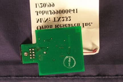
Click to zoom
Application Details
- Equipment Class
- DXX - Part 15 Low Power Communication Device Transmitter
- Date of Grant
- Jun 09, 1999
- Application Purpose
- Original Equipment
- Date of Application
- Feb 25, 1999
- Frequency Range
- 916.00000000 - 916.00000000
- Company
- Orion Research, Inc.
- Country
- United States
Documents & Files
Document Text
Text extracted from the exhibit documents filed with the FCC. Open a document above to read the original.
Users Manual
ORION rf link Instruction Sheet PLEASE READ BEFORE OPERATING INTRODUCTION The Orion rf link transmission device allows information to be sent from your Orion instrument to a printer or personal computer for datalogging purposes, without the use of printer cables. rf link has a maximum transmission range of approximately 25 feet, but may be minimized depending on the number of objects surrounding the area. For optimal results keep both the Transmit module and Receive module free and clear of solid, metal objects to reduce the likelihood of signal impedance. WHAT’S INSIDE? When opening up the product for the first time the following items should be included: .QryDESCRIPTION 1Transmit module 1Receive module 2Cables (Transmit & Receive) 1Software Disk (DataCOLLECT) 19 DB Computer Adapter 2Adhesive Strips 1Instruction Sheet Please check to make sure the previous listed items are present. If any items are missing call Orion Customer Service at 800-225-1480 I. OPERATING INSTRUCTIONS Connecting Transmit Module to Instrument: <Diagram of Transmit module, a transmit cable & a meter> Compatible Orion Products: .(&~&, 940, 920A, 862A, 850, 810, 720A, 710A, 620, 550A, 525A, 520A, 420A, 370, 350, 330, 290A, 250A, 162A, 150, 145, 125 and 115) 1. Take the transmit cable and insert end (lA) into the input located on the rf link module. 2. Connect to instrument by inserting opposite end (1 B) to the R5232 port of the instrument. NOTE: Make sure that the instrument is turned off before connecting the if link Transmit module. Connecting Receive Module to Printer/Computer: <Diagram of Receive module, cable & PRT300 printer> 1. Take the Receive cable and insert end (2A) into the input located on the rf link module. 2. Connect to printer by inserting opposite end (2B) into the printer port. NOTE: When connecting the if link Receive module to a printer, it is important to ensure that the printer is turned OFF. Connecting when the printer is on could cause erratic printer operation. <Diagram of cable connected to RFLink module, adapter & computer> 3. To connect the rflink Receive module to the PC, plug the DB25-FIDB9-F adapter (3) into the cable end (2B) before inputting into computer port. II. LOADING SOFTWARE To install DataCOLLECT software onto your PC complete the following steps: Windows 3.1 1. Insert disk into drive 2. From File Manager select RUN in the File menu 3. In the command line type “A:\setup”, selecting appropriate drive. 4. Click OK Windows 95 & NT 1. Insert disk into drive 1. Click on _______ Run 2. Select 3. In command line type “A:\setup”, selecting appropriate drive. 4. Click OK III. TROUBLESHOOTING If the rf link units are not responding to the print function, make sure to check that all cables are properly and securely connected to the appropriate ports. IV. NOTICE OF COMPLIANCE V. WARRANTY Drop in Text from 1999 Product Catalog VI. ORDERING INFORMATION Order NumberDescription RELINKif link Data Transmission Device INCLUDES: Transmit module & cable, Receive module & cable, PC adapter, DataCOLLECT software, adhesive strips Accessories Order NumberDescription RELKOlTransmitter Cable RFLKQ2Receiver Cable RFLKO3PC Adapter RFLKO4DataCOLLECT Software VII SPECIFICATIONS
Test Report
Intertek Testing Services NA Inc. 70 Codman Hill Road Boxborough, MA 01719 Telephone (978) 263-2662 Fax (978) 263-7086 Orion Research Inc. Emissions Testing Performed on the RF Link Data Transfer Transmitter Model: TX232 FCC Part 15, Subpart C, Section '15.249 Date of Test: January 19 and January 20, 1999 JOB #J99000641A VFV/Rbt ORI0641A.VFV January 26, 1999 DOT: January 19 and January 20, 1999 Contact: Mr. Joe Cheng Total No. of Pages Contained in this Report: All services undertaken are subject to the following general policy: Reports are submitted for exclusive use of the client to whom they are addressed. Their significance is subject to the adequacy and representative character of the samples and to the comprehensiveness of the tests, examinations or surveys made. No quotations from reports or use of Intertek Testing Services name is permitted except as expressly authorized by Intertek Testing Services in writing. This report must not be used to claim product endorsement by NVLAP, NIST or any agency of the U.S. government. INTERTEK TESTING SERVICES NA INC. TO:Orion Research Inc. Mr. Joe Cheng FROM:Vathana F. Ven DATE:January 20, 1999 JOB #:J99000641A RE:Emissions Testing Performed On The RF Link Data Transfer Transmitter, Model: TX232 On January 19 and January 20, 1999 we tested the TX232 to determine if it was in compliance with the FCC Part 15, Subpart C, Section '15.249. A production version of the sample was received on January 19, 1999 in good condition. We found that the unit met the requirements when tested as received. The fundamental output power and harmonic emission limits are outlined in paragraph (a) of this section. The fundamental field strength allowed at a distance of 3 meters was 50,000 μV/m. Harmonic emission at frequencies outside of the forbidden bands of the FCC Part 15, Subpart C '15.205 must be lower than the limit of 500 μV/m. Spurious Scan (30-1000 MHz) Digital Circuit Portion Radiated emissions showed the system to be 3.7 dB below the FCC Part 15, Subpart C, Section '15.209 emissions at 191.7 MHz. All other emissions were at least 3.8 dB below the applicable limits AC mains line-conducted emissions testing was not performed as the unit is battery powered. INTERTEK TESTING SERVICES NA INC. TO:Orion Research Inc. Mr. Joe Cheng FROM:Vathana F. Ven DATE:January 20, 1999 JOB #:J99000641A RE:Emissions Testing Performed On The RF Link Data Transfer Transmitter, Model: TX232 Fundamental Scan (916.5 MHz) Transmitter Circuit Portion The maximum level of the fundamental signal at 916.5 MHz was 31, 623 μV/m, which is 4 dB below the FCC Part 15, Subpart C, Section '15.249 requirement. Spurious and Harmonic Scan (916.5-9165 MHz) Radiated emissions limits showed the system to be 6 dB below the FCC Part 15, Subpart C, Section '15.249 and '15.209 emission requirement at 3666.0 MHz. All other emissions were at least 7 dB below the applicable limits. Summary In summary, this report confirms that the TX232 is compliant with the FCC Part 15, Subpart C, Section '15.249 requirements when production units conform with the initial sample. Please address all questions and comments concerning this report to Andrew J. Bellezza, Staff Engineer/Emissions . INTERTEK TESTING SERVICES Laboratory Measurements, Intentional RadiatorsJob Number: J99000641A Rev. September 1, 1992 (PT15C.IR) 1 LABORATORY MEASUREMENTS Pursuant To Part 15, Subpart C For Intentional Radiators Manufacturer (Name and Address):Orion Research Inc. 500 Cummings Center Beverly, MA 01915 Attention:Mr. Joe Cheng Model Number:TX232 Serial Number:Not Labelled Site:1C Certification We attest to the accuracy of this report: SignatureSignature Vathana F. Ven Testing Performed ByReviewer TitleTitle/Date INTERTEK TESTING SERVICES Laboratory Measurements, Intentional RadiatorsJob Number: J99000641A Rev. September 1, 1992 (PT15C.IR) Introduction The following is a description of the test procedure used by Intertek Testing Services in the measurements of transmitters operating under Part 15, Subpart C, General Requirements. A.Test Set-Up: The test set-up and procedures described below are designed to meet the requirements of ANSI C63.4 (1992). 1.The test site is plastic and fiber glass with a groundplane. The site has attenuation characteristics which meet the requirements of ANSI C63.4 (1992). Information on the site has been filed with the FCC as required by Rule '2.948. The address of the site is 70 Codman Hill Road, Boxborough, Massachusetts. 2.Power to the site is nominal line voltage of 117 V AC and 230 V AC , 60 Hz. 3.The equipment under test (EUT) is placed on a wooden turntable which is four feet in diameter and approximately one meter in height above the groundplane. During the radiated emissions test, the turntable is rotated and any cables leaving the EUT are manipulated to find the configuration resulting in maximum emissions. The antenna height and polarization are also varied during the search for maximum signal levels. The height of the antenna is varied from one meter to four meters. 4.Detector function for radiated emissions is in peak or quasi-peak mode. Average readings, were taken at frequencies above 1 GHz. INTERTEK TESTING SERVICES Laboratory Measurements, Intentional RadiatorsJob Number: J99000641A Rev. September 1, 1992 (PT15C.IR) A.Test Set Up (cont'd) 5.Antenna used below 1000 MHz was EMCO, Inc. For measurements between 1000 MHz and 18000 MHz, where required, an Emco Double-Ridge Guide Horn Antenna was used. Alternately, for measurements above 1 GHz, an EMCO M/N 3115 Horn Antenna may have been used. 6.The field strength measuring equipment used included: Spectrum Analyzer:Hewlett Packard 8593A Preamplifiers:MITEQNSP4000-NF, CDI P-950 LISN:Solar Electronics Additional equipment or comments: Equipment is calibrated at frequent intervals. INTERTEK TESTING SERVICES Laboratory Measurements, Intentional RadiatorsJob Number: J99000641A Rev. September 1, 1992 (PT15C.IR) A.Test Set Up (cont'd) 7.The frequency rang…
Text truncated - open the document above for the full version.
Test Report
Intertek Testing Services Boxborough, MA COMPANY: Orion Research TABLE: 1MODEL: TX232 Date of Test: 01/19.1999 NOTES: Radiated Emissions Field Field Distance Antenna Pre-An~ Averaging Pulse Strength Strength Limits Frequency Reading Factor Factor Gain Factor Desensitization 3 m ~ 3 m ~ 3 m Margin (MHz) (dBuV) (dB) (dB) (dB) (dB) (dB) (dBuVfm) (uV/m) (uVfm) (dB) 916.000 77 0 29 16 0 0 90 31623 50000 -4 1832.900 33 0 31 22 0 0 42 122 500 -123666.000 33 0 38 22 0 0 48 260 500 -64582.500 27 0 39 22 0 0 44 155 500 -105499.000 27 0 42 22 0 0 47 221 500 -7 No other harmonic or spurious emissions were detected at a test distance of 0.3 meter. Test Engineer: Vathana yen program: txl5 v3.1 pagej/~ of___ Intertek Testing Services Radiated Emissions I Interference Table: 2 Company: ORIONTested by: Vathana Ven Model: TX232 Location: Site 1 Job No.: J99000641 Detector: HP 8591 E Date: 01/1 9199 Antenna: EMCO BICON 1224 Standard: FCC 15 PreAmp: PREl CDI-1648 Class: BGroup: None Cable(s): none none Notes: Initial scan forspurious emissions Distance:3 Signature: An t. Pal . (v h) Freque ncy (MHZ) Readin g (dBuV) Antenn a Factor (dB) Cable Loss (dB) Pre- amp Factor (dB) Distanc e Factor (dB) Net dBuV/m Limit dBuV/mMargi n ~ -9.6 V54.0336.99.40.015.90.030.440.0 V80.0038.37.10.016.10.029.340.0 - 10.7 V121.7536.17.40.016.30.027.243.5-16.3 V143.8033.58.20.016.30.025.343.5 - 18.2 H184.4043.39.90.016.40.036.843.5-6.7 H191.7046.010.20.016.40.039.843.5-3.7 H202.8045.610.50.016.40.039.743.5 - 3.8 H206.5044.810.70.016.40.039.143.5-4.4 H223.6042.011.50.016.40.037.146.0-8.9 H278.4030.012.90.016.40.026.546.0 - 19.5 Intertek Testing Services NA Inc. 70 Codman Hill Road, Boxborough, MA 01719 Telephone (978) 263-2662 Fax (978) 263-7086
Contact Information
Applicant
John E Meserve(QA Manager)
Technical Contact
Intertek Testing Services NA Inc.Andrew J Bellezza
[email protected]978-263-2662
70 Codman Hill Road · Boxborough, Massachusetts · United States
Non-Technical Contact
Intertek Testing Services NA Inc.Jody K Zarnowiec
[email protected]978-263-2662
Test Firm
Intertek Testing Services NA Inc.Diana Montvitt
508-263-2662
Technical Specifications
| # | Rule Parts | Frequency Range | Power Output |
|---|---|---|---|
| 1 | 15C | 916 MHz - 916 MHz | - |