OHSAETM-1Tire Pressure Monitoring System
Automotive Safety Devices, Inc.
Click to zoom
Application Details
- Equipment Class
- DXX - Part 15 Low Power Communication Device Transmitter
- Date of Grant
- May 06, 1999
- Application Purpose
- Original Equipment
- Date of Application
- Mar 21, 1999
- Equipment Note
- Tire Pressure Monitoring System
- Frequency Range
- 433.00000000 - 433.00000000
- Country
- United States
Documents & Files





Document Text
Text extracted from the exhibit documents filed with the FCC. Open a document above to read the original.
Users Manual
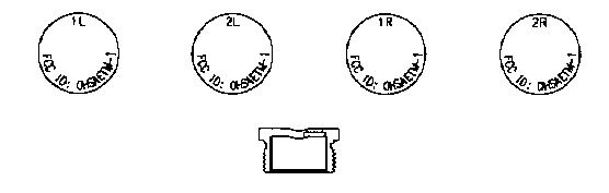
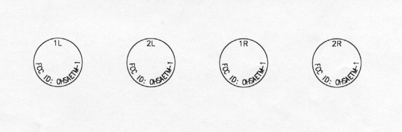
USER MANUAL TIRE PRESSURE MONITORING SYSTEM Page 1 of 3 Model AETM-1 The Monitor. The Vehicle Tire Pressure Monitoring System (VTPMS) consists of state-of-the-art, battery-powered components, which are called The Monitor and The Sensor. Together, these intelligent devices monitor air pressure in the tires of a vehicle and alert the driver in the event that pressure in any tire falls under an user- programmed pressure level. A typical four-tire VTPMS consists of a monitor that is placed in a convenient location where it is visible to the driver and four small pressure sensors. Each sensor is securely fastened to the tire’s valve stem. To minimize power consumption, the sensor operates in a dormant mode and it is only powered when the tire is in motion. The sensor’s internal clock regularly awakens the sensor to read the air pressure in the tire and relays the Data to the Monitor via a Pulse Modulated radio frequency (RF) signal. Upon receiving the RF message, The Monitor compares the tire pressure value received to a user-programmed value. If the values match, the monitor alerts the driver by flashing the “Low” tire pressure value and by activating a buzzer. The VTPMS is capable of reading current tire pressure on any tire location. FIG. 1 Monitor Display Module Features • System STATUS\Low-pressure warning light and buzzer. (STATUS) • Tire sensor position identification • Low sensor battery light (BAT LOW) • Mode button (>) Alarm Condition: In the Monitoring Mode and while the vehicle is in motion, the Monitor flashes the System Status RED indicator and activates the buzzer for 8 seconds immediately after it has received a “Low Tire Pressure” message from a tire-installed sensor. The Alarm condition requires immediate driver attention. If the Low tire condition continues, the monitor will again alert the driver at two-minute intervals until the faulty tire has been repaired or replaced. The driver can silence the Buzzer by pressing the pushbutton switch labeled “>”. The Monitor expects to receive at least one message from each sensor every 5 minutes. If the sensor fails to transmit within the time limit, the Monitor will report the sensor as missing or faulty by blinking the tire location LED. STATUS BAT LOW > USER MANUAL TIRE PRESSURE MONITORING SYSTEM Page 2 of 3 Model AETM-1 Monitor Installation. 1. Install Monitor at a convenient place in the vehicle where it is visible to the driver. Secure the Monitor in place. (Velcro is recommended). 2. Connect one end of supplied power cord to the Cigarette Lighter receptacle, and the other end to the miniature receptacle situated on the left-hand side of the monitor. 3. If powered correctly, the Monitor will light up the Status GREEN indicator, and it will start to listen for messages transmitted by tire pressure sensors. Programming the monitor. Programming the monitor entails storing the tire pressure value (psi) that the monitor will use to sound the buzzer, and to warn the driver of a Low Tire Pressure condition in the vehicle. The monitor needs to be powered down to begin this procedure. 1. While pressing the push button switch labeled “>”, connect the cigarette lighter adapter plug to the receptacle located on the back of the monitor. This action puts the monitor in the “Low Pressure Alarm Trigger Programming Mode”. If this operation is successful, the monitor will light up all tire sensor location indicators. 2. Push the “>” pushbutton switch repeatedly and as necessary until the display shows the desired Low- Pressure Alarm Trigger value. 3. Push the “>” pushbutton switch for three seconds to complete the programming operation and to enable the monitor to start listening for messages from tire pressure sensor(s). The Sensor. All sensor are factory-programmed, and when installed, they provide a steady pressure status of the tires. Sensor Installation. 1. Secure sensors in tire valve stems at tire locations indicated by the label on sensor caps. Make sure sensor is securely screwed in to the valve stem to avoid air leaks. Refer to Fig. 2. a. Installed sensor labeled 1L on the Front Left Tire b. Installed sensor labeled 2L on the Rear Left Tire c. Installed sensor labeled 1R on the Front Right Tire d. Installed sensor labeled 2R on the Rear Right Tire FIG. 2. IR 1L 2R 2L USER MANUAL TIRE PRESSURE MONITORING SYSTEM Page 3 of 3 Model AETM-1 FCC Compliance Statement This device complies with Part 15 of the FCC Rules. Operation is subject to the following two conditions: (1) This device may not cause harmful interference and (2) this device must accept any interference received, including interference that may cause undesired operation. FCC Notice This device has been tested and found to comply with the limits for a Class B digital device, pursuant to Part 15 of the FCC Rules. These limits are designed to provide reasonable protection against harmful interference in a residential installation. This device generates, uses and can radiate radio frequency energy and, if installed and used in accordance with the instruction, may cause harmful interference to radio communications. However, there is no guarantee that interference will not occur in a particular installation. If this device does cause harmful interference to radio or television reception, the user is encouraged to try to correct the interference by one or more of the following measures: • Reorient or relocate the receiving antenna. • Increase the separation between the computer and receiver. • Connect the computer into an outlet on a circuit different from that to which the receiver is connected. • Consult the dealer or an experienced radio\TV technician for help. Caution: Any changes or modifications not expressly approved by the grantee of this device could void the user authority to operate the equipment.
Operational Description
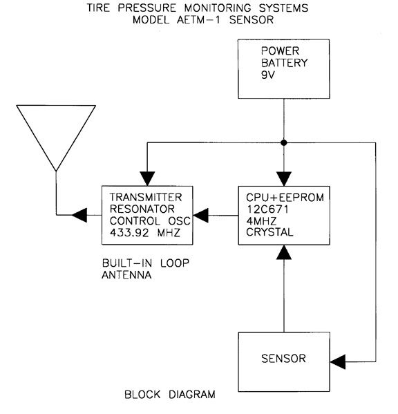
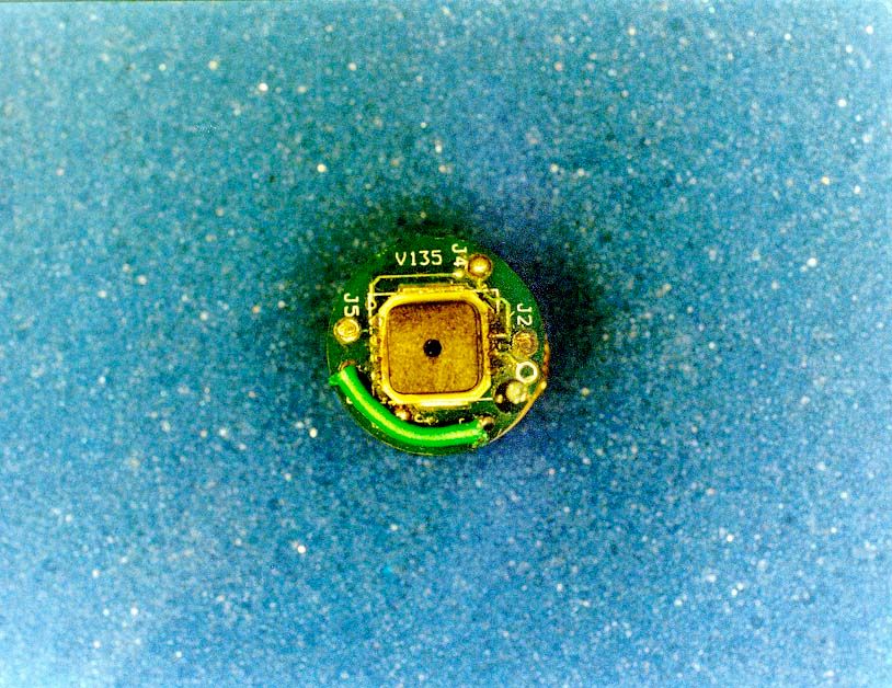
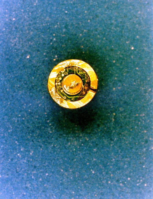
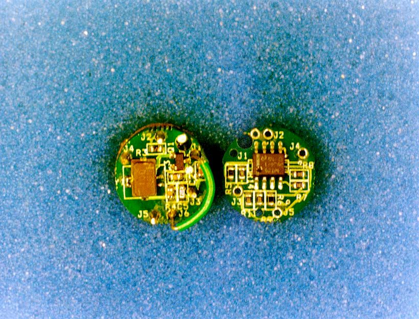
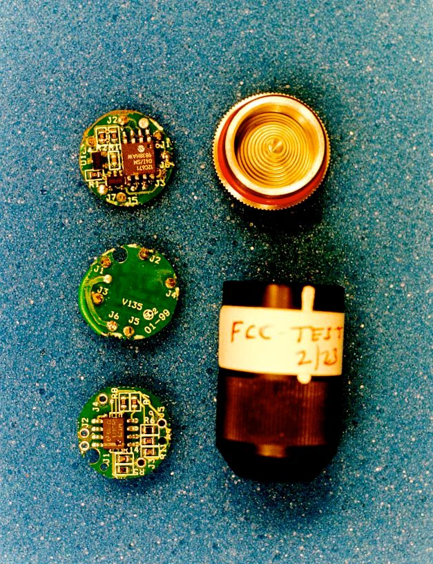
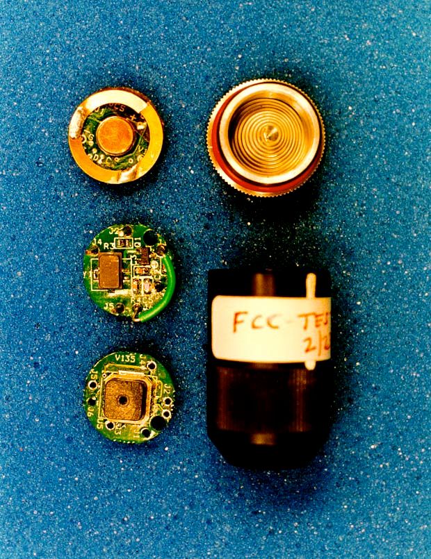
Tire Pressure Monitoring System Model AETM-1 Sensor Description of circuitry in device The sensor operates on 9v Battery stack that is constructed with 3 individual lithium battery together. The sensor module has three boards: Sensor/Amplifier, Transmitter and CPU. The Sensor/amplifier board performs two functions: 1. Generates voltage according to pressure in the tire. 2. Amplifies the signal as required. CPU board receives the sensor data and converts the analog data to digital format. This formatted data is then sent to transmitter board, which transmits out at 433.92MHz + or -75KHz. The transmitter is designed with a SAW resonator 433.92 MHz oscillator and built-in loop antenna. The CPU runs at 4MHz RC clock generated internally.
Test Report
Page 1 of 20 Report No: FC99-015 CERTIFICATION TEST REPORT FOR THE TIRE PRESSURE MONITORING SYSTEM (TRANSMITTER), AETM-1 FCC PART 15 SUBPART C COMPLIANCE DATE OF ISSUE: MARCH 11, 1999 PREPARED FOR: Advantage Enterprises, Inc. 1610 E. Elm Street Harrisonville, MO 64701 P.O. No: 3504 W.O. No: 70536 PREPARED BY: Joyce Walker CKC Laboratories, Inc. 5473A Clouds Rest Mariposa, CA 95338 Dates of test: January 6,15, February 16, 24, March 1, 1999 Report No: FC99-015 DOCUMENTATION CONTROL: _____________________________ Tracy Phillips Documentation Control Supervisor CKC Laboratories, Inc. APPROVED BY: _____________________________ Dennis Ward Director of Laboratories CKC Laboratories, Inc. This report contains a total of 20 pages and may be reproduced in full only. Partial reproduction may only be done with the written consent of CKC Laboratories, Inc. Page 2 of 20 Report No: FC99-015 TABLE OF CONTENTS Administrative Information.............................................................................................3 Summary Of Results........................................................................................................4 Equipment Under Test (EUT) Description......................................................................4 Measurement Uncertainty................................................................................................4 EUT Operating Frequency...............................................................................................4 Peripheral Devices...........................................................................................................4 Report Of Measurements.................................................................................................5 Table 1: Fundamental Emission Levels...............................................................5 Table 2: Highest Spurious Emission Levels........................................................6 Table A : List Of Test Equipment....................................................................................7 EUT Setup........................................................................................................................8 Test Instrumentation And Analyzer Settings...................................................................8 Table B : Analyzer Bandwidth Settings Per Frequency Range...........................8 Spectrum Analyzer Detector Functions...............................................................9 Peak..........................................................................................................9 Quasi-Peak...............................................................................................9 Average....................................................................................................9 Test Methods....................................................................................................................10 Radiated Emissions Testing.................................................................................10 Occupied Bandwidth............................................................................................11 Sample Calculations.........................................................................................................11 Appendix A : Information About The Equipment Under Test........................................12 I/O Ports...............................................................................................................13 Crystal Oscillators................................................................................................13 Printed Circuit Boards..........................................................................................13 Required EUT Changes To Comply....................................................................13 Cable Information ..............................................................................................................................Er ror! Bookmark not defined. Photograph Showing Radiated Emissions...........................................................14 Photograph Showing Radiated Emissions...........................................................15 Appendix B : Measurement Data Sheets.........................................................................16 Occupied Bandwidth Plot....................................................................................17 Page 3 of 20 Report No: FC99-015 CKC Laboratories, Inc. has Certificates of Accreditation from the following agencies: DATech (Germany); A2LA (USA); FCC (USA); VCCI (Japan); BSMI (Taiwan); HOKLAS (Hong Kong). CKC Laboratories, Inc. has Letters of Acceptance through an MRA for the following agencies: ACA/NATA (Australia); SABS (South Africa); SWEDAC (Sweden); TUV Rheinland-Germany; TUV Rheinland- Korea; TUV Rheinland-Russia; Radio Communication Agency (RA); NEMKO (Norway). ADMINISTRATIVE INFORMATION DATE OF TEST: January 6,15, February 16, 24, March 1, 1999 PURPOSE OF TEST: To demonstrate the compliance of the Tire Pressure Monitoring System, AETM-1, with the requirements for FCC Part 15 Subpart C devices. MANUFACTURER: Automotive Safety Devices, Inc. C/O CM Automotive Systems, Inc. 120 Commerce Way Walnut, CA 91789 REPRESENTATIVE: Phil Zaroor TEST LOCATION: CKC Laboratories, Inc. 110 Olinda Place Brea, CA 92621 TEST PERSONNEL: Skip Doyle & Eddie Wong TEST METHOD: ANSI C63.4 1992 FREQUENCY RANGE TESTED: 30 MHz – 4.4 GHz EQUIPMENT UNDER TEST:Tire Pressure Monitoring System Manuf: CM Automotive Systems, Inc. Model: AETM-1 Serial: NA FCC ID: (pending) Page 4 of 20 Report No: FC99-015 SUMMARY OF RESULTS The Advantage Enterprises, Inc. Tire Pressure Monitoring System, AETM-1, was tested in accordance with ANSI C63.4 1992 for compliance with FCC 15 Subpart C. As received, the above equipment was found to be fully compliant with the limits of FCC 15 Subpart C. The results in this report apply only to the items tested, as iden…
Text truncated - open the document above for the full version.
Contact Information
Applicant
Phillip G Zaroor(President)
909-869-7912Fax: 909-869-7921
Technical Contact
CKC LaboratoriesTracy Phillips
[email protected]1-800-500-4362
5473A Clouds Rest · Mariposa, California · United States
Non-Technical Contact
CKC Laboratories, Inc.Joyce Walker
[email protected]1-800-500-4362
Test Firm
CKC Laboratories, Inc.Steve Behm
Technical Specifications
| # | Rule Parts | Frequency Range | Power Output |
|---|---|---|---|
| 1 | 15C | 433 MHz - 433 MHz | - |