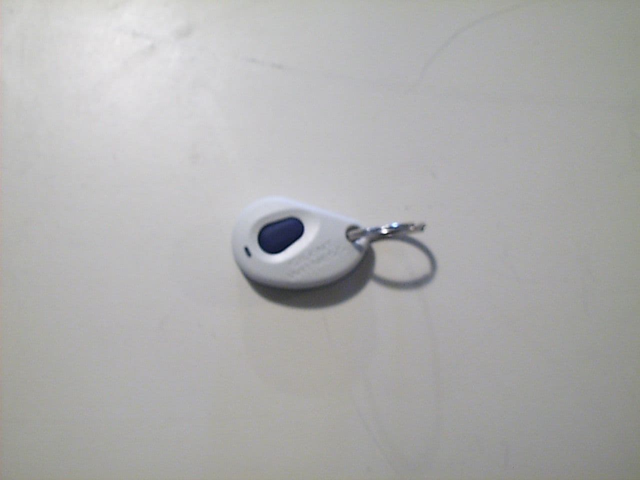
Click to zoom
Application Details
- Equipment Class
- DSC - Part 15 Security/Remote Control Transmitter
- Date of Grant
- Apr 08, 1999
- Application Purpose
- Original Equipment
- Date of Application
- Mar 21, 1999
- Frequency Range
- 433.70000000 - 433.70000000
- Country
- Canada
Documents & Files
Document Text
Text extracted from the exhibit documents filed with the FCC. Open a document above to read the original.
Users Manual
SWC40 Series Surveillance Camera User Guide DOCUMENT 920.0083 REV 1.00 Notices - Warnings Please read the instructions in this guide carefully before you start installing the SWC40 Series Surveillance Camera. Keep this guide for future reference. Safety Warning Any connection of this device to any equipment other than the intended application may result in a safety hazard, and/or defective operation, and/or equipment damage. Disclaimer The information contained in this document is subject to change without notice. Silent Witness Enterprises Ltd., its affiliates, and/or its subsidiaries assume no responsibility for errors and/or omissions contained in this information. Silent Witness Enterprises Ltd. 6554 - 176th Street Surrey, BC V3S 4G5 Canada © 1999 by Silent Witness Enterprises Ltd. 1 Table of Contents Table of Contents..................................................1 Features.................................................................2 Unpacking..............................................................4 Installation.............................................................5 Mounting the Camera...............................................5 Wiring the Camera....................................................8 Aiming the Camera.................................................10 Adjusting Audio Sensitivity......................................12 Recording............................................................14 Recording Modes....................................................14 Using the Handheld Remote Control.......................16 Using the Camera Buttons......................................17 Playback..............................................................19 Playback Setup.......................................................19 Playback Recorded Images....................................20 Programming.......................................................22 Record Menu..........................................................26 Intelligent Light Compensation (ILC) Menu.............28 Motion Menu...........................................................30 Display Menu..........................................................32 Alarm Menu............................................................34 Input Menu..............................................................36 Learning a New Remote Control Code...................38 Routine Maintenance..........................................39 Window Replacement.............................................39 Troubleshooting..................................................40 Warranty and Service.........................................43 Regulatory Notices.............................................44 Specifications......................................................45 Mounting Template.............................................47 2 Features Thank you for purchasing the SWC40 Series Surveillance Camera - the first all-in-one CCTV solution. The SWC40 Series is a high performance camera with digital video recording and video motion detection all within a single compact enclosure that is elegant yet weather resistant and vandal proof. The SWC40 Series features include: qq Reliable, high performance, solid-state cameras qq Digital video recording and playback qq Digital video motion detection qq Intelligent Light Compensation (ILC) qq Programmable features and operating parameters qq Handheld remote arming/disarming control qq A built-in omnidirectional microphone qq A tough, weather resistant, fiberglass reinforced polycarbonate enclosure qq Tamper proof enclosure fasteners qq A universal camera mount for wall or ceiling installations qq Power input transient and reverse polarity protection qq Easy installation and alignment qq Easy maintenance Features - continued 3 Remote control Mounting base Universal mount Microphone Camera enclosure Ceiling mount 4 Unpacking Open the SWC40 packing box and make sure that you have the following items in addition to the User Guide you are now reading: q One Product Warranty Card q One Quick Setup Guide q One SWC40 Series Camera (enclosure and mounting base with factory installed audio/video/power cable) q Two remote control units q Two power adapters q One Quick Change Lens Pack with 2.9, 6.9 and 8.0 mm lenses (3.5 mm pre-installed) q One video playback cable q One video adapter plug q One external input/output signal cable q One SWC40 Installation Kit including: • One security hex key • Four #10×1" Phillips self-tapping screws • Four #10 neoprene washers If you are missing any parts, please contact the dealer you purchased the SWC40 from or call the Silent Witness Service Department (see the Warranty and Service section of this guide on page 43 for telephone numbers). 5 Installation Mounting the Camera The SWC40 Series Camera is designed to be mounted on a wall or ceiling. The SWC40 is weather sealed for indoor or outdoor locations. The wiring can be surface mounted or completely concealed to reduce the risk of tampering. The SWC40 pivot arm is designed to lock in position. Do not try to adjust the pivot arm before loosening the locking screws, as described in the following steps. υ To mount the SWC40 on a wall or ceiling 1 Use the security hex key provided in the SWC40 Installation Kit to loosen the #6-32×2" retaining screw that secures the camera enclosure to the connector block. The retaining screw is held in the camera enclosure and should not be removed. 2 Pull the camera enclosure away from the connector block. Caution: Retaining screw Camera enclosure Connector block Mounting base Installation - continued 6 3 Use the security hex key to remove the four #6-32×1¼" machine screws securing the cover to the mounting base. Position the connector block as shown below and remove the cover. 4 If you do not intend to use the external arming or triggering inputs or the alarm output signals, skip this step. Otherwise, plug the external signal cable connector into the ke…
Text truncated - open the document above for the full version.
ID Label/Location Info
ALLDIMENSIONSAREINMM UNLESSOTHERWISENOTED THECOPYRIGHTOFTHISDOCUMENTISVESTEDINSILENTWITNESS ENTERPRISESLTD.NODISCLOSURE,REPRODUCTION,ORUSEMAYBE MADEEXCEPTBYWRITTENPERMISSIONOFSILENTWITNESS. 6554176Street Surrey,BC CanadaV3S4G5 Tel:(604)574-1526 Fax:(604)574-1527 Ah Size 1 1 1:1 CorelDRAW8 SilentWitnessEnterprisesLtd. www.silent-witness.com FCCID:XXXXXXXXXXXXX Madein China S/N:990126241 P/N:020.0637 B020.0637 A B 99-02-22 99-02-24 DKH DKH FirstRelease RedrawninCorel8,addedFCCID 1.00" R0.047” CharacterType 5ptArialfont CharacterType 5ptArialfont CharacterType 6ptArialfont CharacterType 6ptArialfont E22024 RPR DKH 99-02-03 99-02-22 ARTWORK Label,SerialNumber SWC40RemoteControl Notes: 1.0GENERAL:Artworkforprintingadhesivebackedlabel.SeedocumentE22024formechanicalsizes. 2.0MATERIAL:WhiteVynal 3.0ADHESIVE:
ID Label/Location Info
ALLDIMENSIONSAREINMM UNLESSOTHERWISENOTED THECOPYRIGHTOFTHISDOCUMENTISVESTEDINSILENTWITNESS ENTERPRISESLTD.NODISCLOSURE,REPRODUCTION,ORUSEMAYBE MADEEXCEPTBYWRITTENPERMISSIONOFSILENTWITNESS. 6554176Street Surrey,BC CanadaV3S4G5 Tel:(604)574-1526 Fax:(604)574-1527 Ah Size 1 1 1:1 CorelDRAW8 SilentWitnessEnterprisesLtd. www.silent-witness.com FCCID:XXXXXXXXXXXXX Madein China S/N:990126241 P/N:020.0637 B020.0637 A B 99-02-22 99-02-24 DKH DKH FirstRelease RedrawninCorel8,addedFCCID 1.00" R0.047” CharacterType 5ptArialfont CharacterType 5ptArialfont CharacterType 6ptArialfont CharacterType 6ptArialfont E22024 RPR DKH 99-02-03 99-02-22 ARTWORK Label,SerialNumber SWC40RemoteControl Notes: 1.0GENERAL:Artworkforprintingadhesivebackedlabel.SeedocumentE22024formechanicalsizes. 2.0MATERIAL:WhiteVynal 3.0ADHESIVE:
ID Label/Location Info
ALLDIMENSIONSAREINMM UNLESSOTHERWISENOTED THECOPYRIGHTOFTHISDOCUMENTISVESTEDINSILENTWITNESS ENTERPRISESLTD.NODISCLOSURE,REPRODUCTION,ORUSEMAYBE MADEEXCEPTBYWRITTENPERMISSIONOFSILENTWITNESS. 6554176Street Surrey,BC CanadaV3S4G5 Tel:(604)574-1526 Fax:(604)574-1527 Ah Size 1 1 1:1 CorelDRAW8 SilentWitnessEnterprisesLtd. www.silent-witness.com FCCID:OHWKF40 Madein China S/N:990126241 P/N:020.0637 B020.0637 A B 99-02-22 99-02-24 DKH DKH FirstRelease RedrawninCorel8,addedFCCID 1.00" R0.047” CharacterType 5ptArialfont CharacterType 5ptArialfont CharacterType 6ptArialfont CharacterType 6ptArialfont E22024 RPR DKH 99-02-03 99-02-22 ARTWORK Label,SerialNumber SWC40RemoteControl Notes: 1.0GENERAL:Artworkforprintingadhesivebackedlabel.SeedocumentE22024formechanicalsizes. 2.0MATERIAL:WhiteVynal 3.0ADHESIVE:
Operational Description
1996 Microchip Technology Inc. Preliminary DS21137D-page 1 FEATURES Security • Programmable 28-bit serial number • Programmable 64-bit encryption key • Each transmission is unique • 66-bit transmission code length • 32-bit hopping code • 34-bit fixed code (28-bit serial number, 4-bit button code, 2-bit status) • Encryption keys are read protected Operating • 2.0—6.3V operation • Four button inputs - No additional circuitry required - 15 functions available • Selectable baud rate • Automatic code word completion • Battery low signal transmitted to receiver • Non-volatile synchronization data Other • Easy to use programming interface • On-chip EEPROM • On-chip oscillator and timing components • Button inputs have internal pulldown resistors • Current limiting on LED output • Minimum component count • Synchronous transmission mode Typical Applications The HCS300 is ideal for Remote Keyless Entry (RKE) applications. These applications include: • Automotive RKE systems • Automotive alarm systems • Automotive immobilizers • Gate and garage door openers • Identity tokens • Burglar alarm systems DESCRIPTION The HCS300, from Microchip Technology Inc., is a code hopping encoder designed for secure Remote Keyless Entry (RKE) systems. The HCS300 utilizes the K EE L OQ code hopping technology, which incorporates high secu- rity, a small package outline and low cost, to make this device a perfect solution for unidirectional remote key- less entry systems and access control systems. PACKAGE TYPES HCS300 BLOCK DIAGRAM The HCS300 combines a 32-bit hopping code generated by a non-linear encryption algorithm, with a 28-bit serial number and six status bits to create a 66-bit transmission stream. The length of the transmission eliminates the threat of code scanning and the code hopping mechanism makes each transmission unique, thus rendering code capture and resend (code grabbing) schemes useless. The encryption key, serial number, and configuration data are stored in EEPROM which is not accessible via any external connection. This makes the HCS300 a very secure unit. The HCS300 provides an easy to use serial interface for programming the necessary security keys, system parameters, and configuration data. The encyrption keys and code combinations are pro- grammable but read-protected. The keys can only be verified after an automatic erase and programming operation. This protects against attempts to gain access to keys and manipulate synchronization values. 1 2 3 4 8 7 6 5 S0 S1 S2 S3 V DD LED PWM V SS PDIP, SOIC HCS300 VSS VDD Oscillator Reset circuit LED driver Controller Power latching and switching Button input port 32-bit shift register Encoder EEPROM PWM LED S 3 S 2 S 1 S 0 HCS300 Code Hopping Encoder* KeeLoq is a trademark of Microchip Technology Inc. *Code hopping encoder patents allowed and pending. This document was created with FrameMaker404 HCS300 DS21137D-page 2 Preliminary 1996 Microchip Technology Inc. The HCS300 operates over a wide voltage range of 2.0V to 6.3V and has four button inputs in an 8-pin configuration. This allows the system designer the freedom to utilize up to 15 functions. The only components required for device operation are the but- tons and RF circuitry, allowing a very low system cost. 1.0SYSTEM OVERVIEW K ey Terms • Man ufacturer’s code - a 64-bit word, unique to each manufacturer, used to produce a unique encryption key in each transmitter (encoder). • Encr yption Key - a unique 64-bit key generated and programmed into the encoder during the manufacturing process. The encryption key controls the encryption algorithm and is stored in EEPROM on the encoder device. 1.1Learn The HCS product family facilitates several learn strate- gies to be implemented on the decoder. The following are examples of what can be done. It must be pointed out that their exists some third-party patents on learn- ing strategies and implementation. 1.1.1NORMAL LEARN The receiver uses the same information that is transmit- ted during normal operation to derive the transmitter’s secret key, decrypt the discrimination value and the synchronization counter. 1.1.2SECURE LEARN* The transmitter is activated through a special button combination to transmit a stored 48-bit value (random seed) that can be used for key generation or be part of the key. Transmission of the random seed can be dis- abled after learning is completed. The HCS300 is a code hopping encoder device that is designed specifically for keyless entry systems, primarily for vehicles and home garage door openers. It is meant to be a cost-effective, yet secure solution to such systems. The encoder portion of a keyless entry system is meant to be held by the user and operated to gain access to a vehicle or restricted area. The HCS300 requires very few external components (Figure 2-1). Most keyless entry systems transmit the same code from a transmitter every time a button is pushed. The relative number of code combinations for a low end sys- tem is also a relatively small number. These shortcomings provide the means for a sophisticated thief to create a device that ‘grabs’ a transmission and re-transmits it later or a device that scans all possible combinations until the correct one is found. The HCS300 employs the K EE L OQ code hopping tech- nology and an encryption algorithm to achieve a high level of security. Code hopping is a method by which the code transmitted from the transmitter to the receiver is different every time a button is pushed. This method, coupled with a transmission length of 66 bits, virtually eliminates the use of code ‘grabbing’ or code ‘scanning’. As indicated in the block diagram on page one, the HCS300 has a small EEPROM array which must be loaded with several parameters before use. The most important of these values are: • A 28-bit serial number which is meant to be unique for every encoder • An encryption key that is generated at the time of production • A 16-bit synchronization value The serial number for eac…
Text truncated - open the document above for the full version.
Schematics
4321 3214 DD CC B A B A Code Hopping Encoder Transmitter SheetDrawn by Rev DateNumberProduct Title Description Area Date Rev Silent Witness Enterprises Ltd. PS A Filename E22019.SCH 6554 - 176 Street Surrey, B.C., Canada V3S 4G5 Programming Pads forPOGO Pins 0.100" Centers 1 OF 1 SWC40E22019 98-09-08
Test Report
DATE OF ISSUANCE: 22 MARCH 1999REPORT NUMBER: 990042FCC ID: OHWKF40PAGE 1 OF 18 Partial reproduction of this document is prohibited without prior written consent of Acme Testing. ACME TESTING INC., 2002 VALLEY HWY, P.O. BOX 3, ACME, WASHINGTON 98220-0003 1-888-226-3837. REPORT OF MEASUREMENTS PART 15C - INTENTIONAL RADIATOR DEVICE:TRANSMITTER MODEL:KF40 MANUFACTURER:SILENT WITNESS ENTERPRISES LTD. ADDRESS:6554 176TH STREET SURREY BRITISH COLUMBIA CANADA V3S 4G5 THE DATA CONTAINED IN THIS REPORT WAS COLLECTED ON 11 FEBRUARY 1999 AND COMPILED BY: PAUL G. SLAVENS CHIEF EMC ENGINEER WORK ORDER: 10768-5 DATE OF ISSUANCE: 22 MARCH 1999REPORT NUMBER: 990042FCC ID: OHWKF40PAGE 2 OF 18 1.GENERAL .......................................................................................................................................................................................... 3 1.1P URPOSE....................................................................................................................................................................................... 3 1.2M ANUFACTURER........................................................................................................................................................................... 3 1.3T EST LOCATION............................................................................................................................................................................. 3 1.4T EST PERSONNEL........................................................................................................................................................................... 3 2.TEST RESULTS SUMMARY........................................................................................................................................................... 4 3.DESCRIPTION OF EQUIPMENT AND PERIPHERALS ............................................................................................................ 5 3.1E QUIPMENT UNDER TEST (EUT) ................................................................................................................................................... 5 3.2EUT P ERIPHERALS........................................................................................................................................................................ 5 3.3T HE MODE OF OPERATION DURING TESTING.................................................................................................................................. 5 3.4M ODIFICATIONS REQUIRED FOR COMPLIANCE................................................................................................................................5 4.ANTENNA REQUIREMENT ........................................................................................................................................................... 6 4.1REGULATION................................................................................................................................................................................. 6 4.2R ESULT......................................................................................................................................................................................... 6 5.CONDUCTED EMISSIONS TESTS ................................................................................................................................................ 7 5.1TEST EQUIPMENT.......................................................................................................................................................................... 7 5.2P URPOSE....................................................................................................................................................................................... 7 5.3T EST PROCEDURES........................................................................................................................................................................ 7 5.4T EST RESULTS............................................................................................................................................................................... 7 6.PERIODIC OPERATION ................................................................................................................................................................. 8 6.1REGULATION................................................................................................................................................................................. 8 6.2R ESULT......................................................................................................................................................................................... 8 7.MANUALLY OPERATED TRANSMITTER DEACTIVATION ................................................................................................. 9 7.1REGULATION................................................................................................................................................................................. 9 7.2R ESULT......................................................................................................................................................................................... 9 8.AUTOMATICALLY OPERATED TRANSMITTER DEACTIVATION................................................................................... 10 8.1REGULATION............................................................................................................................................................................... 10 8.2R ESULT....................................................................................................................................................................................... 10 9.PROHIBITION OF PERIODIC TRANSMISSION .....................................................................................................…
Text truncated - open the document above for the full version.
Contact Information
Applicant
David Gordon(Engineering Manager)
Technical Contact
Acme TestingPaul G Slavens
[email protected]360 595-2785
2002 Valley Highway · Acme, Washington · United States
Non-Technical Contact
Acme TestingDesiree R Patterson
[email protected]360 595-2785
Test Firm
Acme Testing Co.Harry Hodes
Technical Specifications
| # | Rule Parts | Frequency Range | Power Output | Emission |
|---|---|---|---|---|
| 1 | 15C | 433.7 MHz - 433.7 MHz | - | A1D |