OHYRFTMTemperature Transmitter
Millennium Enterprises Limited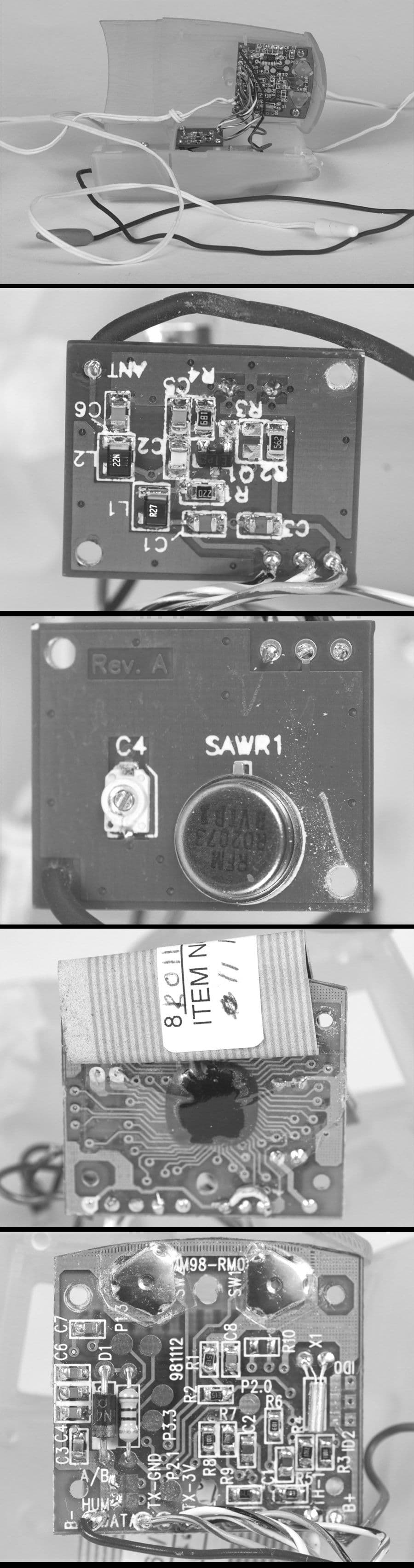
Click to zoom
Application Details
- Equipment Class
- DSC - Part 15 Security/Remote Control Transmitter
- Date of Grant
- Jun 16, 1999
- Application Purpose
- Original Equipment
- Date of Application
- Mar 24, 1999
- Equipment Note
- Temperature Transmitter
- Frequency Range
- 315.00000000 - 315.00000000
- Country
- Hong Kong
Documents & Files
Document Text
Text extracted from the exhibit documents filed with the FCC. Open a document above to read the original.
Users Manual
WeatherSmart ™ Indoor/Outdoor Thermometer Transmitter Photograph of Transmitter WeatherWatch_Tx_manual 2/25/99 2:44 PM Page 1 Contents: Caution ............................................................ About your Transmitter .................................. Transmitter Features ...................................... Transmitter Controls....................................... Getting Started with your Transmitter ......... Setting Up your Transmitter Locating your Transmitter properly Viewing Temperature ..................................... Transmission and Low Battery Indication .... Adding more Transmitters ............................. Problem Solving.............................................. Caution: WeatherWatch_Tx_manual 2/25/99 2:44 PM Page 2 Read this before operating your unit 1. This unit is a sophisticated electronic device. To ensure proper operation and the best possible performance, please read this manual carefully. 2. The unit may be subject to interference from external sources such as transformers, electric motors or other electronic devices. To avoid distortion created by such sources, it is advised that you place the unit as far away as possible from such sources. 3. Under any circumstances, do not open the housing of this unit. To do so may result in damage to the unit. If any foreign object enters the unit, contact customer ser- vice for assistance. 4. Do not apply excessive force when using any of the switches or controls. 5. Do not attempt to clean the unit with a chemical solvent as this might damage the finish. Use a clean, dry cloth. 6. Please be sure to read the “Problem Solving” section of this manual for advice on common operating errors before concluding that your unit is faulty. 7. Always keep this manual in a safe place for future refer- ence. About Your Transmitter: Your WeatherWatch™ Transmitter works with a WeatherWatch™ Thermometer Base Station. The Transmitter measures remote temperature and sends the reading via WeatherWatch_Tx_manual 2/25/99 2:44 PM Page 3 advanced radio technology to your Base Station so you can conveniently keep track of the temperature in a selected remote area. You can use up to 3 Transmitters with each WeatherWatch™ Thermometer Base Station. Please follow this manual for the proper set up, use and care of this revolutionary product. Transmitter Features: Powerful 315 MHZ Digital Signal Transmits a dependable radio signal to your Base Station. ClearCode™ anti-interference technology ensures accurate, distortion-free transmission. 250 Ft. range Transmits remote temperature readings to a Base Station up to 250 feet away. Transmitter works over a wide temperature range This unit operates over a temperature range of -50°F to 158°F. Durable, weatherproof construction. Transmitter displays remote temperature Displays remote temperature in large, easy-to-read numbers, while sending the readings to the Base Station. Transmission Indicator WeatherWatch_Tx_manual 2/25/99 2:44 PM Page 4 Transmission icon on display shows that radio transmission is occurring normally. Low Battery Indicator Indicator icon on display lets you know when batteries needs to be changed. Farenheit or Celcius At the touch of a button, you can select to display the tem- perature reading in Farenheit or Celcius. 3 Position Location Switch Allows you to use up to 3 Transmitters with each Base Station. 2-channel selection avoids interference with other WeatherSmart™ Thermometers in your neighborhood. Extendable Waterproof Temperature Sensor 45” Sensor can be extended from Transmitter’s body to mea- sure the temperature of swimming pools and other hard to reach places. Wall mount Transmitter mounts on a wall with included wall mount. FCC approved FCC part 15 low power device. WeatherWatch_Tx_manual 2/25/99 2:44 PM Page 5 Getting Started With Your Transmitter Setting Up Your Transmitter 1. Select Transmission Channel The first step in setting up your Transmitter involves the selec- tion of a location number. To monitor more than one remote location, you must give each Transmitter its unique location number (1,2, or 3) so that the Base Station can tell them apart. Press the button on the back of the transmitter to select a remote location numbers for each Transmitter. A location number will display on the Transmitter LCD. Continue to press the button to step to each locationavailable. 2. Install batteries Install 2 AA batteries according to the orientation shown in the Battery Compartment. While holding the batteries in place, turn the unit over and check that the Transmitter is dis- playing a temperature. You may need to wait up to a minute for it to read and display the initial temperature. If no temper- ature is displayed after 1 minute, see the “Problem Solving” section of this manual. Use AA lithium batteries for longer battery life and better per- formance in cold temperature conditions 3. Select Fahrenheit and Celcius The temperature shown on the Transmitter display can be in Fahrenheit or Celcius (Fahrenheit is the factory setting). To select either unit of measurement, push the °C/°F button until your preference is shown. WeatherWatch_Tx_manual 2/25/99 2:44 PM Page 6 Your Base Station will display temperature in the unit of mea- surement you select on the Base Station no matter which temperature you select on the Transmitter. 4. Adjust length of Extendible Temperature Sensor Your Transmitter measures temperature at the metal probe end of the 45” Temperature Sensor. The Temperature Sensor can be used fully extended, partially extended or not extend- ed at all. The length is adjusted by storing any excess wire in the Cable Compartment of the Transmitter. When not extend- ed, the probe end conveniently inserts into the lower housing of the Transmitter. Put the probe end of the Temperature Sensor in the lower housing of the Transmitter before bundling the wire into the Cable Compartment. 5. Snap close Battery Compartment Once you have installed the batterie…
Text truncated - open the document above for the full version.
Operational Description
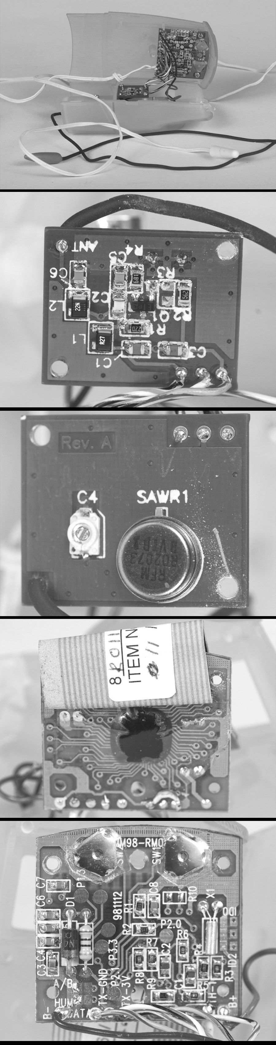
HEADWATERS Research & Development (Canada) Inc. CANADA: 308 Billings Ave., Ottawa, ON K1H 5L3 Tel: (613) 521-6715 Fax: (613) 521-2863 USA: 10 Rogers St., Suite 214, Cambridge MA., 02142. Tel: (617) 621-0337 Fax: (617) 621-0178 REF:RF Thermometer FCC Submission 1) RF Thermometer Overview: The Headwaters RF Thermometer is a portable 3-channel 315 MHz telemetry system for remote indoor / outdoor temperature monitoring over short distances, typically 50 to 250 feet. The product consists of two components. A Temperature and Humidity Receiver that takes received information and shows it on a display. A Temperature and/or Humidity Sensor Transmitter Unit. Up to three transmitter units can be used with a single Receiver. 2) Remote Sensor / TRANSMITTER: The remote sensor / transmitter is the unit consisting of the 315 MHz RF oscillator PCB and the temperature/humidity sensing OKI 64162 microcontroller PCB. The unit transmits 984 millisecond data packets on a schedule of approximately once per minute, with no less than 30 seconds between transmissions. The average duty cycle of any 100 milli-second portion of the transmission does not exceed 28 percent, permitting an increase in the peak output power from the transmitter. The sensor / transmitter is designed to function over a temperature range of -40 C to + 50 C. The measurement accuracy is specified as + / - 1.0 C or better over -40 C to +50 C range with a displayed resolution of 0.1 C. For best performance of transmitter in cold temperatures lithium cells may be used instead of 1.5 Volt alkaline cells. The unit will operate for at least 1 year on two 1.5 Volt AA lithium cells. The RF oscillator is SAW resonator, stabilized, using a one-transistor Colpitts configuration. A wire antenna is connected to the PCB. The oscillator is turned ON by applying +3 volts to the data input ( transistor base ) from a CMOS output pin of the 64162 microcontroller. The microcontroller performs the functions of measuring temperature/humidity, displaying the temperature/humidity on a liquid crystal display, checking battery voltage, sensing the channel ID settings, and sending the data to the transmitter at the appropriate times. The 64162 uses a 32768 Hertz quartz watch crystal for the clock generator. A thermistor is used for temperature sensing. A humidity sensor is used for humidity data. The 984 millisecond transmission consists of a preamble and sync, followed by an 8 bit channel ID, a 3-bit setup word and 2 identical 16-bit temperature/humidity words. Each bit consists of a single 4.576 millisecond RF pulse and 3 x 4.576 milliseconds of no RF(giving a 25% duty cycle for the overall data stream). A Manchester-like encoding technique is used where 1’s and 0’s are defined by the position of the RF pulses. 2a) RF Oscillator PCB: Supply voltage = 3 volts from (2) AA 1.5 volt cells Supply current = approximately 2.3 milliamps, while keyed ON On/off keying (OOK) modulation with 315 MHz carrier. R.F. field strength, accounting for pulsed duty cycle, averaged over a 100 mS window will be a maximum of 78.7 microvolts/metre @ 3 metres ( 11 dB higher than for an unmodulated continuous wave carrier ) as per F.C.C. regulations. Keying rate 54.6 bits/second . Harmonic levels sufficiently low to comply with F.C.C. regulations.. HEADWATERS Research & Development (Canada) Inc. CANADA: 308 Billings Ave., Ottawa, ON K1H 5L3 Tel: (613) 521-6715 Fax: (613) 521-2863 USA: 10 Rogers St., Suite 214, Cambridge MA., 02142. Tel: (617) 621-0337 Fax: (617) 621-0178 2b) Microcontroller PCB: This board uses an OKI 64162 mask-programmed single chip CMOS 4-bit microcontroller, with a supply voltage of 3 volts, a 32768 Hz clock frequency (quartz watch crystal) and a 400khz higher speed RC clock. The typical microcontroller supply current is 15 microamperes. A negative temperature coefficient thermistor is used for temperature sensing. The 64162A TO pin ( transmit out ) goes from ground to + 3 volts to activate the 315 MHz oscillator. Other Details: The battery low detect function ( internal to OKIMSM64162 ) is used to set a flag in the transmission if the batteries become weak . The low battery condition is shown on Transmitter display. The micro-controller initiates data transmissions at intervals (greater than 30 and less than 60 seconds). The connections between the transmitter and the OKIMSM64162 are +3 V, GROUND and DATA. 2c) Transmitter Antenna: This is a 15 inch linear wire with a protective covering. 2d) Transmitter Probe: This is a minimum 45 inch two lead wire with potted thermistor at end. Transmitter User Inputs: Channel Select switch - to select between 3 distinct data ID codes (channels). Degrees C/Degrees F switch – changes the display of temperature information
Parts List/Tune Up Info
RF99 Wireless Thermometer March 12, 1999 Revision: 05 Common TRANSMITTER Component List QuantityPart Description Tx - Mechanical:______________________________________________________________________________ |See Mechanical Transmitter Components List |____________________________________________________________________________________________ Tx - Circuit Boards:___________________________________________________________________________ |1Digital board, double sided FR4, 1.0 mm thick, 0.5 -1.0 ounce copper (36 x 35 mm estimate) |1RF board, double sided FR4, 1.0 mm thick, 1.0 ounce copper (20.2 x 24.6mm) |____________________________________________________________________________________________ Tx - Electro-Mechanical:_______________________________________________________________________ |1LCD glass panel (20 x 33 mm glass size, 14 x 29 mm view area) |1LCD elastomeric connector (32 mm long) |1+1+1Battery contacts for 2 AA cells (+ve, -ve, jumper) |13 wire ribbon cable connecting RF board to digital board |12 wires to connect to battery clips |12 wire connect Humidity sensor (humidity version only) |8+screws for assembly |1Push button momentary switch NormOpen, for C/F change (SW1) |1Push button momentary switch NormOpen, for Channel select (SW2) |____________________________________________________________________________________________ Tx - Digital Board (Production Version) Electrical:_________________________________________________ |1MSM64162, 3V, CMOS micro (capable of humidity circuit installation, not 64162D) (1C1) |132768 Hz quartz watch crystal (X1) |11 K-ohm 1% resistor, SMT or thru hole (R3) |110 K-ohm 1% resistor, SMT or thru hole (R4) |110 K-ohm 5% resistor, SMT (R5) |251 K-ohm 5% resistor, SMT (R1,R2) |60.1 microfarad, minimum 10 volt, ceramic capacitor, SMT (C3, C4, C5, C6, C7, C8) |13300 picofarad NPO or COG ceramic capacitor, SMT (C1) |1HUMIDITY sensor C5-M3 (HM-1) | |1Temp. probe, 1.2 meter x 2wire cable(white & cap, Korean thermistor, Saitek custom potted cap) |(TH-1) (figure RF-Tx-32) | |1IN4001 Diode (D1) |122 ohm 1watt resistor (R11) | |5values tbd HUMIDITY ONLY COMPONENTS (R6, R7, R8, R9, C2) | | |____________________________________________________________________________________________ RF99 Wireless Thermometer March 12, 1999 Revision: 05 RF99 Wireless Thermometer March 12, 1999 Revision: 05 TRANSMITTER Component List (cont’d) QuantityPart Description Tx - RF Board:________________________________________________________________________________ |1 SAW resonator 315MHz, RFM RO-2073 RF Monolithics Inc. SAW1 | |12 to 6 picofarads ceramic trim cap, Voltronics JZ060 SMT C4 | |1BFS17 NPN RF transistor Q1 | |13.9 picofarad, 0805, +/-0.25p NPO ceramic capacitor C2 |133 picofarad, 0805, 5%, 50V, NPO ceramic capacitor C5 |168 picofarad, 0805, 5% 50V NPO, capacitor C6 |3470 picofarad, 0805, 10% 50V NPO, capacitor C1, C3 | |122 nanohenry, 1008, 10% Inductor (Matsuta 1008-22NK) L2 |1270 nanohenry, 1008, 10% Inductor (Matsuta 1008-R27K) L1 | |122 ohm 5% resistor, 0805, 1/10th watt R1 |0optional part, resistor, 0805, 1/10th watt R3 (NOT REQUIRED) |1680 ohm 5% resistor, 0805, 1/10th watt R4 |15.6 K-ohm 5% resistor, 0805, 1/10th watt R2 |1Antenna wire, overmolded jacket, with end cap, white matte finish, approx 1.6mm diam (Fig. RF-Tx-31) |(length of wire 430 +/- 10mm from solder hole to end of conductor) |____________________________________________________________________________________________ FCC APPROVAL BILL OF MATERIALS RF99 Wireless Thermometer March 12, 1999 Revision: 05
Parts List/Tune Up Info
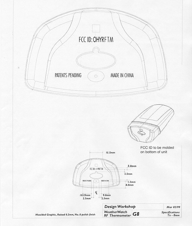
RF99 Wireless Thermometer Feb 23, 1999 Revision: 04 MECHANICAL Component ListXB14 (Mass Market ) PlasticParts Reference Item Description HW part no. Saitek part no. Qty per # of cav. Tool # Color Material Texture Artwork 1 Cover housing (Rx) RxMM-P001 21X250-00100 1 1 1 C1 ABS T2 G1MM 2 Base housing (Rx) RxMM-P002 21X250-00200 1 1 1 C1 ABS T2 G2MM 3 Battery door (Rx) RxMM-P003 21X250-00300 1 1 4 C1 ABS T2 Nil 4 Battery box lid (Rx) RxMM-P004 21X250-00400 1 1 4 C1 ABS T0 & T3 G3 5 Flip stand RxMM-P005 21X250-00500 1 1 2 C1 ABS T2 G10MM 6 Stand end cap RxMM-P006 21X250-00600 1 1 2 C1 ABS T2 Nil 7 Antenna core RxMM-P007 21X250-00700 1 1 4 C2 ABS T0 Nil 8 Antenna end cap RxMM-P008 21X250-00800 1 1 3 C2 ABS T2 Nil 9 Front key tree (Rx) RxMM-P009 21X250-00900 1 1 3 C2 ABS T2 Nil 10 Rear key tree (Rx) RxMM-P010 21X250-01000 1 1 3 C2 ABS T2 Nil 11 Wall mount clip RxMM-P011 21X250-01100 1 1 2 C1 ABS T2 Nil 12 LCD rubber stop RxMM-P012 21X250-01200 5 5 14 - Rubber - Nil 13 Stand stopper cap RxMM-P013 21X250-01300 1 1 4 C1 ABS T0 Nil 14 Front inner cover (Tx) - 21X25B-00100 1 1 11 C2 ABS T2 (G4,G5)MM 15 Rear inner back (Tx) - 21X25B-00200 1 1 11 C2 ABS T2 G6 16 Battery door (Tx) - 21X25B-00300 1 1 11 C2 ABS T2 Nil 17 Key tree (Tx) - 21X25B-00400 1 1 12 C2 ABS T2 G7mm 18 Probe tip - TBD 1 2 13 C1 PC T1 Nil 19 H. sensor cover - TBD 1 1 12 C2 ABS T2 Nil 20 Outer cover - 21X25B-00700 1 1 10 C5 PC T3 & T4 G9 21 Rubber base - 21X25B-00800 1 1 9 C1 Rubber T3 G8MM 22 R-wall mount bracket - 21X25B-01700 1 1 15 C1 PC T2 Nil 23 L-wall mount bracket - 21X25B-01800 1 1 15 C1 PC T2 Nil 24 Antenna end tip (top) - TBD 1 2 13 C1 PC T2 Nil 25 Antenna end tip (bottom) - TBD 1 2 13 C1 PC T2 Nil
Test Report
Master: ktlPT15231 Date: February 23, 1999 KTL Test Report:8R01147.1 Applicant:Millennium Enterprises Limited 2402 Bank of America Tower, Suite 3625 12 Harcourt Road, Central Hong Kong Equipment Under Test:RFTM Transmitter (E.U.T.) FCC ID:OHYRFTM In Accordance With:FCC Part 15, Subpart C For Low Power Transmitters Operating Periodically In The Band 40.66 - 40.77 MHz And Above 70 MHz Tested By:KTL Ottawa Inc. 3325 River Road, R.R. 5 Ottawa, Ontario K1V 1H2 Authorized By: T. Tidwell, Laboratory Manager Date: Total Number of Pages:32 KTL OttawaFCC PART 15, SUBPART C FOR LOW POWER TRANSMITTERS PROJECT NO.: 8R01147.1 EQUIPMENT: RFTM Transmitter FCC ID: OHYRFTM Page 2 of 30 Table of Contents Section 1. Summary of Test Results General Summary of Test Data Section 2. Equipment Under Test General Equipment Information Description of E.U.T. Modifications Incorporated in E.U.T. Theory of Operation Exercise Program Section 3. Equipment Configuration Equipment Configuration List Inter-Connection Cables Configuration of E.U.T. Section 4. Transmission Requirements Test Conditions Test Results Test Data Rationale for Compliance Graphs Section 5. Radiated Emissions Test Conditions Test Results Test Data - Radiated Emissions Radiated Photographs Pre-Scan Data Section 6. Occupied Bandwidth Test Conditions Test Results Test Data Graphs KTL OttawaFCC PART 15, SUBPART C FOR LOW POWER TRANSMITTERS PROJECT NO.: 8R01147.1 EQUIPMENT: RFTM Transmitter FCC ID: OHYRFTM Page 3 of 30 Table of Contents, continued Section 7. Frequency Tolerance Test Conditions Test Results Test Data Section 8. Periodic Alternate Field Strength Requirements Test Conditions Test Results Test Data Section 9. Powerline Conducted Emissions Test Conditions Test Results Test Data Section 10. Block Diagrams Conducted Emissions Radiated Prescan Outdoor Test Site for Radiated Emissions Occupied Bandwidth Section 11. Test Equipment List Annex A - Restricted Bands KTL OttawaFCC PART 15, SUBPART C FOR LOW POWER TRANSMITTERS PROJECT NO.: 8R01147.1 EQUIPMENT: RFTM Transmitter FCC ID: OHYRFTM Page 4 of 30 Section 1.Summary of Test Results Manufacturer:Headwaters Research Model No.:RFTM Serial No.:None General:All measurements are traceable to national standards. These tests were conducted on a sample of the equipment for the purpose of demonstrating compliance with Part 15, Subpart C, Paragraph 15.231. All tests were conducted using measurement procedure ANSI C63.4-1992. Radiated emissions are made on an open area test site. A description of the test facility is on file with the FCC. New SubmissionProduction Unit Class II Permissive ChangePre-Production Unit DS C Equipment Code THIS TEST REPORT RELATES ONLY TO THE ITEM(S) TESTED. THE FOLLOWING DEVIATIONS FROM, ADDITIONS TO, OR EXCLUSIONS FROM THE TEST SPECIFICATIONS HAVE BEEN MADE. See “ Summary of Test Data”. NVLAP LAB CODE: 100351-0 TESTED BY: _____________________________________ DATE: ___________________ Kevin Carr, Technologist KTL Ottawa Inc. authorizes the above named company to reproduce this report provided it is reproduced in its entirety and for use by the company’s employees only. Any use which a third party makes of this report, or any reliance on or decisions to be made based on it, are the responsibility of such third parties. KTL Ottawa Inc. accepts no responsibility for damages, if any, suffered by any third party as a result of decisions made or actions based on this report. This report applies only to the items tested. KTL OttawaFCC PART 15, SUBPART C FOR LOW POWER TRANSMITTERS PROJECT NO.: 8R01147.1 EQUIPMENT: RFTM Transmitter FCC ID: OHYRFTM Page 5 of 30 Summary Of Test Data Name of TestParagraph NumberResults Transmission Requirements15.231(a)Not Applicable Radiated Emissions15.231(b)Not Applicable Occupied Bandwidth15.231(c)Complies Frequency Tolerance15.231(d)Not Applicable Periodic Alternate Field Strength Requirements15.231(e)Complies Powerline Conducted Emissions15.207Not Applicable Footnotes For N/A’s: (1) Equipment complies with 15.231(e). (2) Equipment complies with 15.231(e). (3) Equipment operates at 315 MHz. (4) Equipment is battery powered. Test Conditions: IndoorTemperature: 21 °C Humidity:20 % OutdoorTemperature: 0 °C Humidity:20 % KTL OttawaFCC PART 15, SUBPART C FOR LOW POWER TRANSMITTERS PROJECT NO.: 8R01147.1 EQUIPMENT: RFTM Transmitter FCC ID: OHYRFTM Page 6 of 30 Section 2.Equipment Under Test (E.U.T.) General Equipment Information Frequency Range: 315 MHz (Fixed) Operating Frequency(ies) of Sample: 315 MHz Type of Emission: Pulse Code Modulation Emission Designator: 108KL1D Supply Power Requirement: 2 x AA Size Lithium Batteries Duty Cycle Calculation: Synch Pulse Duration: 9.2 msec Data Pulse Duration:4.8 msec In the worst case 100 msec period there are 4 data pulses and 1 synch. Pulse. Duty Cycle (dB)= 20 log 100 )8.44(2.9x+ = -10.9 dB KTL OttawaFCC PART 15, SUBPART C FOR LOW POWER TRANSMITTERS PROJECT NO.: 8R01147.1 EQUIPMENT: RFTM Transmitter FCC ID: OHYRFTM Page 7 of 30 Description of E.U.T. The E.U.T. is a low power transmitter used to transmit temperature data periodically to its companion receiver. Modifications Incorporated in E.U.T. The EUT has not been modified from what is described by the brand name and unique type identification stated above. KTL OttawaFCC PART 15, SUBPART C FOR LOW POWER TRANSMITTERS PROJECT NO.: 8R01147.1 EQUIPMENT: RFTM Transmitter FCC ID: OHYRFTM Page 8 of 30 Theory of Operation The E.U.T. consists of a CPU / logic circuit based on the MSM64162 IC and the transmitter circuit which is based on a 315 MHz SAW resonator. KTL OttawaFCC PART 15, SUBPART C FOR LOW POWER TRANSMITTERS PROJECT NO.: 8R01147.1 EQUIPMENT: RFTM Transmitter FCC ID: OHYRFTM Page 9 of 30 Justification The E.U.T. was configured for testing as per typical installation. The following combinations were investigated to establish worst case configuration: (1) Transmitter mounted in three orthogonal axis. (2) Sensor cable manipulated in all possible positions. (3) T…
Text truncated - open the document above for the full version.
Contact Information
Applicant
Rudy A. Vandenbelt(Vice President)
01185225220172Fax: 01185225211190
Technical Contact
Non-Technical Contact
KTL OTTAWARUBY C DULMAGE
[email protected]800-563-6336
Test Firm
Nemko Canada Inc.Stuart Beck
Technical Specifications
| # | Rule Parts | Frequency Range | Power Output |
|---|---|---|---|
| 1 | 15C | 315 MHz - 315 MHz | - |