OJJRC73610Wireless Game Pad
Radica Games Ltd.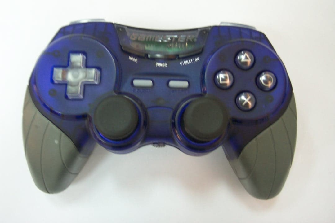
Click to zoom
Application Details
- Equipment Class
- DXT - Part 15 Low Power Transceiver, Rx Verified
- Date of Grant
- May 17, 2004
- Application Purpose
- Original Equipment
- Date of Application
- May 17, 2004
- Equipment Note
- Wireless Game Pad
- Frequency Range
- 2441.00000000 - 2441.00000000
- Company
- Radica Games Ltd.
- Country
- Hong Kong
Documents & Files
Document Text
Text extracted from the exhibit documents filed with the FCC. Open a document above to read the original.
Users Manual
Kc-1203c 2.4GHZ WIRELESS GAME PAD INSTRCTIOIN MANUAL Thank you very much for purchasing the RF game-pad. The RF game-pad is one of peripheral equipments for Sony Playstaion2 console. It has vibration function to provide you more realistic feelings, and complete function keys to set your game-pad more powerful. Before using this controller, please read this manual and retain it for future reference. Specification 1. Compatible with PSX, PS-one, ps2 console 2. This is a ps2 dual shock rumble full analogue RF game pad 3. The pad will come with one host unit. One host unit can use foe one controller. 4. This product will have 8 channels(USA Version), Channels must be matched on both RF pad and the host unit. User can use any channel for any port. All channels are stand-alone. 5. Range up to 10M 6. Battery life-4XAA size alkaline battery – we estimate battery life of approx 60hrs, time will be affect by the shock status and the quality of battery 7. D-pad, X,○,□,△,L1,L2,R1,R2, left and right 3D sticks have analog function 8. Vibration can enable or disable by the user for increase the battery life 9. Designed for short range wireless communication in 2.4ghz – world wide license free band. 10. Power switch and vibration switch for save your power. 11. Dual vibration motor 12. Operation voltage: 3.3V 13. Operation current: 15MA 14. Vibration voltage: 4.5V 15. Vibration voltage: ≤ 70MA Setting the frequency channel Before using your playfree controller, please setting the frequency channel on the controller and receiver so that they match. Controller channel setup 1. Set the switches as shown as shown Receiver setup 1. Set the switches on the side of the receiver as shown Frequency switch configuration The receiver and the remote must be match same channel. Battery install 1. Remove battery compartment cover from the controller 2. Insert 3x1.5V AAA size batteries, observing the correct polarity, we recommend alkaline batteries 3. Refit the battery compartment cover Receiver connection 1. Ensure that your ps2 console is switched off 2. Plug the receiver unit into a controller port on your ps2 controller 3. Turn on your ps2 console Using your playfree controller Switch on the controller by sliding the power on/off, switch to on. Saving battery life, please turn off the controller when you have finished playing BRIEF EXPLANATION OF KEY 1. Q-PAD Manipulates the moving direction of your role in games. 2. FUNCTIONAL KEYS (1) START key can start a game or let game pause. (2) SELECT key allows you to select weapons or tools. 3. VIBRATION MOTOR There is a vibration motor in the D-stick, when you play the feedback games, you feel more real and more comfortable 4. RIGHT AND LEFT 3D STICKS The sticks has analog function, when you play the games that need analog controller, you feel more real and more comfortable. 5. ANOLOG FUNCTION When you press the analog button one time, the ANALOG display LED IS ON, the next button have analog function: D-pad, X, ○,□,△,L1,L2,R1,R2, left and right 3D sticks Precaution of Usage & Storage ● Do not use or store this joystick in an area where is highly moist, dangerous hot, extra- cold or full of dust. ● Do not expose this joystick to direct sunlight for a long time. ● Do not lay this joystick on a surface that is slanted or unstable. ● Do not apply a strong force upon this joystick or drop it roughly from a high place. ● If you want to clean this joystick, you can use a soft cloth, sock it in clean water or diluted neutral detergent, wring out it thoroughly before wiping the dirt from the case. Never use chemicals such as benzene or paint thinner to clean this joystick. NOTE: THE MANUFACTURER IS NOT RESPONSIBLE FOR ANY RADIO OR TV NTERFERENCE CAUSED BY UNAUTHORIZED MODIFICATIONS TO THIS EQUIPMENT. SUCH MODIFICATIONS COULD VOID THE USER AUTHORITY TO OPERATE THE EQUIPMENT.
Block Diagram
Block diagram consolecpu transmiter attenna 4.5V 电 regulator attenna motor Key and Axis cpumodulator
ID Label/Location Info
FCC ID Location FCC ID: OJJRC73610 This device complies with Part 15 of the FCC Rules. Operation is subject to the following two conditions: (1) this device may not cause harmful interference, and (2) this device must accept any interference received, including interference that may cause undesired operation.
Schematics
Title NumberRevisionSize A3 Date:17-Apr-2004Sheet of File:C:\Documents and Settings\CnJazh08\Desktop\Radica_R510_RF24PS2_H_V1.DDBDrawn By: 1 2 3 4 5 6 7 8 9 CN2 PS2 Connector Y1 6MHz C8 22pF C7 22pF OSCI OSCO C2 100nF C1100nF C6 100nF R25 1M C11 100nF C10 47uF C9 1uF L1 220nH R26 1R VCC R14 1M MTR_VCC VCCRF_VCC VCC 1 2 3 4 5 6 CN1 RF Module Connector GND VCC TX/RX RSSI TXD/RXD RF_ACT C12 100nF VCC PF1 2 A V D D 5 2 D V D D 2 0 PA0/KWU8 3 PA1/KWU9 4 PA2/KWUA 5 PA3/KWUB 6 /RST 7 PA4 8 PA5 9 PA6 10 PA7/PWM0 11 P B 0 / K W U 0 1 2 P B 1 / K W U 1 1 3 P B 2 / K W U 2 1 4 P B 3 / K W U 3 1 5 P B 4 / K W U 4 1 6 P B 5 / K W U 5 1 7 P B 6 / K W U 6 1 8 P B 7 / K W U 7 1 9 R F _ A C T 2 1 T X / R X 2 2 R F I O 2 3 D V S S 2 4 AVSS 34 P C 0 / S D I 2 5 P C 1 / S D 0 2 6 PC2/SCK 27 PC3/INT0 28 PC4/INT1 29 PC5/PWM1 30 PLCC 31 OSCO1 32 OSCI 33 PD0/ADC0 35 PD1/ADC1 36 PD2/ADC2 37 P D 3 / A D C 3 3 8 P D 4 / A D C 4 3 9 P D 5 / A D C 5 4 0 P D 6 / A D C 6 4 1 PF0/OSCO2 1 P D 7 / A D C 7 4 2 V r e f 4 3 P E 0 / A D C 8 4 4 P E 1 / A D C 9 4 5 P E 2 / A D C A 4 6 P E 3 / A D C B 4 7 P E 4 / A D C C 4 8 P E 5 / A D C D 4 9 P E 6 / A D C E 5 0 P E 7 / A D C F 5 1 U1 ET44R510 VCC C4 100nF VCC C3 100nF 1 2 3 8 7 6 S? SW DIP-3 R29 200 LED1 GREEN VCC RF signal
Schematics
Title NumberRevisionSize A3 Date:17-Apr-2004Sheet of File:C:\Documents and Settings\CnJazh08\Desktop\Radica_R510_RF24PS2_R_V1.DDBDrawn By: LED1 RED TR2 8051 D2 D4148C11 100nF 1 2 CN5 B_MTR VCC R50 100K R47 1K TR1 8051 D1 D4148 C7 100nF 1 2 CN4 S_MTR R51 100K R48 1K Joy Stick Right2 RV2B Joy Stick Right1 RV2C Joy Stick Left2 RV1B Joy Stick Left1 RV1C VCC VCC VCC VCC RV1 JoyStick_Left RV2 JoyStick Right R5 24K R7 24K R9 24K R11 24K R6 1.5K R8 1.5K R10 1.5K R12 1.5K R1 24K R2 24K R3 24K R4 24K R13 1K5 R14 1K5 R15 1K5 R16 1K5 VCC Y1 6MHzC14 22pF C13 22pF R49 1M SW3 SELECT SW4 START 123 CN2 R19 1K5 R20 1K5 JSR_BTN 123 CN1 R17 1K5 R18 1K5 C9 1000p C8 100nF C5 100nF C17 100nF C16 47uF C15 1uF L1 220nH JSR_BTN VCC R27 1M Radica_R510_RF24PS2_R_V1.0 VCC RF_VCC VCC VCC VCC VCC VCC VCCVCC ( 2222A ) ( 2222A ) R21 200 1 2 3 4 5 6 CN7 RF Module Connector GND VCC TX/RX RSSI TXD/RXD RF_ACT C18 100nF R46 1R L3 LX LY L1L2R1R2 R3 RX RY 1 of 1 C4 10nF PF1 2 A V D D 5 2 D V D D 2 0 PA0/KWU8 3 PA1/KWU9 4 PA2/KWUA 5 PA3/KWUB 6 /RST 7 PA4 8 PA5 9 PA6 10 PA7/PWM0 11 P B 0 / K W U 0 1 2 P B 1 / K W U 1 1 3 P B 2 / K W U 2 1 4 P B 3 / K W U 3 1 5 P B 4 / K W U 4 1 6 P B 5 / K W U 5 1 7 P B 6 / K W U 6 1 8 P B 7 / K W U 7 1 9 R F _ A C T 2 1 T X / R X 2 2 R F I O 2 3 D V S S 2 4 AVSS 34 P C 0 / S D I 2 5 P C 1 / S D 0 2 6 PC2/SCK 27 PC3/INT0 28 PC4/INT1 29 PC5/PWM1 30 PLCC 31 OSCO1 32 OSCI 33 PD0/ADC0 35 PD1/ADC1 36 PD2/ADC2 37 P D 3 / A D C 3 3 8 P D 4 / A D C 4 3 9 P D 5 / A D C 5 4 0 P D 6 / A D C 6 4 1 PF0/OSCO2 1 P D 7 / A D C 7 4 2 V r e f 4 3 P E 0 / A D C 8 4 4 P E 1 / A D C 9 4 5 P E 2 / A D C A 4 6 P E 3 / A D C B 4 7 P E 4 / A D C C 4 8 P E 5 / A D C D 4 9 P E 6 / A D C E 5 0 P E 7 / A D C F 5 1 U1 ET44R510 VCC Analog mode SW5 Analog Rev: 1.0 1 2 CN6 BAT_CN BAT_GND C3 100nF +C1 1uF +C2 10uF VCCBAT V_IN 2 V_OUT 1 G N D 3 Q1 APL5883 BAT S1 SW SPDT TR6 8051 TR5 8051 VCC ( 2222A ) ( 2222A ) R33 2.2M R35 360K R32 2.4M R34 22M low power detect low power detect R29 200 LED2 GREEN VCC Digital mode INVERSE S2 SW SPDT SW6 Vibration 1 2 3 8 7 6 S? SW DIP-3
Test Report
Report No.: 04.03.0653EF Page: 1 of 16 FCC ID: OJJRC73610 Authorized Signature: Kent Hsu Laboratory Manager SGS-CSTC Co.,Ltd. This report refers to the General Conditions for Inspection and Testing Services, printed overleaf This report details the results of the testing carried out on one sample. The results contained in this test report do not relate to other samples of the same product and does not permit the use of the SGS PRODUCT CERTIFICATION MARK.. The manufacturer should ensure that all products in series production are in conformity with the product sample detailed in this report. This report may only be reproduced and distributed in full. If the product in this report is used in any configuration other than that detailed in the report, the manufacturer must ensure the new system complies with all relevant standards. Any mention of SGS International Electrical Approvals or testing done by SGS International Electrical Approvals in connection with, distribution or use of the product described in this report must be approved by SGS International Electrical Approvals in writing. Member of the SGS Group (Société Générale de Surveillance) SGS-CSTC Standards Technical Services Ltd. 1 /F., Building No. 1 Building, Agriculture Machinery Materials Co. Wushan Road, Shipai, Tianhe District,Guangzhou, China Telephone: +86 (0) 20 3848 1001 Fax: +86 (0) 20 3848 1006 [email protected] FEDERAL COMMUNICATIONS COMMISSION Registration number: 282399 FCC TEST REPORT Application No. : 04.03.0653E Applicant: Radica Games Ltd. FCC ID: OJJRC73610 Fundamental Carrier Frequency : 2.441 GHz Equipment Under Test (EUT): Name: PS2 Phoenix Wireless Pad Model: RC73610 Standards: FCC PART 15, SUBPART C : 2002 Date of Receipt: 1 April 2004 Date of Test: 25 April 2004 Date of Issue: 26 April 2004 Test Result : PASS * * In the configuration tested, the EUT complied with the standards specified above. SGS-CSTC Standards Technical Services Ltd. Report No.:04.03.0653EF Page: 2 of 16 FCC ID: OJJRC73610 2 Contents Page 1 COVER PAGE.................................................................................................................................................1 2 CONTENTS.......................................................................................................................................................2 3 GENERAL INFORMATION...........................................................................................................................3 3.1 C LIENT I NFORMATION .................................................................................................................................3 3.2 G ENERAL D ESCRIPTION OF E.U.T................................................................................................................3 3.3 D ESCRIPTION OF S UPPORT U NITS .................................................................................................................3 3.4 S TANDARDS A PPLICABLE FOR T ESTING ........................................................................................................3 3.5 T EST L OCATION ..........................................................................................................................................3 3.6 O THER I NFORMATION R EQUESTED BY THE C USTOMER ..................................................................................3 3.7 T EST F ACILITY ............................................................................................................................................4 4 TEST RESULTS...............................................................................................................................................5 4.1 T EST I NSTRUMENTS .....................................................................................................................................5 4.2 E.U.T. O PERATION .....................................................................................................................................5 4.3 T EST P ROCEDURE & M EASUREMENT D ATA ..................................................................................................6 4.3.1 Radiated Emissions...............................................................................................................................6 4.3.2 Conducted Emissions Mains Terminals, 150kHz to 30MHz..................................................................10 4.3.3 Measurement Data..............................................................................................................................10 4.3.4 Occupied Bandwidth............................................................................................................................11 5 PHOTOGRAPHS - RADIATED EMISSION TEST SETUP........................................................................12 6 PHOTOGRAPHS - EUT CONSTRUCTIONAL DETAILS.....................................................................13~16 SGS-CSTC Standards Technical Services Ltd. Report No.:04.03.0653EF Page: 3 of 16 FCC ID: OJJRC73610 3 General Information 3.1 Client Information Applicant Name: Radica Games Ltd. Applicant Address: Suit V, 6/F, Valiant Ind. Centre., 2-12 Au Pui Wan Street. Fotan, Shatin, N.T. Hong Kong 3.2 General Description of E.U.T. Product Name: PS2 Phoenix Wireless Pad (2.4GHz) Model: RC73610 Power Supply: 4.5V DC (3 x ‘AA’ Size Batteries) for Transmitter, Receiver powered by host PS2. Power Cord: N/A- 3.3 Description of Support Units The EUT was tested as an PS2 (model: SCPH-30006 R of SONY) & TCL 17” TV monitor. 3.4 Standards Applicable for Testing The customer requested FCC tests for a PS2 Phoenix Wireless Pad (Receiver) The standard used was FCC PART 15, SUBPART C (2003) section 15.249. 3.5 Test Location All tests were performed at:- SGS-CSTC Standards Technical Services Ltd., Guangzhou Safety & EMC Laboratory, 1/F, Building No. 1, Agriculture Machinery Materials Company Warehouse Ltd., Wushan Road Shipai, Tian…
Text truncated - open the document above for the full version.
Contact Information
Applicant
Keith Yiu(Engineering Service Manager)
852-2693-2238Fax: 852-2695-9657
Test Firm
SGS-CSTC Standards Technical Services Co., LtdJerry Chan
Technical Specifications
| # | Rule Parts | Frequency Range | Power Output |
|---|---|---|---|
| 1 | 15C | 2.44 GHz - 2.44 GHz | - |
Other Applications from Radica Games Ltd.
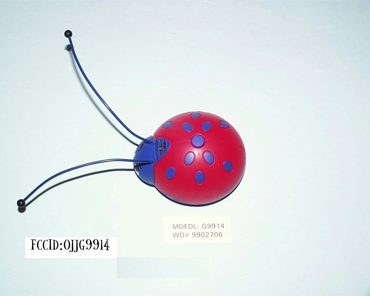
OJJG9914
Jun 24, 1999Bug'EM
Equipment Class
DXX - Part 15 Low Power Communication Device Transmitter