OK3PROXIESCORTEIntelligent Data Collector
Securiton GCS GmbH
Click to zoom
Application Details
- Equipment Class
- DSC - Part 15 Security/Remote Control Transmitter
- Date of Grant
- Aug 10, 1999
- Application Purpose
- Original Equipment
- Date of Application
- Jun 02, 1999
- Equipment Note
- Intelligent Data Collector
- Frequency Range
- 0.12500000 - 0.12500000
- Company
- Securiton GCS GmbH
- Country
- Austria
Documents & Files
Document Text
Text extracted from the exhibit documents filed with the FCC. Open a document above to read the original.
Users Manual
HW - Documentation Proxi-ESCORTE page 1 Hardware - Documentation Proxi-ESCORTE 1 Functional description 1.1 Basic functionality The basic function of the Standard ESCORTE is that of an intelligent data collector: Every time a GCS data strip is read in correctly, the Data Acquisition Unit (DAU) recognises the unique 8- digit number encoded in the strip and stores this number together with the time and date of the reading in its memory. Then you can either transfer the data to a computer for further processing using a Data Transfer Unit (DTU) or have the data evaluated in the DAU itself and check the results in the form of well structured printouts. Proxi–ESCORTE in addition offers the possibility to read transponders (also called tags), too. Further processing is the same as reading a data strip. 1.2 How it works Data strips consist of a carrier made of plastic and a ferromagnetic tape on the top of the carrier. During the production process the barcode is mechanically engraved into the tape. The code represents an 8 digit decimal number plus checksum. In order to record a data strip the reading head of the Proxi–ESCORTE must be wiped over the strip without applying to much pressure. During scanning the strip a permanent magnet placed in the reading head magnetizes the ferromagnetic tape. At the same time a magnetic reading head system which is mounted in the reading head of the Proxi–ESCORTE with a cardanic suspension picks up the magnetic field emitted by the magnetic tape. A specially designed circuit amplifies the weak signal of the magnetic head and provides a digital signal for further processing. Processing of incoming data is done by a micro-controller. Correct readings will be acknowledged by the unit with an acoustic and an optical signal (the LEDs will flash). Proxi–ESCORTE additionally offers the possibly to read and also write transponders (tags). Transponders contain an integrated circuit (chip) and an antenna – they are typically shaped as discs. The chip contains an 8 digit identification code. In order to read out data from the chip it is necessary to first position the head of the Proxi–ESCORTE in a maximum distance of about 1” above the tag and then shortly press the button placed at the top of the device. This will trigger the system and the transponder communication process will start. First a magnetic field is build up by the antenna coil which is placed in the fixed part of the reading head of the Proxi– ESCORTE. Then the transponder accumulates energy which it picks up with its antenna from the radiated field of the Proxi–ESCORTE and starts to send data by load modulation. Load modulation is detected by a special integrated circuit (reader ASIC) and a digital signal is output. Further signal processing is done by the micro-controller. Data sent to the transponder is ASK modulated. An additional feature of the tags versus data strips is the write function. Read only transponders can only be read, read/write transponders store the unit’s serial number, time and date of the last reading in a nonvolatile memory. This information may later on be read locally by another unit, e.g. by a supervisor, no access to a database is needed. The mode of operation is set by a flag in the transponder memory and can be altered by GCS. The flag may be ignored if the Proxi- ESCORTE is set to do so. The transponder communication process for writing tags is quite similar to reading tags. The main difference is that during programming the nonvolatile memory HW - Documentation Proxi-ESCORTE page 2 more energy is needed by the transponder than for reading it. Therefore the maximum communication distance for writing is less than for reading. The user has to keep in mind that strong electromagnetic fields may have an adverse effect on the reading of data strips and tags, and that they shorten the lifetime of the power pack. Communication between the DTU and the Proxi–ESCORTE is done wireless by inductive coupling. There are separate coils for transmitting and receiving data. Proxi–ESCORTE is powered by three alkaline batteries put together in a battery pack. For normal use this pack usually lasts for one to two years. 1.3 Parts of the Proxi-ESCORTE The device consists of three main parts • electronic part The case/body consists of two plastic parts which are glued together. Inside there are 3 PCBs: - the reading head board with the magnetic head signal amplifier, the LEDs and the buzzer on it - the analog print with the circuitry for the wireless interface to the DTU, the circuits for transponder communication and other peripheral analog circuits on it - and the digital print with the micro-controller, memory and ‘glue logic’ on it. • the reading head The reading head is attached to the electronic part/body and should only be removed by authorized persons. To remove the head first two plastic rivets have to be extracted using a special tool. The reading head consists of: - a fixed part which is attached to the electronic part/body (as described above) where the antenna for the transponder communication is integrated - a cardanic suspension for the reading head system - the reading head system to read the magnetized strips (also containing a small permanent magnet to first magnetize the strips) • the power pack The power pack is attached to the electronic part/body and should only be removed by authorized persons. To remove the battery first two small round plastic parts have to be removed. Then access to two screws is possible, they have to be turn out. Lastly two plastic rivets have to be extracted using a special tool – similar to the reading head. HW - Documentation Proxi-ESCORTE page 3 2 block diagram showing all relevant clock frequencies transponder communic. circuit magnetic barcode reader Microcontroller RAM EEPROM inductive interface power supply 3V/ 5V(DCDC) 6MHz 4MHz 125kHz 600kHz (Transmit) 800kHz (Receive) 3cells Most functions are performed by the micro-controller (80C154) opera…
Text truncated - open the document above for the full version.
Block Diagram
transponder communic. circuit magnetic barcode reader Microcontroller RAM EEPROM inductive interface power supply 3V/ 5V(DCDC) 6MHz 4MHz 125kHz 600kHz (Transmit) 800kHz (Receive) 3cells Proxi-Escorte Block Diagram
Cover Letter(s)
EMC Automation 1101 CYPRESS CREEK RD • CEDAR PARK TX 78613 • USA PHONE: (+1) 512-258-9478 • FAX: (+1) 512-258-0740 WWW.EMC-AUTOMATION.COM A TDK Group Company Federal Communications CommissionJune 11, 1999 Office of Engineering and Technology Equipment Authorization Division, Customer Service Branch 7435 Oakland Mills RD Columbia, MD 21046 Confirmation Number: EA93833 FCC ID: OCQLA-WIWPROXKEYM To Whom It May Concern: My name is Michael E. Hill. I am the Manager-Test Facility for EMC Automation. We recently tested the Securiton GCS GmbH Proxi ESCORTE data collection system to CFR47 Part 15. The device is an intentional radiator (125KHz). As such, it requires certification with the FCC. It is our opinion this device conforms to the requirements of Part 15. The sample tested met these standards without modification. On behalf of ISI and their representative Herbert Newald, EMCA is handling the Form 731 filing for this product. This is an electronic submittal. Form 731 has been filed electronically, Form 159 printed and the necessary payment have been mailed to the FCC. Securiton requests that certain details of the design be kept confidential. The design features Securiton wants confidential have been marked in electronic FCC filing. Any questions regarding this submittal (i.e. missing information), should be forwarded to me. Please feel free to use my email address: [email protected]. As this is our first electronic filing, EMCA would appreciate any comments you may have that will expedite this process in the future. Sincerely, Manager Test Facility Cc: Herbert Newald Securiton
Cover Letter(s)
EMC Automation 1101 CYPRESS CREEK RD • CEDAR PARK TX 78613 • USA PHONE: (+1) 512-258-9478 • FAX: (+1) 512-258-0740 WWW.EMC-AUTOMATION.COM A TDK Group Company Federal Communications CommissionJuly 14, 1999 Office of Engineering and Technology Equipment Authorization Division, Customer Service Branch 7435 Oakland Mills RD Columbia, MD 21046 Confirmation Number: EA94419 FCC ID: OK3PROXIESCORTE To Whom It May Concern: EMC Automation recently tested the Securiton GCS GmbH Proxi ESCORTE data collection system to CFR47 Part 15. The device is an intentional radiator (125KHz). As such, it requires certification with the FCC. It is our opinion this device conforms to the requirements of Part 15. The sample tested met these standards without modification. On behalf of ISI and their representative Herbert Newald, EMCA is handling the Form 731 filing for this product. This is an electronic submittal. Form 731 has been filed electronically, Form 159 printed and the necessary payment have been mailed to the FCC. Per CFR47, section 0.459(b), Securiton requests that certain details of the design be kept confidential. The design features Securiton wants confidential have been marked in electronic FCC filing. These design details illustrate certain innovations Securiton considers proprietary. Securiton does not want its competitors to have access to this information. Any questions regarding this submittal (i.e. missing information), should be forwarded to me. Please feel free to use my email address: [email protected]. Your attention in this matter is appreciated. Sincerely, Manager Test Facility Cc: Herbert Newald Securiton
ID Label/Location Info
EMC Automation 1101 CYPRESS CREEK RD • CEDAR PARK TX 78613 • USA PHONE: (+1) 512-258-9478 • FAX: (+1) 512-258-0740 WWW.EMC-AUTOMATION.COM A TDK Group Company FORM 731 ATTACHMENT Label Confirmation Number: EA94419 FCC ID: OK3PROXIESCORTE A label will be permanently attached to the product under the battery pack. The label will look like: The actual label will have the devices correct FCC ID instead of ‘1234567890’. In addition, product literature will also state: This device complies with part 15 of the FCC Rules. Operation is subject to the fol- lowing two conditions: (1) This device may not cause harmful interference, and (2) this device must accept any interference re- ceived, including interference that may cause undesired operation .
Test Report
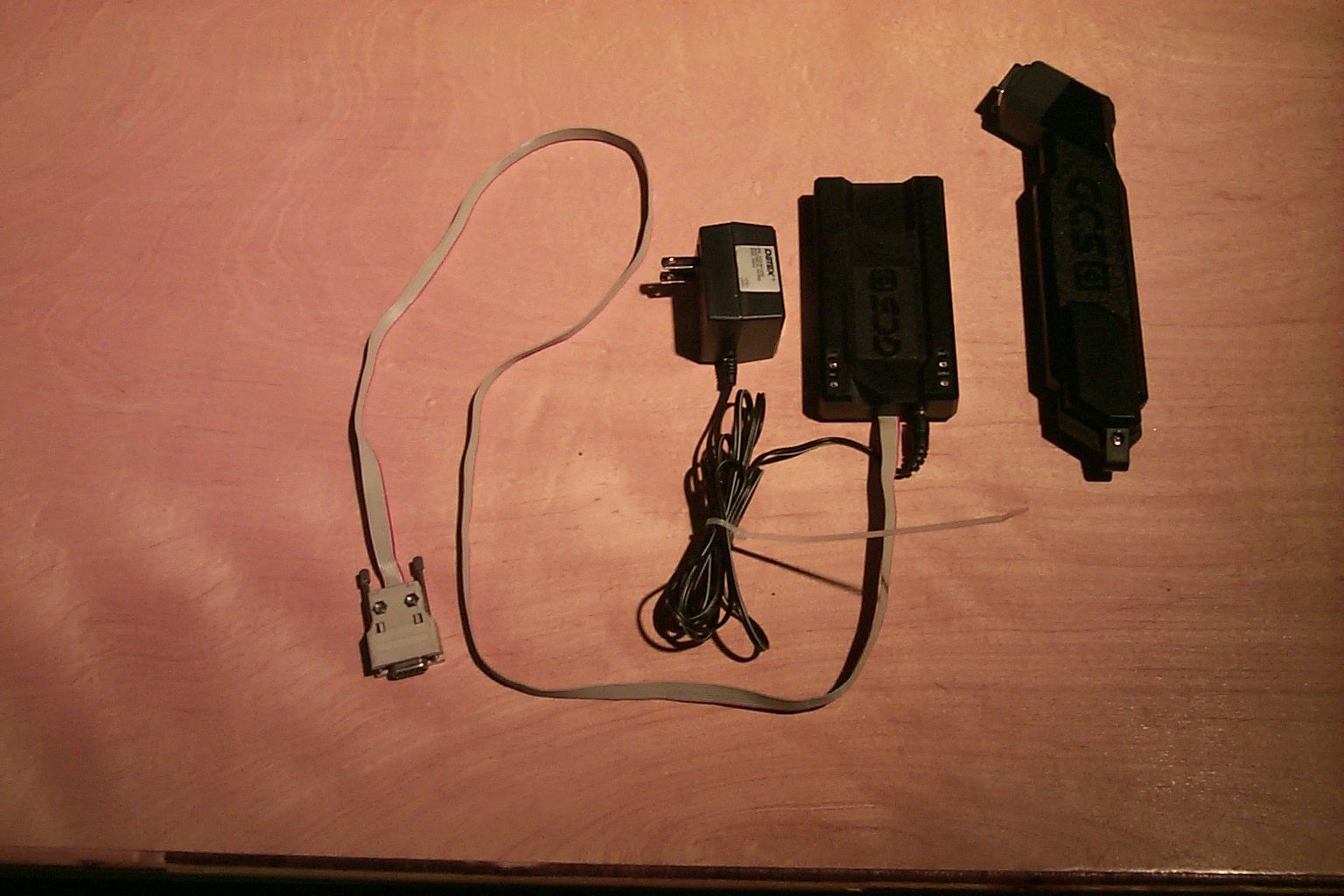
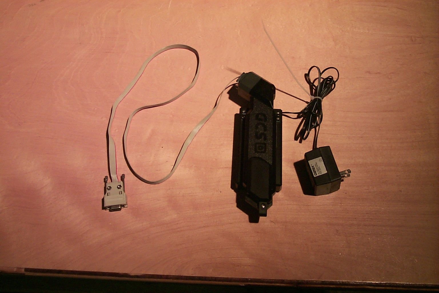
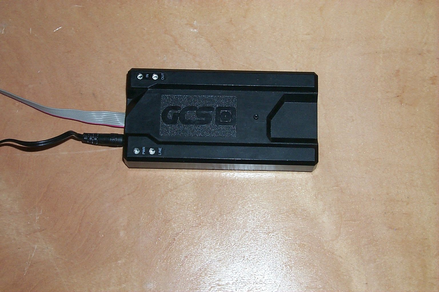
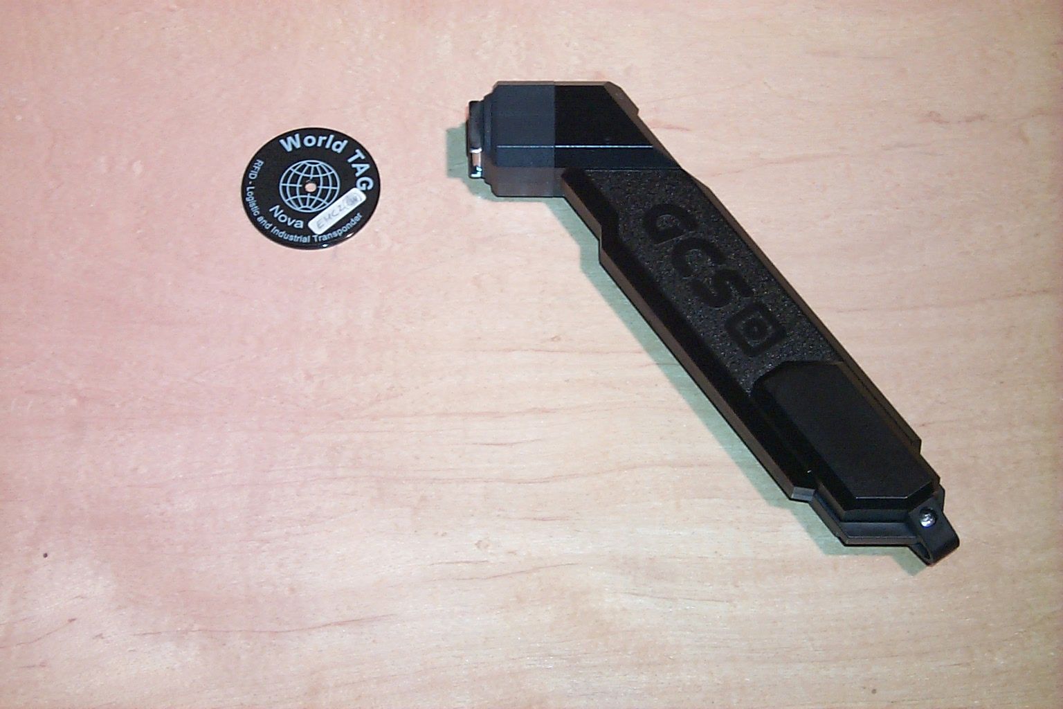
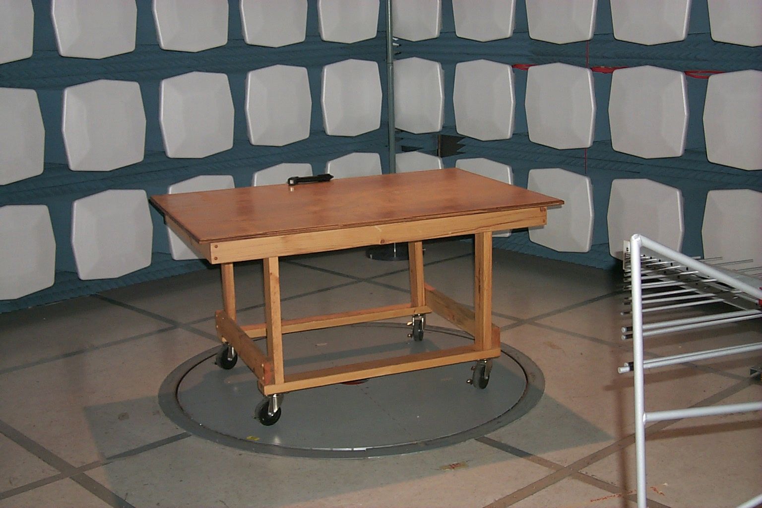
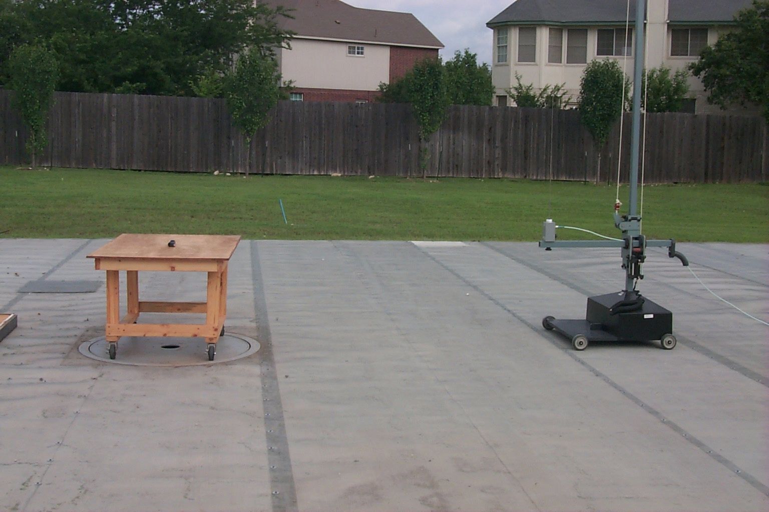
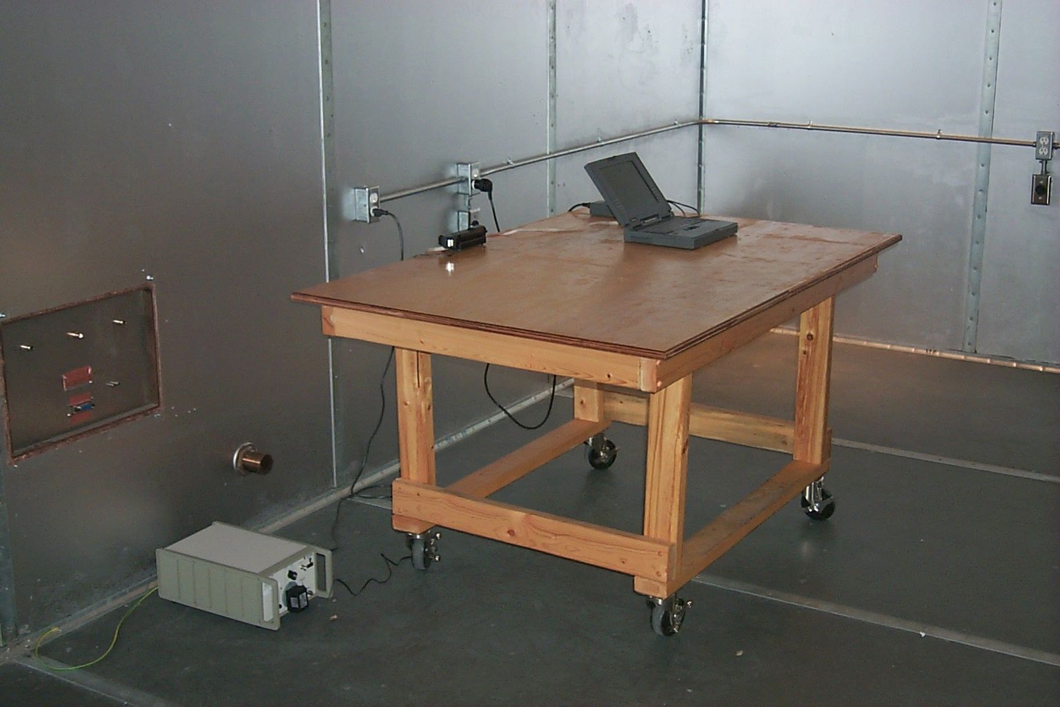
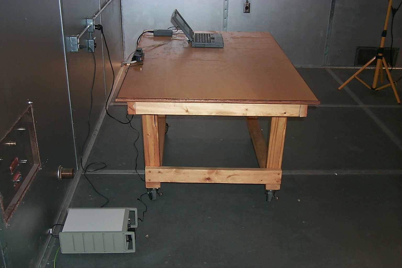
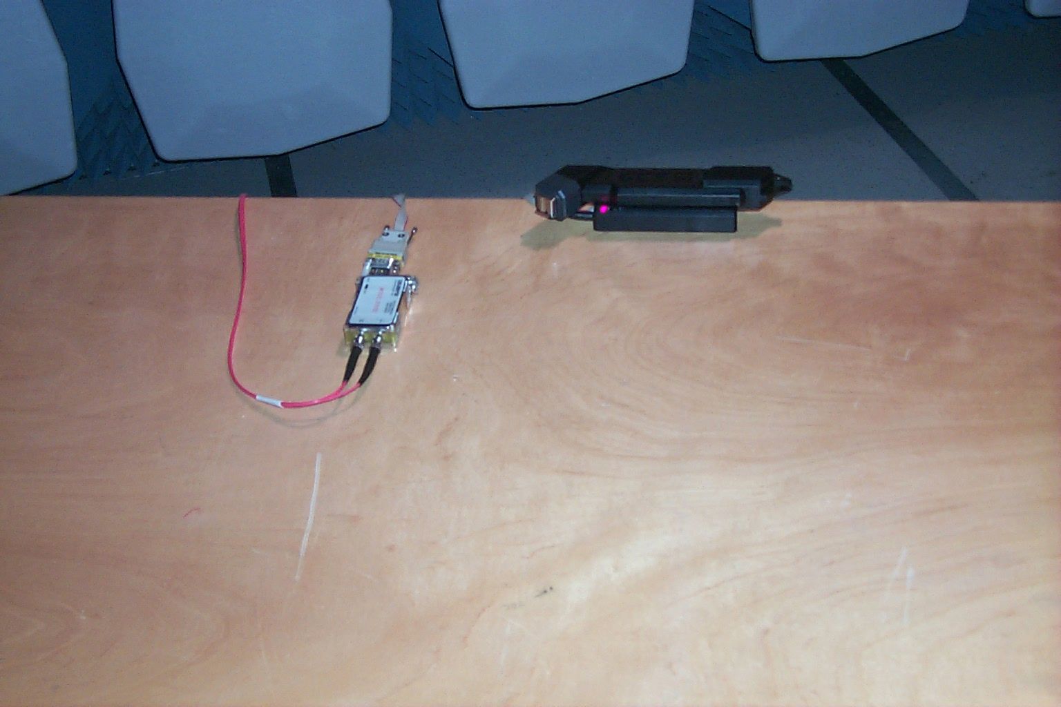
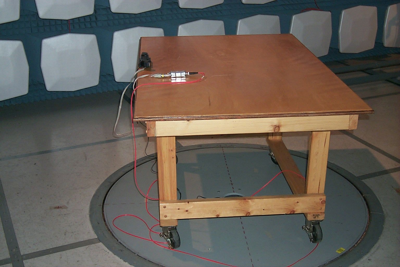
EMC Automation EMCA Test Report: GCS0001-99 1.0 PURPOSE This test report applies to the Securiton GCS GmbH (GCS) PROXI ESCORTE Data Acquisition Unit (DAU) and it’s Transmission Data Unit (TDU). (See Fig. 1.) The device has a wide range of applications but is initially intended to replace the mechanical clock/key system currently used by security guards on their rounds. Rather than a bulky heavy clock, the guard would pass the battery-operated DAU across an encoded ferro-magnetic data strip or a transponder TAG. The code number on the strip and the time would be loaded into the DAU. Once the guard has completed making rounds the DAU memory can be downloaded into a computer via the line- powered TDU. Figure 1 The purpose of this electromagnetic compatibility (EMC) Test Report is to give the FCC information on the radiated emission profile of the data acquisition unit as required for 47 CFR Ch. I (10-1-97 Edition) Part 15-Radio Frequency Devices, Subpart C-Intentional Radiators and Subpart B-Unintentional Radiators. For sake of brevity, this standard will be referred to as FCC Part 15. The data acquisition unit is an intentional radiator designed to operate at 125KHz. It emits a weak RF field to activate the transponder. Obviously, it is a Subpart C device. Since the TDU/data acquisition units contain microprocessors (operating at 6MHz) and the TDU can be part of a distributed network, it is a computer peripheral and is subject to Subpart B levels also. FCC Part 15 testing is performed using the techniques and practices described in the “American National Standard for Methods of Measurement of Radio Noise Emission from Low-Voltage EMC Automation EMCA Test Report: GCS0001-99 Electrical and Electronic Equipment in the Range of 9KHz to 40GHZ”, ANSIC63.4-1992. The target emissions levels are set using criterion set in FCC Part 15. The data acquisition unit is powered by batteries therefore no conducted emissions testing was necessary for the unit itself. However the TDU is a line-powered device designed to operate only in conjunction with the DAU. Conducted emissions testing in this configuration was necessary. 2.0 EQUIPMENT 2.1 GCS Supplied Equipment All tests described below were carried out on a system comprised of standard production units. The equipment defined below was available solely for the purposes of EMC testing during the test program. Description ProxiEscorte Data Acquisition Unit, TAGS transponders Transmission Data Unit In addition to the above, Securiton supplied software and a notebook computer that continually exercised the hardware via a fiber-optic link in order to maximize emissions. They also supplied an unpotted version of the device allowing disassembly. Photos of this particular unit are to be included with the FCC Form 731 submittal. EMC Automation EMCA Test Report: GCS0001-99 2.2 EMCA Test Equipment Name and Model Number Serial NumberCalibratedNext Calibration Hewlett-Packard HP8546A Receiver 3520A00237 3448A00238 13 Oct. 199813 Oct. 1999 EMCO 3810/2 EMCO Passive Monopole 3303 Antenna 10KHz-30MHz 9903-30422 Mar.199922 Mar.2000 EMCO Biconilog 3142 Antenna 30MHz-1GHz 9706-110417 Feb. 199917 Feb. 2000 Transformer/Adapter U.S. 110Vac to European 220Vac N/AN/AN/A 3M Semi-anechoic Chamber and Associated H/W (turntable, antenna mast, etc.) N/AN/AN/A EMCO 3810/2 Line Impedance Stabilization Network 1823May 25,1999May 25, 2000 EMCO 2075 Minimast9707-2061N/AN/A EMC Automation EMCA Test Report: GCS0001-99 EMCO 2090 Multi-Device Controller 9704-1231N/AN/A Pentium-based PC system N/AN/AN/A EMCA Radiated Emissions S/W Ver. 7.33 N/AN/AN/A 3.0 PROCEDURE and RESULTS 3.1 Equipment Configuration The dates of the testing were June1 & 2,1999. Testing was done in the semi- anechoic chamber, the shield room and the 10m Open Area Test Site (OATS). At all sites, the data acquisition unit was placed on a wooden (non-conductive) table, 80cm high. On the emissions sites, the table was placed on a turntable. The equipment was arranged in the manner recommended in Fig 9(c) Test Configuration Tabletop Equipment Radiated Emissions of ANSI C63.4-1992. EMC Automation EMCA Test Report: GCS0001-99 Figure 2 Figure 2 shows the test setup. The DAU only fits one way on TDU. The transmit data unit was connected via an orange fiber-optic line to a computer located outside the semianechoic chamber. Figure 3 shows the data acquisition unit when it was tested by itself in TAG mode. The antenna is a biconilog good for the range 26MHz-2000MHz. The DAU head was held less than 1” from the TAG and the button depressed. The TAG was removed but device continued to transmit as evidenced by a “ticking” sound and flashing LEDs. A signal could be seen at the display by holding the data acquisition unit close (<2 ft.) to the monopole antenna. EMC Automation EMCA Test Report: GCS0001-99 Figure 3 3.2 Environment The temperature/humidity in the semianechoic chamber and the shield room was as follows: Temperature 20°C Humidity30% The temperature/humidity on the OATS was as follows: Temperature24°C Relative Humidity54 3.3 Radiated Emissions 3.3.1 Preliminary Scan Figure 4 shows the frequency range and the limit line determined from the device transmitting and clock frequencies as determined by review of Part 15. The limits were set for 3m. The test was computer driven/monitored. For prescans, the antenna was set at 1m, the turn table was rotated in 90° increments. The antenna was then raised to a height of 2m and the turntable was rotated in 90° increments. This was repeated for 3m and 4m. Initial sweeps were done with the antenna in vertical then horizontal EMC Automation EMCA Test Report: GCS0001-99 polarity. The maximum peak value for each frequency was stored in computer memory and graphed. Figure 4 All initial scanning was done in the semi-anechoic chamber. During the initial scans, the exact frequencies emitted by the EUT were identified. Initial scans used the Peak Detector. Any frequencies within 10dBuV of the limit lin…
Text truncated - open the document above for the full version.
Contact Information
Applicant
Markus Leiner(Engineer)
Technical Contact
Non-Technical Contact
SECURITON GCS GmbHHerbert Newald
[email protected]++43 1 31361 0
Test Firm
TDK RF Solutions, Inc.Michael Hill
Technical Specifications
| # | Rule Parts | Frequency Range | Power Output |
|---|---|---|---|
| 1 | 15C | 0.125 MHz - 0.125 MHz | - |
Other Applications from Securiton GCS GmbH

OK3PENDTUSER
Aug 09, 2001Proxipen Data Terminal Unit
Equipment Class
DCD - Part 15 Low Power Transmitter Below 1705 kHz
OK3PROXIPEN
Aug 09, 2001Battery Powered Data Collection Device
Equipment Class
DCD - Part 15 Low Power Transmitter Below 1705 kHz