OK7YC1L-YC12Electronic Yard Fence Sensor
Daka Development Ltd.
Click to zoom
Application Details
- Equipment Class
- DXX - Part 15 Low Power Communication Device Transmitter
- Date of Grant
- Aug 13, 2003
- Application Purpose
- Original Equipment
- Date of Application
- Aug 13, 2003
- Equipment Note
- Electronic Yard Fence Sensor
- Frequency Range
- 914.00000000 - 914.00000000
- Company
- Daka Development Ltd.
- Country
- Hong Kong
Documents & Files
Document Text
Text extracted from the exhibit documents filed with the FCC. Open a document above to read the original.
Block Diagram
1234 A B C D 4321 D C B A APPD DAKA DEVELOPMENT LIMITED TITLE DFTS REV SHT OF DRAWING NO. YC12/1L BLOCK DIAGRAM 00 Transducer Ultrasonic Oscillator Amplifier/Compare Strobe light RF Transmitter/Receiver Power Supply
ID Label/Location Info
FCC ID: OK7YC1L-YC12 ——————————————————————————————————————————————— Advanced Compliance Lab 6 Randolph Way, Hillsborough, NJ 08844 Tel: (908) 927-9288 Fax: (908) 927-0728 8 2. PRODUCT LABELING Figure 2.1 FCC ID Label Figure 2.2 Location of Label on the Side of EUT FCC ID: OK7YC1L-YC12 This device complies with part 15 of the FCC Rules. Operating is subject to the following two conditions: (1) This device may not cause harmful interference, and (2) this device must accept any interference received, including interference that may cause undesired operation. Figure 2.1 FCC ID Label Figure 2.2 Location of the Label on EUT Back FCC Label
Operational Description
YC1L-YC12 operation theory Objective: Any objected movement nearby the unit would activate an audible or Ultrasonic sound and/or flashlight. (1) The transistor Q1 and associate components generated a 914MHz high frequency radio wave and emit through the attenta. (2) Any object movement nearby the unit will alter the emit 914Mhz frequency slightly and pick up (using the same attenta) by the unit. These shifted in frequency will be amplify and compared by D1 & IC U2 (plus associated circuit), which will generated a “triggering signal”. (3) The triggering signal will activated IC U5 (an oscillator device). Which is used to drive the output transducer giving an audible or ultrasonic sound and/or flash light. (4) 6V DC or AC adaptor can operate unit.
Test Report
ELECTROMAGNETIC EMISSION COMPLIANCE REPORT of ELECTRONIC YARD FENCE SENSOR MODEL: YC1L-YC12 FCC ID: OK7YC1L-YC12 July 25, 2003 This report concerns (check one): Original grant x Class II change Equipment type: Low Power TRANSMITTER Deferred grant requested per 47 CF 0.457(d)(1)(ii)? yes no x If yes, defer until: (date) Company agrees to notify the Commission by (date) of the intended date of announcement of the product so that the grant can be issued on that date. Transition Rules Request per 15.37? yes no x If no, assumed Part 15, Subpart B for unintentional radiators - the new 47 CFR [10-1-90 Edition] provision. Report prepared for: Daka DEVELOPMENT LTD. Report prepared by: Advanced Compliance Lab Report number: 0048-030622-01 The test result in this report IS supported and covered by the NVLAP accreditation 6 Randolph Way Hillsborough, NJ 08844 Tel: (908) 927 9288 Fax: (908) 927 0728 Advanced Compliance Laboratory FCC ID: OK7YC1L-YC12 ——————————————————————————————————————————————— Advanced Compliance Lab 6 Randolph Way, Hillsborough, NJ 08844 Tel: (908) 927-9288 Fax: (908) 927-0728 2 Table of Contents Report Cover Page .........................................................................................................1 Table of Contents ...........................................................................................................2 Figures.............................................................................................................................3 1. GENERAL INFORMATION ...................................................................................4 1.1 Verification of Compliance .........................................................................4 1.2 Equipment Modifications............................................................................5 1.3 Product Information....................................................................................6 1.4 Test Methodology.........................................................................................6 1.5 Test Facility ..................................................................................................6 1.6 Test Equipment ............................................................................................6 1.7 Statement of the Document Use..................................................................7 2. PRODUCT LABELING............................................................................................8 3. SYSTEM TEST CONFIGURATION ......................................................................9 3.1 Justification ..................................................................................................9 3.2 Special Accessories.......................................................................................9 3.3 Configuration of Tested System .................................................................9 4. SYSTEM SCHEMATICS ........................................................................................12 5. CONDUCTED EMISSION DATA ..........................................................................13 5.1 Test Methods and Conditions .....................................................................13 5.2 Test Data .......................................................................................................13 6. RADIATED EMISSION DATA ...............................................................................15 6.1 Field Strength Calculation ..........................................................................15 6.2 Test Methods and Conditions .....................................................................15 6.3 Test Data .......................................................................................................15 6.4 Occupied Bandwidth ...................................................................................16 7. PHOTOS OF TESTED EUT ....................................................................................18 FCC ID: OK7YC1L-YC12 ——————————————————————————————————————————————— Advanced Compliance Lab 6 Randolph Way, Hillsborough, NJ 08844 Tel: (908) 927-9288 Fax: (908) 927-0728 3 Figures Figure 2.1 FCC ID Label...............................................................................................8 Figure 2.2 Location of Label on Back of the EUT ......................................................8 Figure 3.1 Radiated Front ............................................................................................10 Figure 3.2 Radiated Rear .............................................................................................10 Figure 3.3 Conducted Front.........................................................................................11 Figure 3.4 Conducted Rear/Side..................................................................................11 Figure 4.1 System Schematics .....................................................................................12 Figure 5.1 Neutral Conducted Emission.....................................................................14 Figure 5.2 Line Conducted Emission ..........................................................................14 Figure 6.1 Occupied Bandwidth ...................................................................................17 Figure 7.1 Front View....................................................................................................19 Figure 7.2 Rear View w/ AC-DC Adaptor ...................................................................20 Figure 7.3 Inside View, Cover Opened ........................................................................21 Figure 7.4 PCB1 Component Side ................................................................................22 Figure 7.5 PCB1 Foil Side .............................................................................................23 Figure 7.4 PCB2 Component Side ............................…
Text truncated - open the document above for the full version.
Test Setup Photos
FCC ID: OK7YC1L-YC12 ——————————————————————————————————————————————— Advanced Compliance Lab 6 Randolph Way, Hillsborough, NJ 08844 Tel: (908) 927-9288 Fax: (908) 927-0728 10 Figure 3.1 Radiated Front Figure 3.2 Radiated Rear FCC ID: OK7YC1L-YC12 ——————————————————————————————————————————————— Advanced Compliance Lab 6 Randolph Way, Hillsborough, NJ 08844 Tel: (908) 927-9288 Fax: (908) 927-0728 11 Figure 3.3 Conducted Front Figure 3.4 Conducted Rear/Side
Contact Information
Applicant
Pat Mah(Director)
Test Firm
Advanced Compliance LaboratoryWei Li
Technical Specifications
| # | Rule Parts | Frequency Range | Power Output |
|---|---|---|---|
| 1 | 15C | 914 MHz - 914 MHz | - |
Other Applications from Daka Development Ltd.
OK7PC36
Sep 28, 2005Super Bark Free Transmitter PC36
Equipment Class
DSC - Part 15 Security/Remote Control Transmitter
OK7PP10TX
Mar 28, 2004Pet Chime Transmitter
Equipment Class
DSC - Part 15 Security/Remote Control Transmitter
OK7PP10RX
Mar 28, 2004Pet Chime Receiver
Equipment Class
CRR - Superregenerative Receiver
OK7MO10
Jul 10, 2000Bird Monitor
Equipment Class
DSC - Part 15 Security/Remote Control Transmitter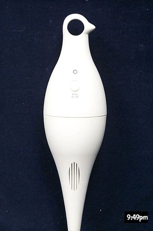
OK7MO20
Jul 10, 2000Bird monitor
Equipment Class
DSC - Part 15 Security/Remote Control Transmitter