OKDTX99
Lovett's Electronics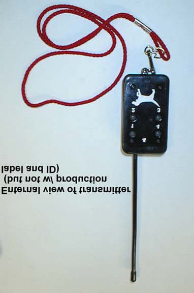
Click to zoom
Application Details
- Equipment Class
- DSC - Part 15 Security/Remote Control Transmitter
- Date of Grant
- Jun 14, 1999
- Application Purpose
- Original Equipment
- Date of Application
- May 11, 1999
- Frequency Range
- 417.80000000 - 418.20000000
- Company
- Lovett's Electronics
- Country
- United States
Documents & Files
Document Text
Text extracted from the exhibit documents filed with the FCC. Open a document above to read the original.
Users Manual
HT99 & LT99 BEEPER /TRAINER COMBO INSTRUCTIONS & WARRANTY INFORMATION The HT99 and LT99 beeper/trainer combo is a new approach to an all in one unit. It is a fully integrated system that uses some of the built-in motion detector features of a beeper to control the trainer. It can be programmed by the user to not allow it to shock if the dog is standing still (on point), which is one of the easiest ways to ruin a good bird dog. It is compact, lightweight and both the receiver and transmitter units are completely waterproof. It is built in the USA under close inspection an tight quality control. WARRANTY Lovett’s Electronics warrants these units to be free of defects in materials and workmanship for a period of one year. Lovett’s Electronics will promptly repair or replace, as it deems most suitable, any product which is defective in material or workmanship without charge for parts and labor provided the product is returned to : Lovett’s Electronics 840 E. Pinckley St. Brazil, Indiana 47834 (812) 446-1093 All costs associated with the shipment of the product is the responsibility of the purchaser. Enclose $6.00 for shipping and handling and a dated copy of receipt or cancelled check. This warranty does not cover defects caused by improper handling, maintenance or abnormal use, alterations or accidents 1.) CHECK FOR IRRITATION ON A REGULAR BASIS. Even though the shock probes are blunt, some dogs can get irritated in as little as 2 days of constant use. If your dog is of the stubborn type and has to wear it all of the time, shift it around on different parts of the neck. 2.) Do not use on a dog if another dog is in the same kennel. Dogs love to chew on things and a chewed collar is not covered under warranty and is usually not repairable. 3.) We need to stress the fact that you install the battery as per instructions. Terminal end (snap end) first then push on the rear until it’s seated in the compartment. The battery pads are very reliable and should last indefinitly if you follow the instructions. Putting the battery straight in will fold over the nickle foil and require repairs. 4.) Remember to use only DURACELL brand batteries. Any good alkaline battery will work, but we have molded this unit for Duracell battery dimensions. A longer battery will deform the contact pads. If you choose to use another brand, stay with the type you selected or one of equal length. PLEASE READ THESE VERY IMPORTANT NOTES
Users Manual
COMBO FEATURES * Three levels of shock voltage and beeper activated at the transmitter. * 16 user selectable ID codes * External, waterproof ON/OFF switch molded in the receiver unit, can be turned on and off without turn-on plugs or magnets. The transmitters momentary pushbuttons are waterproof also. * Top mounted speaker. * Speaker wiring embedded in collar. * Battery makes connection thru nickel plated silicon pads in both units, which eliminates battery clips and broken wires. * Programming instructions are printed on the bottom side of the cover plates of both units in case the instructions are lost. * Spare cover plate screws are included in the battery compartment of both units * Both units use readily available 9 volt Duracell batteries. * Blunt stainless steel shock probes for less irritation TESTING THE UNIT Press the gray rubber dome on the receiver with enough force to hear or feel a click. Then push button labeled BEEPER on the transmitter, you will hear the beeper. Attach the test light cups to the shock probes. While shaking the receiver up and down and the speaker pointing upward (as if hanging on a dogs neck) press LOW, MED, then HIGH. The test light should glow at different brightness accordingly. Holding the receiver still for 10 seconds will allow the point signal to kick in and will beep one beep every other second for as long as it’s held still. Pressing the switch dome again turns the unit off. All units are shipped programmed in the “no shock on point” mode with the point beep turned on. When the dog is running all four functions will work, LOW, MED and HIGH shock and the BEEPER button for locating the dog in cover. When the dog is on point, none of the functions will do anything since it won’t shock on point and the beeper is beeping anyway. PROGRAMMING THE UNITS For battery replacement and access to the programming dip switch, remove the four bottom coverplate screws and remove the cover plate. Remove the battery by pulling on the nylon tape pull tab. The transmitter switch has 6 positions and the receiver has 8. Switches 1 thru 4 on both units can be any combination of OFF or ON but they must match . These are your 16 different ID codes. Switches 5 and 6 on the transmitter do nothing. Switches 5 & 6 on the receiver work together to defeat the ”no shock on point” feature. Both ON results in shock any time, both OFF results in “no shock on point”. Switch 7 does nothing (reserved for 2 dog unit). Switch 8 OFF turns the automatic point signal OFF. The beeper will still sound if the transmitter BEEPER button is pushed but no auto point signal after 10 seconds delay. REMEMBER! INSTALL THE DURACELL BATTERY TERMINAL (SNAP END) FIRST AS SHOWN IN FIGURE ABOVE. Battery Contact Spare Pads Screws Programming switch _ + PLEASE NOTE THAT ONE BATTERY PAD IS LARGER THAN THE OTHER. THE LARGER ONE IS NEGATIVE AND THE SMALLER IS POSITIVE.
Contact Information
Applicant
Henry R Lovett(Owner)
Test Firm
Smith Electronics, Inc.James Pollock
Technical Specifications
| # | Rule Parts | Frequency Range | Power Output | Tolerance |
|---|---|---|---|---|
| 1 | 15C | 417.8 MHz - 418.2 MHz | - | Hz |