OKKNMX920Mobitex Transmitter Module
Nomadic Communications PTY Ltd.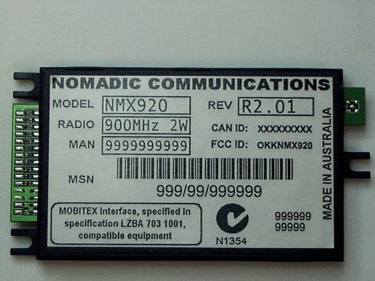
Click to zoom
Application Details
- Equipment Class
- TNB - Licensed Non-Broadcast Station Transmitter
- Date of Grant
- Jun 15, 2000
- Application Purpose
- Original Equipment
- Date of Application
- Feb 14, 2000
- Equipment Note
- Mobitex Transmitter Module
- Frequency Range
- 895.00000000 - 905.00000000
- Country
- Australia
Documents & Files
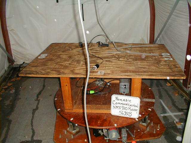
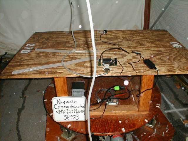
Document Text
Text extracted from the exhibit documents filed with the FCC. Open a document above to read the original.
Users Manual
NOMADIC COMMUNICATIONS NMX920 OEM Integrators Guide Version 1.02 December 1999 NMX920 OEM Integrators Guide Page 2 of 21 1. Record of Issue Issue Issued by Date Nature of Amendment(s) 1.0 BH 17.11.1999 Draft release 1.01 BH 26.11.1999 Added PCB layout dimensions for plug in modem option. 1.02 BH 09.12.1999 Update of Modem I/O for improved performance 1.03 BH 03.01.2000 Added SAR compliance results Any and all specifications are subject to change by Nomadic Communications Pty Ltd without notice except to the appropriate spectrum management authorities. The information in this specification is deemed reliable at the time of printing. Nomadic Communications does not assume responsibility for any errors that may appear in this specification nor any omissions that may have occurred at the time of printing. Interested parties must therefore rely on their own enquires. Nomadic Communications does not assume liability arising from the application or use of any information contained in this document or the product referred to by this document. Mobitex® is a registered trademark of Telia AB, Sweden. NMX920 OEM Integrators Guide Page 3 of 21 2. Contents 1. Record of Issue........................................................................................................2 2. Contents..................................................................................................................3 3. Scope......................................................................................................................4 3.1. Standards.........................................................................................................4 3.2. Applicability.......................................................................................................4 4. Interface Notes.........................................................................................................5 5. Physical Requirements............................................................................................6 5.1. Dimensions.......................................................................................................6 5.2. System Interface...............................................................................................6 5.3. RF Port.............................................................................................................7 5.4. Power Supply....................................................................................................7 5.5. Board to Board Connection...............................................................................9 6. Modes Of Operation...............................................................................................10 6.1. Application of power........................................................................................11 6.2. Network Contact.............................................................................................11 6.3. Mode Change.................................................................................................11 6.4. Shutdown........................................................................................................12 6.5. Removal of power...........................................................................................12 7. Notes for Integrators..............................................................................................13 7.1. Antenna..........................................................................................................13 7.2. Human Exposure Issues.................................................................................13 7.3. Power Supply..................................................................................................14 7.4. Operational Notes...........................................................................................15 8. Mobitex Compliance...............................................................................................16 9. Technical Specification..........................................................................................18 10. Development Tools.............................................................................................19 10.1. NMD920 Modem Evaluation Kit..................................................................19 10.2. ModmTest...................................................................................................19 11. Ordering Information...........................................................................................20 12. References.........................................................................................................21 NMX920 OEM Integrators Guide Page 4 of 21 3. Scope The NMX920 Radio Packet Modem is a second generation product providing system integrators access to 900 MHz Mobitex Networks. This OEM Integrators Guide documents the behaviour and control of the NMX920 to enable OEM designers to correctly and efficiently interface with the modem. This document is concerned with the physical, interface and regulatory issues related to the use of NMX920. It does not address the issues of good wireless application design, or code generation, though references to these issues can be found in section ...... 3.1. Standards The NMX920 operates in the 900 MHz SMR (Specialised Mobile Radio) Band in North America. The NMX920 is designed to comply with established system and RF standards. The standard documents listed here are for reference only, and are subject to change or revision at any time. Mobitex Approval Standards: Mobitex Operators Association (MOA) Documents: Mobitex Interface Specification, Revision R4A, October 1998 Approval Authority: BellSouth Wireless Data USA Approval Standards: Federal Communications Commission, FCC, USA Documents: CFR47, Parts 2, 15, 90 Approval Authority: FCC Canada Approval Standards: Industry Canada, IC, Canada Documents: RSS-119 Approval Authority:…
Text truncated - open the document above for the full version.
Block Diagram
RX LNA & FIRST MIXER VCO REF OSC VCO X 6 MULTIPLIER RX PLL PRE-DRIVER TX PLL IF AMP, 2nd MIXER & DEMODULATOR 86.85 FILTER DRIVER MODULATION LEVEL FREQ TX POWER GMSK MODEM MICRO- CONTROLLER 86.4 MHz 14.4MHz POWER AMP HARMONIC FILTER ANT SWITCH DIRECTIONAL COUPLER TO RX ANTENNA RS232 INTERFACE DIGITALY CONTROLLED PRESETS HIGH SIDE INJECTION TX POWER CONTROL NMX920 BLOCK DIAGRAM (TX / RX SECTIONS)
ID Label/Location Info
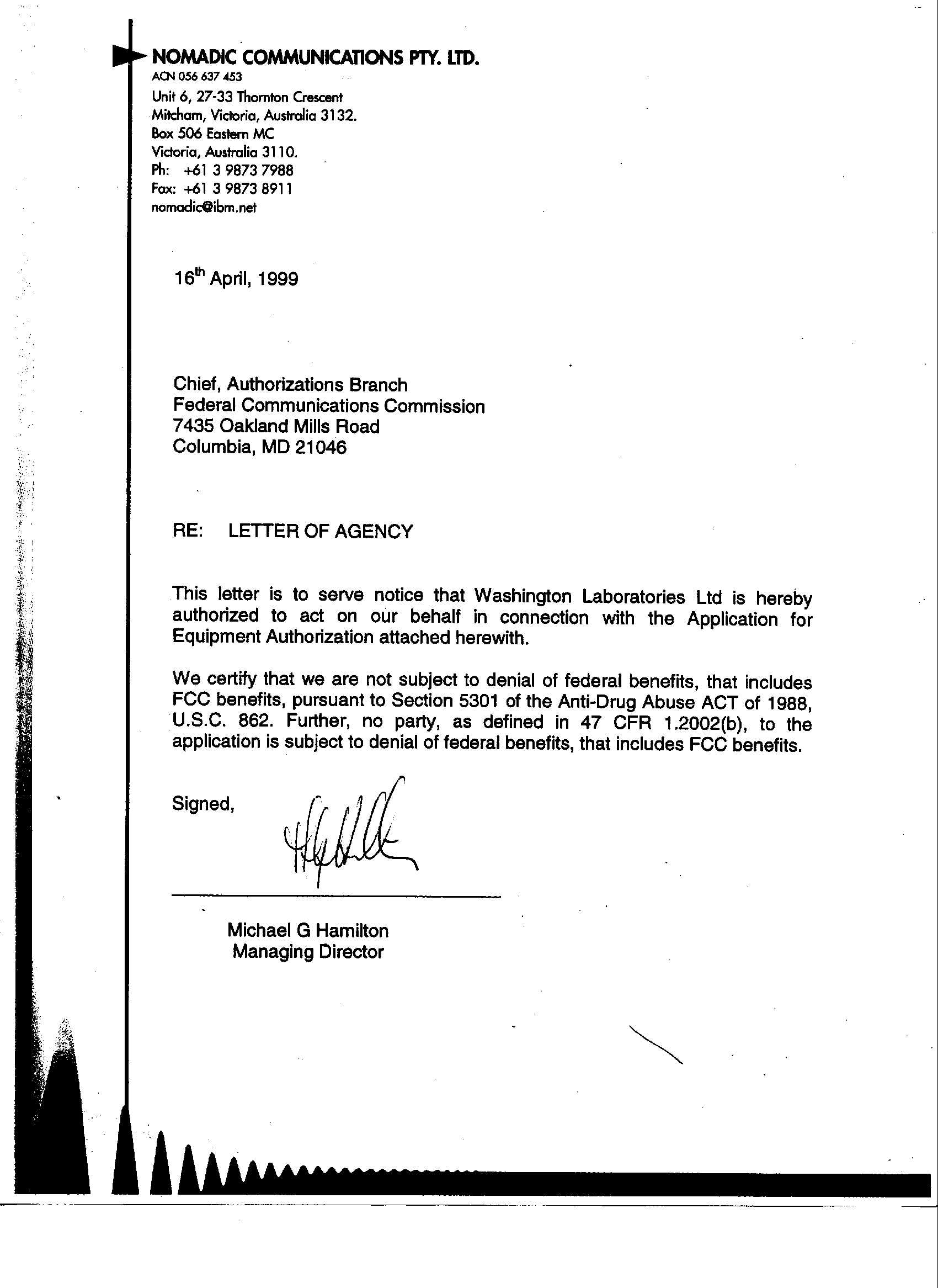
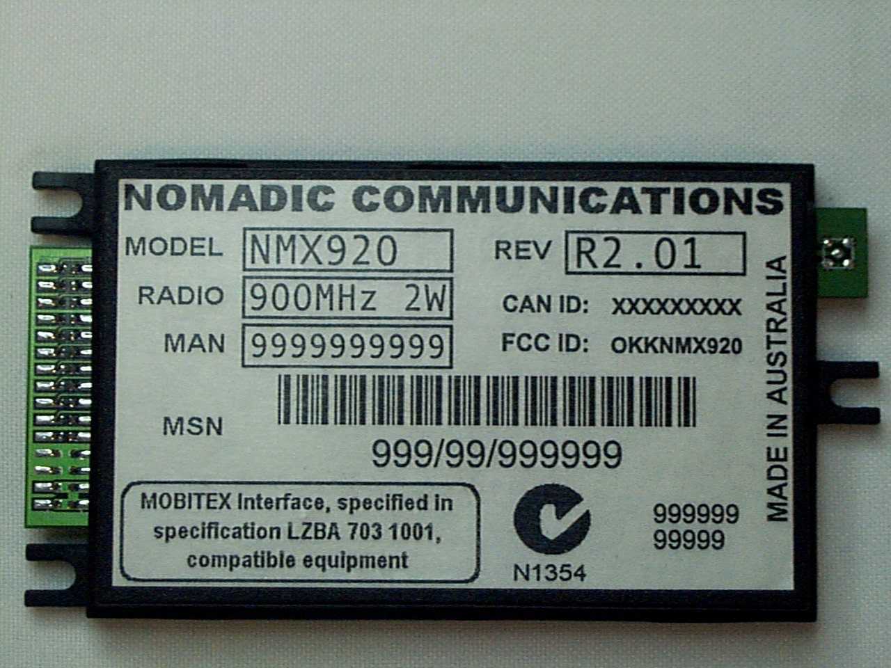
Nomadic Communications NMX920 Canada XXXXXXXX FCC ID:OKKNMX920
Operational Description
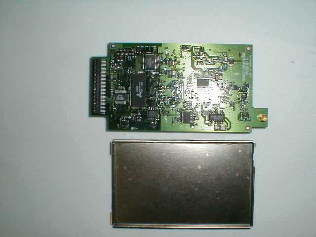
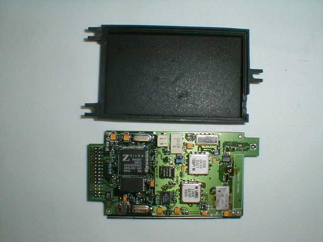
For further information consult the “OEM Designers Guide” available from Nomadic Communications NMX920 MOBITEX® RADIO MODEM TECHNICAL SPECIFICATION NOMADIC COMMUNICATIONS NMX920 MOBITEX® RADIO MODEM TECHNICAL SPECIFICATION November 1999. Overview The NMX920 is a 900MHz Mobitex® Radio Packet Modem designed for integration into third party OEM equipment. The NMX920 is a compact, single board design housed in an EMI shielded enclosure with MMCX antenna connector and single power and data connector. Integration of the NMX920 into existing and new designs is simplified by the use of a single 30 way Flexible Printed Circuit (FPC), Board to Board connector or cable for data, control and power signals. Key Features q Compatible with 900MHz Mobitex® networks in North America. q Low power consumption for prolonged battery life. q Flexible packaging configurations with optional connector styles and casing options. q Certified MIS conformance q 2 W nominal power transmitter for effective indoor and fringe area use. q High tolerance to EMI produced by close proximity electronics, or coupled through signalling interface. Approvals q Mobitex® compliant to MIS 4A, including R14N and WSM q FCC (Pending) q Industry Canada (Pending) For further information consult the “OEM Designers Guide” available from Nomadic Communications NMX920 MOBITEX® RADIO MODEM TECHNICAL SPECIFICATION Radio Transceiver Specification General Dual conversion receiver, directly modulated transmitter utilising common antenna and solid state transmit/receive RF switch. Modulation Technique NRZ GMSK (BT=0.3) Transmitter Frequency Range 895 – 905 MHz (800 channels) Receive Frequency Range 931 – 941 MHz (800 channels) Channel Spacing 12.5 kHz Frequency Accuracy ±1.2 kHz over full operating temperature range Receiver Sensitivity -116 dBm Transmitter Power (typical) 2 W @ 6.5 – 7.5 VDC into matched 50Ω antenna load at 20°C Transmitter Power Control 4 level transmit power control (0, -6dB, -12dB and –18dB) Antenna Cable Connector MMCX Female Environmental Specification Operating Temperature -10°C to +55°C Storage Temperature -35°C to +80°C Cooling Method Convection and thermal conduction of an enclosed environment Operating Humidity 5% to 95% non-condensing relative humidity at +50°C for at least 8 hours Physical Specification Overall dimensions 100 mm x 55mm x 12 mm (standard enclosure) including connectors and mounting lugs Weight 50 g including standard enclosure Mounting Method M2 Screws at 3 positions Housing High density metal impregnated plastic clamshell Grounding Continuous-edge pressure fit grounding from case to PCB Power Requirements Supply Voltage 6.5 – 7.5 VDC Supply Ripple Less than 35mV rms All modes – Transmitting high power 1400 mA (typical) @ 7.0 VDC into matched 50Ω antenna at 20°C Express Mode – Receiving 130 mA (typical) @ 7.0 VDC into matched 50Ω antenna at 20°C Battery Saving Mode – Receiving 85 mA (ave) (typical) @ 7.0 VDC into matched 50Ω antenna at 20°C Power-off Mode 250 uA (typical) @ 7.0 VDC Device Interface Connector 30-way 0.50 mm pitch FPC socket, or 2 x 15 x 2mm Board to Board Connector, or cable Data link protocol Mobitex® Asynchronous Communications Protocol (MASC1) Data port RS-232 or TTL (Manufacturing Option) Data rate 1200 – 9600bps Any and all specifications are subject to change by Nomadic Communications Pty Ltd without notice except to the appropriate spectrum management authorities. The information in this specification is deemed reliable at the time of printing. Nomadic Communications does not assume responsibility for any errors that may appear in this specification nor any omissions that may have occurred at the time of printing. Interested parties must therefore rely on their own enquires. Nomadic Communications does not assume liability arising from the application or use of any information contained in this document or the product referred to by this document. Mobitex® is a registered trademark of Telia AB, Sweden. NOMADIC COMMUNICATIONS Level 3, 26-28 Prospect Street Box Hill Victoria 3128 AUSTRALIA ph: +61 3 9843 2000 fax: +61 3 9843 2022 email: [email protected]
Operational Description
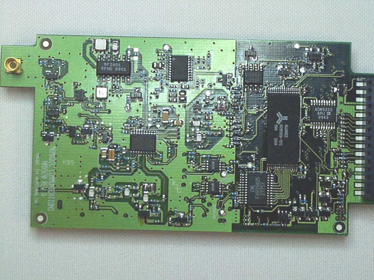
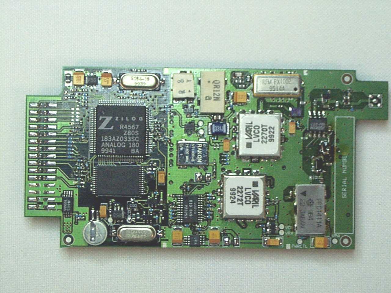
Operational Description Ci rc uit de scri pt io n. The channel frequency for both the transmitter and the receiver are controlled by two separate phase locked loops using a common VCTCXO reference of 14.40 MHz. The reference oscillator has a stability of +/-1ppm over the temperature range of –30 to +60 deg.C. There is circuitry that disables the transmitter whenever the PLL is out of lock. Maximum frequency error of the transmitter is +/-1.35KHz. Modulation is GMSK with a BT = 0.3. The gaussian filter associated with the modulator is contained inside the modem IC (U6, type FX909AD5). The modulation level is set by digitally controlled components that are adjusted only in manufacturing. Voice modulation is not possible. The resulting emission bandwidth complies with FCC 90.210 mask J. for any digital sequence. Data rate is fixed at 8.0KHz. The transmitter has a power leveling circuit to control the output power to within +/-2dB. There is no external control of the power output. The receiver uses dual conversion with a first IF of 86.85MHz injected on the high side of the carrier. There are no external filters associated with this product. Provision is made for the connection of an external antenna, required in normal operation. Function of semiconductor devices. This description is limited to the transceiver section of the unit only. Only semiconductor devices shown on sheets 6, 7, and 9 of the schematic diagram are detailed below. See the block diagram for the location of the devices identified by circuit reference numbers. VCO1Receiver voltage controlled oscillator used as part of the RX phase locked loop to generate the first mixer injection signal. First mixer injection is on the high side. VCO2Transmitter voltage controlled oscillator used as part of the TX phase locked loop. Runs a t the final TX freque nc y. XTL4Reference oscillator for both RX and TX phase locked loops. Runs at 14.4MHz. U16Phase comparators and frequency dividers. Part of both the RX and TX phase locked loops. Q6Second mi xer injectio n a mplifier operating a t 6 ti mes the reference freque nc y. U14RX front end amplifier and first mixer. U18RX first IF amplifier, second mixer, second IF amplifier, and demodulator. The first IF is 86.85MHz, the second IF is 450KHz and the second oscillator injection is on the low side. U23Level setting of the RSSI indicator from the receiver. U27TX pre-driver. Approximately 0dBm output. U15TX power amplifier driver. Approximately 6dBm output. U9TX final power amplifier with power control element. CU2RX/TX antenna changeover switch, driven by SQ2 and SQ3. D1TX forward power detector. Part of the TX power control loop. U17TX directional power coupler. Part of the TX power control loop. U10TX power control loop amplifier. Q4TX output disable. Used for ‘out of lock’ disable. U5TX modulation input amplifier. U28Digitally controlled components preset in manufacturing. U5RX demodulator buffer.
RF Exposure Info
RF Exposure The Nomadic NMX920 Radio Modem has been evaluated for compliance with RF Exposure requirements. SAR testing was performed by Aprel Laboratories with the following results: “The maximum Specific Absorption Rate (SAR) averaged over 1 g, determined at 901MHz (high channel), of the Nomadic Communications OEM radio modem, NMX920, is 1.41 W/kg when operating with an 9 % duty factor. The overall margin of uncertainty for this measurement is ± 16.2 % (Appendix C). The SAR limit given in the FCC 96-326 safety guideline is 1.6 W/kg. This unit as tested, and as it will be marketed, is found to be compliant with this requirement” The following 2 pages are taken from the Nomadic’s NMX920 OEM Integrators Guide. NMX920 OEM Integrators Guide Page 13 of 21 7. Notes for Integrators Application developers should be aware of the following hardware firmware and operational issues prior to commencement of integration of the NMX920. These issues impact hardware design, application software and application certification by the network operator. 7.1. Antenna The NMX920 requires a 50 Ω ΩΩ Ω= == =matched antenna with a VSWR no greater than 1.5:1 over the transmission band. The provision of the antenna system is the responsibility of the system integrator. The design and location of the antenna system will be largely dictated by system requirements, and may have system implications with respect to RF exposure, see regulatory issues below. During certification testing, the NMX920 was tested using a unity gain (dipole), ground independent antenna, and a printed circuit antenna of proprietary design. The unity gain (dipole), ground independent antenna used was manufactured by ZCG Scalar has the following characteristics, but these characteristics are common to both ground independent and ground referenced antennas from a number of manufacturers. Frequency 890 – 960 MHz Gain Unity, (0 dBd) Mounting Straight Connection TNC Power 5 Watts Impedance (Nom.) 50 Ohm Polarisation Vertical polarisation Construction Delrin, brass and steel Tuning Factory 7.2. Human Exposure Issues The NMX920 has been evaluated for human exposure to RF radiation under Specific Absorption Rate (SAR) guidelines by APREL Laboratories. The NMX920 was battery powered, and utilised the antenna detailed above. The NMX920 was run with development firmware which restricted the maximum transmit duty cycle to 9%. All production with firmware above R2.00 are limited to a maximum of 9% transmit duty cycle. This parameter is not alterable in the field. The configuration used for SAR testing was • •• •= == =NMX920, pre-production sample (DUT) • •• •= == =7.2 V Li-Ion battery pack • •• •= == =DYNMAST A-409T 800-900 MHz vertical handheld antenna (described above) The results of the SAR testing are summarised as “The maximum Specific Absorption Rate (SAR) averaged over 1 g, determined at 901MHz (high channel), of the Nomadic Communications OEM radio modem, NMX920, is 1.41 W/kg when operating with an 9 % duty factor. The overall margin NMX920 OEM Integrators Guide Page 14 of 21 of uncertainty for this measurement is ± 16.2 % (Appendix C). The SAR limit given in the FCC 96-326 safety guideline is 1.6 W/kg. This unit as tested, and as it will be marketed, is found to be compliant with this requirement” The complete SAR report is available on request from Nomadic Communications. If the final integration uses a different antenna configuration, the entire system will need to be re-evaluated for human exposure to RF radiation. Human exposure to RF radiation is a very complex system issue. It is affected by parameters (but not limited to) such as − −− −= == =Antenna − −− −= == =Power Supply − −− −= == =Application − −− −= == =Case − −− −= == =Accessories − −− −= == =Antenna placement. If the complete system is operated in a fixed location, mobile application or portable application with a unity gain (0 dBd) antenna and a guaranteed minimum separation of at least 20 cm between the antenna and any body then the NMX920 can be used in the system without further evaluation. If a higher gain antenna is used then Maximum Permissible Exposure guidelines must be checked, and application possibly made for change in licence conditions. If the NMX920 is to be used in a body worn application, or if a 20 cm separation between antenna and body cannot be guaranteed by obstruction, then the entire integrated system must be re-evaluated for SAR. SAR evaluation will need to be done for all available options for the final systems – all different battery packs, cases, antennas, power supplies, attached peripherals, after market accessories etc.
RF Exposure Info
Certification Report on Specific Absorption Rate (SAR) Experimental Analysis Nomadic Communications NMX 920 OEM Radio - Modem Date: 30 November, 1999 51 Spectrum Way Nepean ON K2R 1E6 Tel: (613) 820-2730 Fax: (613) 820-4161 email: [email protected] This report shall not be reproduced, except in full, without the express written approval of APREL Laboratories. Page 1 of 21© APREL Project #: NOMA-NMX920-3336 51 Spectrum WayTel. (613) 820-2730 Nepean, Ontario, K2R 1E6Fax (613) 820 4161 e-mail: [email protected] This report shall not be reproduced, except in full,without the express written approval of APREL Laboratories. CERTIFICATION REPORT Subject:Specific Absorption Rate (SAR) Experimental Analysis Product:OEM Radio-Modem Model:NMX 920 Client:Nomadic Communications Address:Level 3, 26-28 Prospect Street Box Hill, Victoria Australia, 3128 Project #:NOMA-NMX920-3336 Prepared by:APREL Laboratories 51 Spectrum Way Nepean, Ontario K2R 1E6 Tested by___________________________Date: ________________ Heike Wünschmann, C.E.T. Submitted by____________________________Date: _________________ Dr. Paul G. Cardinal Director, Laboratories Approved by_____________________________Date: _________________ Dr. Jacek J. Wojcik, P. Eng. Page 2 of 21© APREL Project #: NOMA-NMX920-3336 51 Spectrum WayTel. (613) 820-2730 Nepean, Ontario, K2R 1E6Fax (613) 820 4161 e-mail: [email protected] This report shall not be reproduced, except in full,without the express written approval of APREL Laboratories. FCC ID:OKKNMX920 Applicant:Nomadic Communications Equipment:OEM radio-modem Model:NMX 920 Standard:FCC 96 –326, Guidelines for Evaluating the Environmental Effects of Radio- Frequency Radiation ENGINEERING SUMMARY This report contains the results of the engineering evaluation performed on a Nomadic Communications OEM radio modem, NMX 920. The measurements were carried out in accordance with FCC 96-326. The OEM radio modem was evaluated for its maximum nominal power level of 2 W(33 dBm). The NMX 920 was tested at high, middle, and low frequencies, with the maximum SAR coinciding with the peak performance RF output power of the high channel (901 MHz) located on the antenna. Test data and graphs are presented in this report. Based on the test results, and as the device will be marketed and used (with the duty factor intrinsically limited to 9% or less – 32.4 seconds or less in any 6 minute time window), it is certified that the product meets the requirements as set forth in the FCC 96-326 requirement, for an uncontrolled RF exposure environment. Page 3 of 21© APREL Project #: NOMA-NMX920-3336 51 Spectrum WayTel. (613) 820-2730 Nepean, Ontario, K2R 1E6Fax (613) 820 4161 e-mail: [email protected] This report shall not be reproduced, except in full,without the express written approval of APREL Laboratories. TABLE OF CONTENTS 1.Introduction........................................................................................................................4 2.Applicable Documents.......................................................................................................4 3.Equipment Under Test.......................................................................................................4 4.Test Equipment..................................................................................................................5 5.Test Methodology..............................................................................................................5 6.Test Results........................................................................................................................6 6.1.Transmitter Characteristics........................................................................................6 6.2.SAR Measurements....................................................................................................7 7.Conclusions........................................................................................................................9 Appendix A..............................................................................................................................10 Appendix B..............................................................................................................................15 Appendix C..............................................................................................................................17 Appendix D..............................................................................................................................18 Appendix E...............................................................................................................................21 Page 4 of 21© APREL Project #: NOMA-NMX920-3336 51 Spectrum WayTel. (613) 820-2730 Nepean, Ontario, K2R 1E6Fax (613) 820 4161 e-mail: [email protected] This report shall not be reproduced, except in full,without the express written approval of APREL Laboratories. 1. INTRODUCTION Tests were conducted to determine the Specific Absorption Rate (SAR) of a sample of a Nomadic Communications OEM radio modem NMX 920. These tests were conducted at APREL Laboratories’ facility located at 51 Spectrum Way, Nepean, Ontario, Canada. A view of the SAR measurement setup can be seen in Appendix A Figure 1. This report describes the results obtained. 2. APPLICABLE DOCUMENTS The following documents are applicable to the work performed: 1) FCC 96-326, Guidelines for Evaluating the Environmental Effects of Radio- Frequency Radiation 2) ANSI/IEEE C95.1-1992, IEEE Standard for Safety Levels with Respect to Human Exposure to Radio Frequency Electromagnetic Fields, 3 kHz to 300 GHz. 3) ANSI/IEEE 95.3-1992, IEEE Recommended Practice for the Measurement of Potentially Hazardous Electromagnetic Fields – RF and Microwave. 4) OET Bulletin 65 (Edition 97-01) Supplement C (Edition 97-01), “Evaluating Compliance with FCC Guidelines for Human Exposure to Radio Frequency Electromagnetic Fields”. 3. EQUIPMENT UNDER TEST • Nomadi…
Text truncated - open the document above for the full version.
Test Report
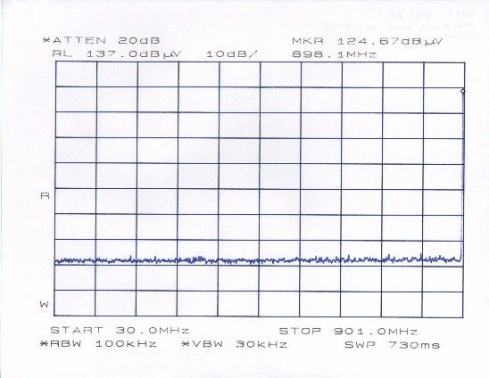
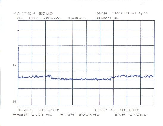
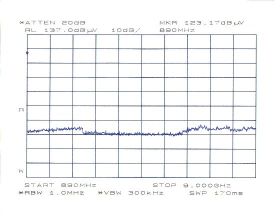
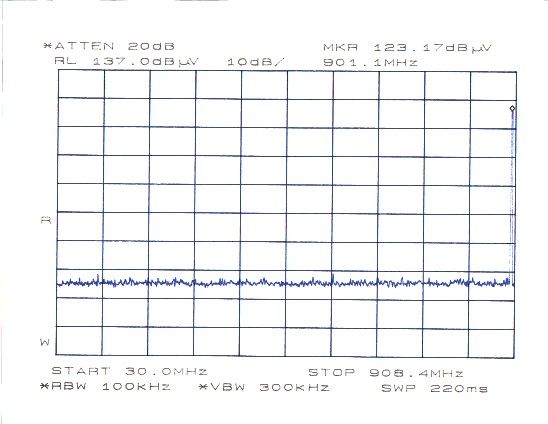
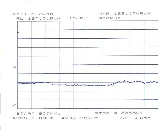
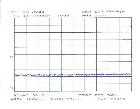
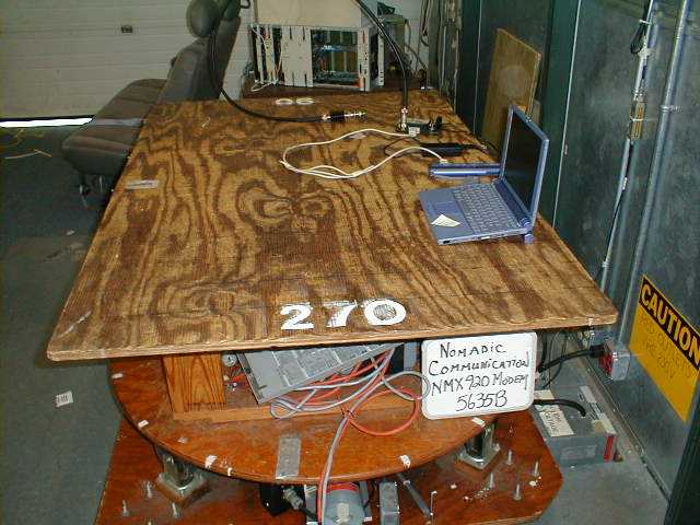
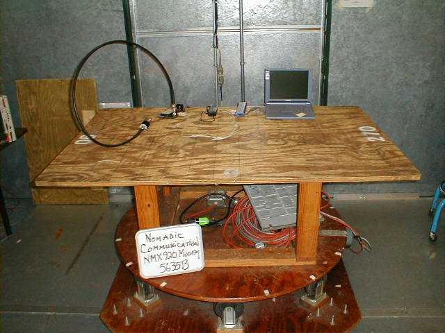
FCC CERTIFICATION TEST REPORT prepared for Nomadic Communications PTY Ltd. Level 3, 26-28 Prospect Street Box Hill, Victoria Australia 3128 FCC ID: OKKNMX920 February 14, 2000 WLL PROJECT #: 5633X This report shall not be reproduced, except in full, without the prior written consent of Washington Laboratories, Ltd. Nomadic Communications PTY Ltd. FCC ID: OKKNMX920 WLL Project #: 5633X i TABLE OF CONTENTS Statement of Qualifications ________________________________________________ 1.0 INTRODUCTION................................................................................................................................................... 1 1.1 S UMMARY .............................................................................................................................................................. 1 2.0 DESCRIPTION OF EQUIPMENT UNDER TEST (EUT).................................................................................. 2 3.0 TEST CONFIGURATION..................................................................................................................................... 2 3.1 RF O UTPUT P OWER (FCC R ULE P ART 2.1046) ...................................................................................................... 2 3.2 M ODULATION C HARACTERISTICS (FCC R ULE P ART 2.1047).................................................................................. 3 3.3 O CCUPIED B ANDWIDTH (FCC R ULE P ART 2.1049) ................................................................................................ 3 3.5 R ADIATED E MISSIONS T ESTIN G (FCC R ULE P ART 2.1053)..................................................................................... 4 3.5.1 Radiated Data Reduction and Reporting ...................................................................................................... 4 3.6 F REQUENCY S TABILITY (FCC R ULE P ART 2.1055) ................................................................................................. 6 3.6.1Frequency Stability for Voltage Variation............................................................................................ 7 3.6.2 Frequency Stability for Temperature Variation.................................................................................... 8 TABLES Table 1.Radiated Emissions Data Table 2.Measurement Equipment Used APPENDICES Appendix A.Occupied Bandwidth Plot Appendix B.Spurious Emissions at Antenna Terminals Plot Appendix C.Statement of Measurement Uncertainty Nomadic Communications PTY Ltd. FCC ID: OKKNMX920 WLL Project #: 5633X ii Nomadic Communications PTY Ltd. FCC ID: OKKNMX920 WLL Project #: 5633X 1 FCC CERTIFICATION REPORT for Nomadic Communications PTY Ltd. 1.0 Introduction This report has been prepared on behalf of Nomadic Communications PTY Ltd. in support of their application for FCC Certification under Part 90 of the FCC Rules and Regulations. The Equipment Under Test was the Mobitex RF Modem (Model NMX920). All measurements were performed at Washington Laboratories, Ltd. test center in Gaithersburg, MD. Site description and site attenuation data have been placed on file with the FCC's Sampling and Measurements Branch at the FCC laboratory in Columbia, MD. Washington Laboratories has been accepted by the FCC and approved by NIST NVLAP (NVLAP Lab Code 200066-0) as an independent FCC test laboratory. Measurements were made on the Equipment Under Test in accordance with FCC Rule Part 2, specifically the requirements stipulated in: 2.1046 RF Power Output 2.1047 Modulation Characteristics 2.1049 Occupied Bandwidth 2.1051 Spurious Emissions at Antenna Terminals 2.1053 Field Strength of Spurious Radiation 2.1055 Frequency Stability All results reported herein relate only to the item tested. This report shall not be used to claim product endorsement by NVLAP or any agency of the US Government. The measurement uncertainty of the data contained herein is ± 2.3 dB. Refer to Appendix C for Statement of Measurement Uncertainty. 1.1 Summary The Nomadic Communications PTY Ltd. Mobitex RF Modem complies with the technical requirements of Part 90 of the FCC Rules and Regulations. Nomadic Communications PTY Ltd. FCC ID: OKKNMX920 WLL Project #: 5633X 2 2.0 Description of Equipment Under Test (EUT) The Nomadic Communications PTY Ltd. Mobitex RF Modem is a 900MHz Mobitex radio packet modem designed for integration into third party (OEM) equipment. The EUT contains a MMCX Female antenna connector and power/data interface connector. The two watt radio uses GMSK modulation on 12.5kHz channels. The frequency range of operation is from 895 MHz to 905 MHz with up to 800 channels. Testing was performed at a low channel (896.0125 MHz), middle channel (898.375 MHz), and high channel (900.875 MHz). Frequency Range:895 MHz - 905 MHz Modulation:GMSK Number of Channels:800 Maximum Output Power:2.04 watts 3.0 Test Configuration 3.1 RF Output Power (FCC Rule Part 2.1046) Testing was performed on a low, middle and high transmit channel. Power to the EUT was supplied via a 7V AC/DC adapter through the interface board. During testing, the EUT was connected to a DK2 Modem Regulator and Interface Board via the modem cable. The RS-232 port of the DK2 was connected to the PC serial port for software control. Specific Nomadic software program (NMXTOOL.EXE) was used to program the test frequency, power level, modulation (on/off), transmit time, and transmit control (on/off). I/O PortsI/O Cables RS-232 Port/Modem Port2 meter shielded/foil, Modem to Interface Board RF Antenna Port2 ft., shielded/ braided, Modem to 50 Ω Load The output from the transmitter was connected to a 20dB attenuator and then to the input of an HP 8564E RF Spectrum Analyzer. The analyzer offset was adjusted to compensate for the 20dB attenuator. The RF output pow…
Text truncated - open the document above for the full version.
Contact Information
Applicant
Michael Hamilton(Managing Director)
Technical Contact
Washington Laboratories, Ltd.Gregory M Snyder
[email protected]301/417-0220
7560 Lindbergh Drive · Gaithersburg, Maryland · United States
Non-Technical Contact
Washington Laboratories, Ltd.Ann S Miller
[email protected]301/417-0220
Test Firm
Washington Laboratories, Ltd.Michael Violette
Technical Specifications
| # | Rule Parts | Frequency Range | Power Output | Emission | Tolerance |
|---|---|---|---|---|---|
| 1 | 90 | 895 MHz - 905 MHz | 2 W | 12K5F1D | 1.5000000000 ppm |
Other Applications from Nomadic Communications PTY Ltd.
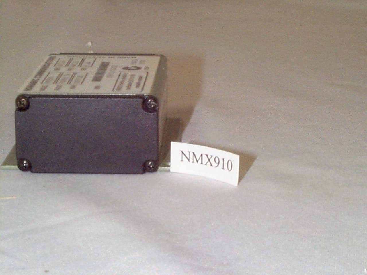
OKKNMX910
Oct 25, 1999Mobitex Transmitter Module
Equipment Class
TNB - Licensed Non-Broadcast Station Transmitter