OLDBDA800BIDIRECTIONAL AMPLIFIER
J. Randall Company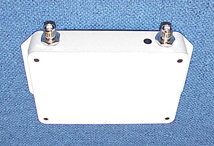
Click to zoom
Application Details
- Equipment Class
- AMP - Amplifier
- Date of Grant
- Sep 27, 1999
- Application Purpose
- Original Equipment
- Date of Application
- Jun 03, 1999
- Equipment Note
- BIDIRECTIONAL AMPLIFIER
- Frequency Range
- 851.00000000 - 869.00000000
- Company
- J. Randall Company
- Country
- United States
Documents & Files
Document Text
Text extracted from the exhibit documents filed with the FCC. Open a document above to read the original.
Users Manual
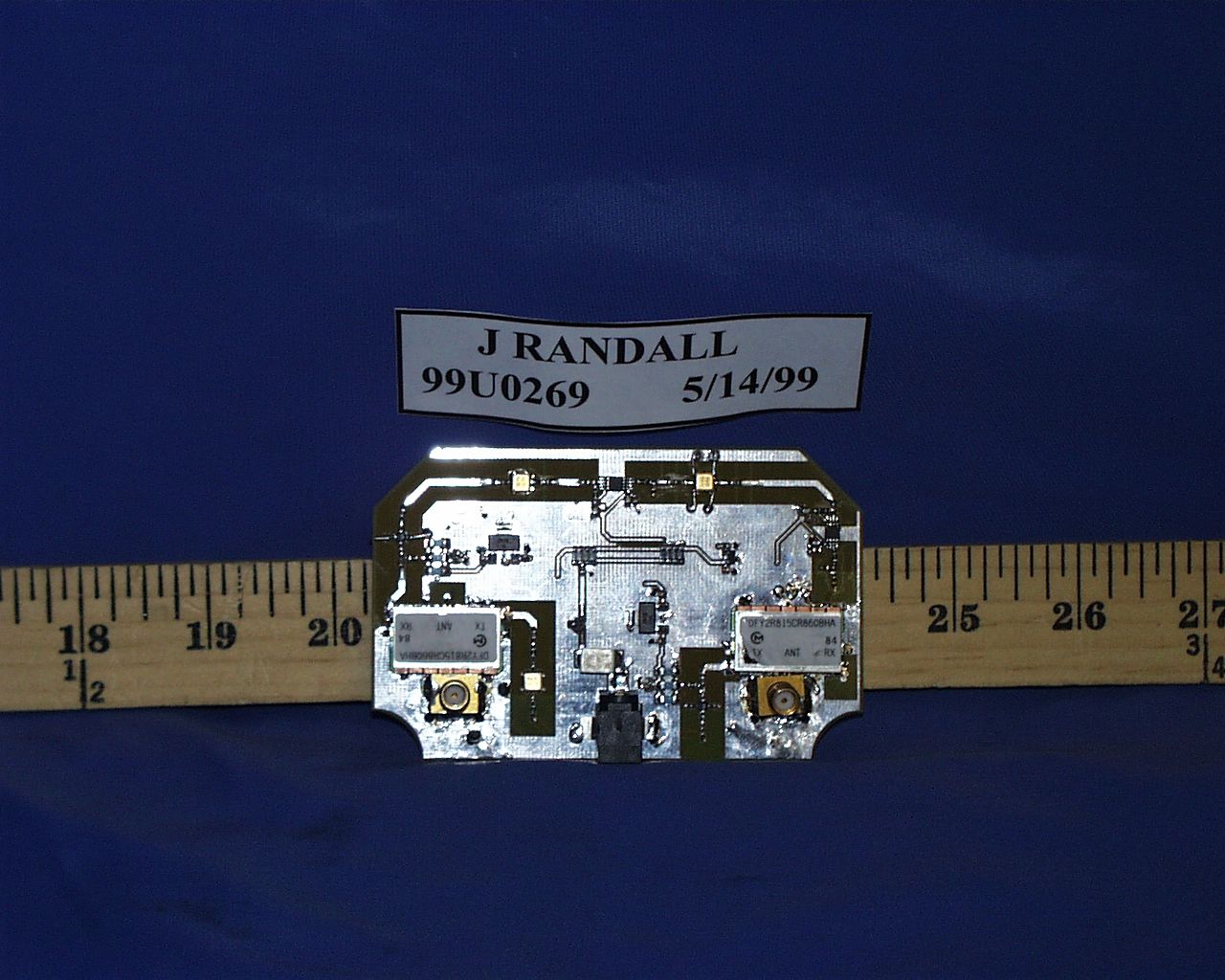
FUNCTIONAL DESCRIPTION Overview It is difficult to use portable cell phones and radios inside buildings due to the RF loss created by walls. By the time the basestation signal reaches the phone/radio inside the signal is too low to work. The BDA800 enhances portable and radio performance inside buildings. It amplifies the signal from the basestation and the signal from the portable/radio. The outside antenna receives the signal from the basestation. The signal is amplified and filtered by the BDA800. The inside antenna retransmits this signal. The inside antenna receives the signal from the mobile/radio. The BDA800 filters and amplifies this signal. The outside antenna then retransmits the signal. Installed Configuration In a typical configuration the BDA800 is connected to two antennas. The outside antenna is pointed at the basestation. The inside antenna is used to re-radiate the signal inside the building. The gain of the repeater can be configured for between 10dB and 45dB. The unit operates on signals from 806-824MHz for the Uplink and 851-869MHz for the Downlink. Up to 16 users can operate with the BDA. Circuit Description The BDA800 is power via a 110VAC to 12V wall transformer. It is available in several different package and input/output configurations. Plastic and metal boxes as well as TNC, BNC, and Type N connectors are readily available options The BDA800 receives the basestation signal from the outside antenna. The signal passes through a diplexer. It is then amplified and filtered. The amplifier will reduce its gain in order to prevent the signal power from increasing beyond the rated power levels. The signal passes through another diplexer that is used to keep the signal from affecting the other path. In the other direction the BDA800 receives the mobile/radio signal from the inside antenna. The signal passes through a diplexer. It is then amplified and filtered. The amplifier will reduce its gain in order to prevent the signal power from increasing beyond the rated power levels. The signal passes through another diplexer that is used to keep the signal from affecting the other path.
Users Manual
J. RANDALL COMPANY eAMP INSTALLATION MANUAL FOR SIGNAL BOOSTER Model BDA800 Table of Contents 1.0 Introduction 2.0 Installation 3.0 Troubleshooting 1.0 INTRODUCTION The eAMP provides amplification of signals in both the Uplink and Downlink direction. The purpose of the eAMP is to improve the signal quality inside buildings where the signal is weak. The eAMP is designed to be used only in confined or indoor areas such as buildings, tunnels, underground areas, etc., or remote areas, i.e., areas where there is little or no risk of interference to other users. The unit is permanently installed in a location that aids in producing the maximum benefit for the user while transmitting less power than a mobile. 2.0 INSTALLATION MANUAL FOR THE eAMP (Model BDA800) Proper fixed installation of the eAMP system is important to the operation of the system. Make sure you follow all the instructions provided. Also, follow the instructions provided by the manufacturers of the ancillary equipment such as the antennas, cables, etc. There are four steps to permanently installing the eAMP product. They are: 1) Locating and permanently installing the Inside Antenna 2) Locating and permanently installing the Outside Antenna 3) Cable it up and walk the area 4) Secure and protect Equipment You must follow these instructions to properly use the eAMP in a wireless system. Make sure you are qualified in the installation of equipment of this type. If not make sure you secure the services of a qualified expert. Potential RF Hazard Warning : While operating this device, radio frequency radiation exposure limits (47 CFR 1.1310) may be exceeded at distances closer than 20 centimeters (8 inches) from the device antenna (s). 1)Locating and Permanently installing the Inside Antenna With your phone in test mode walk the area that is suffering from poor coverage. Note weather the entire area needs to be improved or if there is an isolated area that suffers. You may only need to improve the room or area with poor coverage. This could make the installation much easier. Using this information make a note of the best location for placing the inside antenna. In addition to the safety issue the basic rule for placing the inside antenna is that walls are extremely bad for radio waves. An average wall can reduce the signal level by a factor of 10. Therefor two walls could reduce the radio signal to 1/100 of the original level. Make sure to locate the inside antenna in an effort to minimize the number of walls between the inside antenna and the desired coverage area. If it is necessary to use more than one inside antenna to properly cover the problem area then refer to the alternate installation diagrams. Figure 1 - Building with poor coverage 52' 6" x 20' 0" Poor Signal No Signal Weak Signal Weak Signal Possible Inside Antenna Location 2)Locating and Permanently installing the Outside Antenna With your phone in test mode measure the received signal strength (RSS) on the roof. Make sure you have a clear view of the basestation. Do not position the antenna in a location where obstructions block the signal path to the basestation. If you cannot receive a good signal on the roof it is unlikely that you will be able to improve the coverage inside the building. The outside antenna should point in the direction of the basestation and should be vertically polarized. The location of the outside antenna is based on several factors. Choose the location with: A) The greatest signal strength (biggest RSS). Use a mast as tall as allowed by the building owner and local codes. In most cases the higher the antenna is the stronger the signal will be. B) Easy access for the cable to enter the building. There are common areas that typically run cables inside and outside the building. Use this existing cable entry if possible. Venting ducts on the side of buildings are also good options. Try at not to add any holes in the roof. If you must make any structural modifications make sure you use a professional contractor. C) Try to minimize the length of the cable run. You have already determined where the inside antenna will go so you should have a good idea how long the cable will need to be. Figure 2 – Permanent Antenna Installation 53' 0" x 12' 6" Attic or drop ceiling Cable Access Outside Antenna Inside Antenna 3) Cable it up and walk the area Pull the RF cable from the outside antenna to the eAMP. Connect the eAMP to the inside antenna. Plug the eAMP into a standard electrical outlet. With your phone in test mode walk the area that was suffering from poor coverage and note the difference in coverage. If everything is satisfactory then proceed to the last step. If you are not satisfied go to the trouble shooting section. Figure 3 - Building with good coverage after eAMP installation 4)Permanently Secure and Protect all of the Equipment Follow all of the equipment manufacturers instructions for permanent installation. A) Install a lightning suppressor on the cable to the outside antenna if desired. The eAMP is not protected or warranted against lightning strikes. If the area is known for stormy weather it is advisable to protect the eAMP. This includes using proper grounding of the outside antenna and mast. B) Waterproof all connections that are exposed to the elements. C) Permanently secure all the eAMP, antennas, mast and cables. Use guide wires to secure the mast if necessary. 52' 6" x 20' 0" Good Signal Good Signal Good Signal Good Signal Possible Inside Antenna Location Other considerations 1) Standard Installation It is usually best to install the eAMP close to the inside antenna. See the illustration below Figure 4 Standard eAMP Installation eAMP Long Cable Run Inside Antenna 3.0Trouble Shooting Problem 1 - No difference in quality after system is installed S1Check to see if unit is plugged in. Make sure the unit is not plugged into outlet that is switched off. S2Check all RF connections S3Are both antennas installed S4The RF cable is not rated for…
Text truncated - open the document above for the full version.
Users Manual
J. RANDALL COMPANY eAMP INSTALLATION MANUAL FOR SIGNAL BOOSTER Model BDA800 Table of Contents 1.0 Introduction 2.0 Installation 3.0 Troubleshooting 1.0 INTRODUCTION The eAMP provides amplification of signals in both the Uplink and Downlink direction. The purpose of the eAMP is to improve the signal quality inside buildings where the signal is weak. The eAMP is designed to be used only in confined or indoor areas such as buildings, tunnels, underground areas, etc., or remote areas, i.e., areas where there is little or no risk of interference to other users. The unit is permanently installed in a location that aids in producing the maximum benefit for the user while transmitting less power than a mobile. 2.0 INSTALLATION MANUAL FOR THE eAMP (Model BDA800) Proper fixed installation of the eAMP system is important to the operation of the system. Make sure you follow all the instructions provided. Also, follow the instructions provided by the manufacturers of the ancillary equipment such as the antennas, cables, etc. There are four steps to permanently installing the eAMP product. They are: 1) Locating and permanently installing the Inside Antenna 2) Locating and permanently installing the Outside Antenna 3) Cable it up and walk the area 4) Secure and protect Equipment You must follow these instructions to properly use the eAMP in a wireless system. Make sure you are qualified in the installation of equipment of this type. If not make sure you secure the services of a qualified expert. Potential RF Hazard Warning : While operating this device, radio frequency radiation exposure limits (47 CFR 1.1310) may be exceeded at distances closer than 20 centimeters (8 inches) from the device antenna (s). 1)Locating and Permanently installing the Inside Antenna With your phone in test mode walk the area that is suffering from poor coverage. Note weather the entire area needs to be improved or if there is an isolated area that suffers. You may only need to improve the room or area with poor coverage. This could make the installation much easier. Using this information make a note of the best location for placing the inside antenna. In addition to the safety issue the basic rule for placing the inside antenna is that walls are extremely bad for radio waves. An average wall can reduce the signal level by a factor of 10. Therefor two walls could reduce the radio signal to 1/100 of the original level. Make sure to locate the inside antenna in an effort to minimize the number of walls between the inside antenna and the desired coverage area. If it is necessary to use more than one inside antenna to properly cover the problem area then refer to the alternate installation diagrams. Figure 1 - Building with poor coverage 52' 6" x 20' 0" Poor Signal No Signal Weak Signal Weak Signal Possible Inside Antenna Location 2)Locating and Permanently installing the Outside Antenna With your phone in test mode measure the received signal strength (RSS) on the roof. Make sure you have a clear view of the basestation. Do not position the antenna in a location where obstructions block the signal path to the basestation. If you cannot receive a good signal on the roof it is unlikely that you will be able to improve the coverage inside the building. The outside antenna should point in the direction of the basestation and should be vertically polarized. The location of the outside antenna is based on several factors. Choose the location with: A) The greatest signal strength (biggest RSS). Use a mast as tall as allowed by the building owner and local codes. In most cases the higher the antenna is the stronger the signal will be. B) Easy access for the cable to enter the building. There are common areas that typically run cables inside and outside the building. Use this existing cable entry if possible. Venting ducts on the side of buildings are also good options. Try at not to add any holes in the roof. If you must make any structural modifications make sure you use a professional contractor. C) Try to minimize the length of the cable run. You have already determined where the inside antenna will go so you should have a good idea how long the cable will need to be. Figure 2 – Permanent Antenna Installation 53' 0" x 12' 6" Attic or drop ceiling Cable Access Outside Antenna Inside Antenna 3) Cable it up and walk the area Pull the RF cable from the outside antenna to the eAMP. Connect the eAMP to the inside antenna. Plug the eAMP into a standard electrical outlet. With your phone in test mode walk the area that was suffering from poor coverage and note the difference in coverage. If everything is satisfactory then proceed to the last step. If you are not satisfied go to the trouble shooting section. Figure 3 - Building with good coverage after eAMP installation 4)Permanently Secure and Protect all of the Equipment Follow all of the equipment manufacturers instructions for permanent installation. A) Install a lightning suppressor on the cable to the outside antenna if desired. The eAMP is not protected or warranted against lightning strikes. If the area is known for stormy weather it is advisable to protect the eAMP. This includes using proper grounding of the outside antenna and mast. B) Waterproof all connections that are exposed to the elements. C) Permanently secure all the eAMP, antennas, mast and cables. Use guide wires to secure the mast if necessary. 52' 6" x 20' 0" Good Signal Good Signal Good Signal Good Signal Possible Inside Antenna Location Other considerations 1) Standard Installation It is usually best to install the eAMP close to the inside antenna. See the illustration below Figure 4 Standard eAMP Installation eAMP Long Cable Run Inside Antenna 3.0Trouble Shooting Problem 1 - No difference in quality after system is installed S1Check to see if unit is plugged in. Make sure the unit is not plugged into outlet that is switched off. S2Check all RF connections S3Are both antennas installed S4The RF cable is not rated for…
Text truncated - open the document above for the full version.
ID Label/Location Info
PROPOSED FCC ID LABEL FORMAT AND LOCATION APPLICANT:J RANDALL CO. MODEL NO:BDA800 FCC ID:OLDBDA800 FCC ID:OLDBDA800 This device complies with part 15 of the FCC Rules. Operation is subject to the following two conditions: (1) This device may not cause harmful interference, and (2) this device must accept any interference received, including interference that may cause undesired operation. J RANDALL CO.MODEL NO::BDA800
RF Exposure Info
JRANDALL CO BI DIRECTIONAL AMP BDA800 Section 1.310 Population/Uncontrolled Exposure (300 - 1500 MHz) OUTDOOR UPLINKTX frequency (MHz) mW/cm^^2 Antenna from dBi to (G) numeric dBi 81 5 0.5433333 19.95262315 1 3 E (V/m) P = E^2 / 3770 45.258885 Tx Maximum Power Output Watts 0.0 5 sqrt(30 * P * G) Distance D = E 0.0975694 (meters) MP E 0.0975694 INDOOR DOWNLINKTX frequency (MHz) mW/cm^^2 Antenna from dBi to (G) numeric dBi 86 0 0.5733333 19.95262315 1 3 E (V/m) P = E^2 / 3770 46.491576 Tx Maximum Power Output Watts 0.0 2 sqrt(30 * P * G) Distance D = E 0.0600721 (meters) MP E 0.0600721
RF Exposure Info
JRANDALL CO BI DIRECTIONAL AMP BDA800 Section 1.310 Population/Uncontrolled Exposure (300 - 1500 MHz) OUTDOOR UPLINKTX frequency (MHz) mW/cm^^2 Antenna from dBi to (G) numeric dBi 81 5 0.5433333 19.95262315 1 3 E (V/m) P = E^2 / 3770 45.258885 Tx Maximum Power Output Watts 0.0 5 sqrt(30 * P * G) Distance D = E 0.0975694 (meters) MP E 0.0975694 INDOOR DOWNLINKTX frequency (MHz) mW/cm^^2 Antenna from dBi to (G) numeric dBi 86 0 0.5733333 19.95262315 1 3 E (V/m) P = E^2 / 3770 46.491576 Tx Maximum Power Output Watts 0.0 2 sqrt(30 * P * G) Distance D = E 0.0600721 (meters) MP E 0.0600721
Test Report
FCC CFR47 PART 90 PRIVATE LAND MOBIL RADIO SERVICES TEST REPORT FOR BIDIRECTIONAL AMPLIFIER MODEL: BDA800 FCC ID: OLDBDA800 REPORT NUMBER: 99U0269 ISSUE DATE:06/02/1999 , Prepared for J RANDALL CO. 1853 NORTH BISSELL 1 ST FLOOR CHICAGO, IL 60614-5012 Prepared by COMPLIANCE ENGINEERING SERVICES, INC. 1366 BORDEAUX DRIVE SUNNYVALE, CA 94089, USA TEL: (408) 752-8166 FAX: (408) 752-8168 REPORT NO:99U0269 ISSUE DATE:06/02/1999 BIDIRECTIONAL AMPLIFIER BDA800 TABLE OF CONTENTS PAGE 1.FCC PART 2, SUBPART J INFORMATION..........................................................................................................1 2.PRODUCT DESCRIPTION............................................................................................................................................4 3.TEST FACILITY................................................................................................................................................................4 4.ACCREDITATION AND LISTING..............................................................................................................................4 5.MEASUREMENT INSTRUMENTATION.................................................................................................................4 6.MEASURING INSTRUMENT CALIBRATION......................................................................................................5 7.UNITS OF MEASUREMENT.........................................................................................................................................5 8.CLASSIFICATION OF DIGITAL DEVICE..............................................................................................................5 9.RADIATED EMISSION LIMITS..................................................................................................................................6 10. RADIATED EMISSION TEST PROCEDURE..............................................................................................................6 11.AMBIENT CONDITIONS...............................................................................................................................................7 12.TEST EQUIPMENT LIST...............................................................................................................................................7 13.EUT SETUP PHOTOS......................................................................................................................................................8 14.TEST RESULT SUMMARY..........................................................................................................................................11 SECTION 2.985 RF POWER OUTPUT..............................................................................................................................13 SECTION 2.987 MODULATION CHARACTERISTICS...............................................................................................13 SECTION 2.989 OCCUPIED BANDWIDTH......................................................................................................................13 SECTION 2.991 SPURIOUS EMISSION AT ANTENNA TERMINALS..................................................................13 SECTION 2.993 FIELD STRENGTH OF SPURIOUS RADIATION.........................................................................18 SECTION 2.995 FREQUENCY STABILITY......................................................................................................................20 15.EXTERNAL I/O CABLE CONSTRUCTION DESCRIPTION..........................................................................20 EXHIBITS 1. AUTHORIZATION LETTER 2. PROPOSED FCC ID LABEL FORMAT 3. REQUEST FOR CONFIDENTIALITY LETTER 4. FUNCTIONAL DESCRIPTION 5. USER’S MANUAL 6. SCHEMATIC DIAGRAM 7. BLOCK DIAGRAM REPORT NO:99U0269 ISSUE DATE:06/02/1999 BIDIRECTIONAL AMPLIFIER BDA800 1 COMPLIANCE CONSULTING SERVICESDOCUMENT NO:CCSUP4031A 1366 BORDEAUX DRIVE SUNNYVALE, CA 94089 USA TEL:(408) 752-8166 FAX:(408) 752-8168 This report shall not be reproduced except in full, without the written approval of CCS. 1.FCC PART 2, SUBPART J INFORMATION FCC Rule 2.983 2.983 (a) Name of Applicant: J RANDALL CO. 1853 NORTH BISSELL 1 ST FLOOR CHICAGO, IL 60614-5012 Contact Person:PETE SPEVACEK / OPERATIONS MANAGER Telephone No:(877) 572-8328 2.983 (b)Equipment Identification:Refer to Exhibit 2. FCC ID:OLDBDA800 2.983 (c)Planned for quantity production. 2.983 (d)Technical description: The BDA800 enhances portable and radio performance inside buildings. It amplifies the signal from the basestation and the signal from the portable/radio. The outside antenna receives the signal from the basestation. The signal is amplified and filtered by the BDA800. The inside antenna retransmits this signal. The inside antenna receives the signal from the mobile/radio. The BDA800 filters and amplifies this signal. The outside antenna then retransmits the signal. Subsections (1) Types of Emissions: EXPANDR (2) Frequency Range: Uplink:806-824MHz Downlink:851-869MHz (3) Range of Operating Power: 10 – 45dB gain (-30dBm/+15dBm) Maximum Power Rating: Uplink14dBm (multi carrier) 17dBm (single carrier) Downlink10dBm (multi carrier) 13dBm (single carrier REPORT NO:99U0269 ISSUE DATE:06/02/1999 BIDIRECTIONAL AMPLIFIER BDA800 2 COMPLIANCE CONSULTING SERVICESDOCUMENT NO:CCSUP4031A 1366 BORDEAUX DRIVE SUNNYVALE, CA 94089 USA TEL:(408) 752-8166 FAX:(408) 752-8168 This report shall not be reproduced except in full, without the written approval of CCS. (4) Applied voltages and currents into the final transistor elements: 4.8 VDC at 0.065 A on U5 and U6 (5) Function of Each Active Device: Refer to Exhibit 6, Schematic Diagram. Confidentiality is requested on this item. (6) Complete Circuit Diagrams and Functional Diagram Refer to Exhibit 6 , Schematic Diagram. Confidentiality is requested on this item. (7) Instructions/Installation Manual Refer to Exhibit 4, User;s Manual (8) Tune-up/Op…
Text truncated - open the document above for the full version.
Contact Information
Applicant
Pete Spevacek(Operations Manager)
877-572-8328
Technical Contact
COMPLIANCE ENGINEERING SERVICES, INC.MIKE KUO
[email protected]408-752-8166
1366 BORDEAUX DRIVE · SUNNYVALE, California · United States
Non-Technical Contact
COMPLIANCE ENGINEERING SERVICES, INC.MIKE KUO
[email protected]408-752-8166
Test Firm
Compliance Certification Services IncSteve Cheng
Technical Specifications
| # | Rule Parts | Frequency Range | Power Output | Emission |
|---|---|---|---|---|
| 2 | 9 | 851 MHz - 869 MHz | 11.20 mW | EXTENDR |