OMBETM-FA-T-4FARM ALERT
ETM Industries Inc
Click to zoom
Application Details
- Equipment Class
- DXT - Part 15 Low Power Transceiver, Rx Verified
- Date of Grant
- Aug 25, 1999
- Application Purpose
- Original Equipment
- Date of Application
- Jul 05, 1999
- Equipment Note
- FARM ALERT
- Frequency Range
- 318.00000000 - 318.00000000
- Company
- ETM Industries Inc
- Country
- Canada
Documents & Files
Document Text
Text extracted from the exhibit documents filed with the FCC. Open a document above to read the original.
Users Manual
USER GUIDE Transformix Engineering Inc. 50 Grant Timmins Dr, Unit 3 Kingston, Ont. K7L 4V4 E.T.M IndustriesUser Guide Transformix Engineering Inc.i TABLE OF CONTENTS GENERAL DESCRIPTION: .......................................................................................................................... 1 SIGNAL LIGHT OPERATIONS: .................................................................................................................. 1 REPLACEABLE COMPONENTS: ............................................................................................................... 4 Taillight LED board:.................................................................................................................................. 4 Taillight Computer/Battery Module:.......................................................................................................... 5 Keypad unit:................................................................................................................................................ 7 TAILLIGHT/KEYPAD BATTERY REPLACEMENT: ................................................................................ 8 Taillight unit battery replacement: ............................................................................................................. 8 Keypad unit battery replacement: .............................................................................................................. 9 ELECTRICAL SPECIFICATIONS:............................................................................................................. 10 Keypad unit:.............................................................................................................................................. 10 Taillight unit: ............................................................................................................................................ 10 MECHANICAL SPECIFICATIONS: .......................................................................................................... 11 Keypad unit:.............................................................................................................................................. 11 Taillight unit: ............................................................................................................................................ 11 E.T.M IndustriesUser Guide Transformix Engineering Inc.1 GENERAL DESCRIPTION: The FARM ALERT system provides a farmer with a wireless lighting system for use on agricultural implements. This wireless system allows the user to control the turn signals, hazard lights, brake lights, and running lights all from a keypad unit located near the driver. Each signal is simply activated by pressing the corresponding key on the keypad. Lights on the keypad unit will indicate that a signal has been sent and received. These lights will continue to operate until a signal is sent to cancel the operation by simply pressing the same corresponding button on the keypad unit. SIGNAL LIGHT OPERATIONS: Sufficient LED lighting is used to ensure running light visibility at 150 meters on a clear night. Signal TypeResult Left Turn: Left Side, Bright, Flashing Right Turn: Right Side, Bright, Flashing Brake Lights: Left and Right Side, Bright Hazard Lights: Left and Right Side, Bright, Flashing Running Lights: Left and Right Side, Dim Bright - All LEDs on Dim - Half of the LEDs on E.T.M IndustriesUser Guide Transformix Engineering Inc.2 KEYPAD OVERVIEW: Note: The selected function will continue to operate until a signal is sent to cancel the function by simply pressing the same corresponding button. Right button: By pressing the RIGHT button on the keypad a signal is sent to the taillight unit to activate the right turning lights, a red confirmation light located above the button will let the user know that the signal was sent and received by the keypad unit. Left button: By pressing the LEFT button on the keypad a signal is sent to the taillight unit to activate the left turning lights. Brake button: By pressing the BRAKE button on the keypad a signal is sent to the taillight unit to activate the brake lights. The brake lights will continue to operate until a signal is sent to cancel the operation by simply pressing the same corresponding button. Running button: By pressing the RUNNING button on the keypad a signal is sent to the taillight unit to activate the running lights. E.T.M IndustriesUser Guide Transformix Engineering Inc.3 Hazard button: By pressing the HAZARD button on the keypad a signal is sent to the taillight unit to activate the hazard lights. Both lights above the RIGHT and the LEFT buttons will flash as a confirmation that hazard has been selected. Low battery keypad/taillight: A warning light will activate if the battery level for the keypad or the taillight drops below a certain level letting the user know that the batteries will have to be changed. E.T.M IndustriesUser Guide Transformix Engineering Inc.4 REPLACEABLE COMPONENTS: The replaceable components that make up the electrical hardware are: 1. Taillight LED board 2. Taillight Computer/Battery Module 3. Keypad unit Taillight LED board: The taillight lens module consists of a red molded lens cap, three screws and a LED circuit board. If the LED circuit board needs to be replaced, a new board can be easily installed. LED board removal To remove an LED board: 1) Remove the three lens screws from the red lens cap and then remove the lens cap. 2) Remove the two screws securing to the LED board. 3) Remove the LED board by pulling up on the LED board so that it disconnects from the connector located just underneath the board. LED board replacement To replace an LED board: 1) Take the new replacement LED board and by pushing down fit the board into the connector insuring that the connector is in the correct position. 2) Reinstall the two LED board screws. 3) Then place the red lens cap back over the main housing and rein…
Text truncated - open the document above for the full version.
ID Label/Location Info
LABEL REQUIREMENTS RF IC & FCC ETM Industries Inc.Model NO.:ETM-FA-T-4 CANADAFCC ID: OMBETM-FA-K-4 This device complies with Part 15 of the FCC Rules Operation is subject to the following two rules: (1) This device may not cause harmful interference, and (2) This device must accept any interference received, including interference that may cause undesired operation. Made in CANADA Label Dimensions: Length = 3” x Height = 2” LABEL FORMAT AND LOCATION Note: Label location appears on the backside of the unit.
ID Label/Location Info
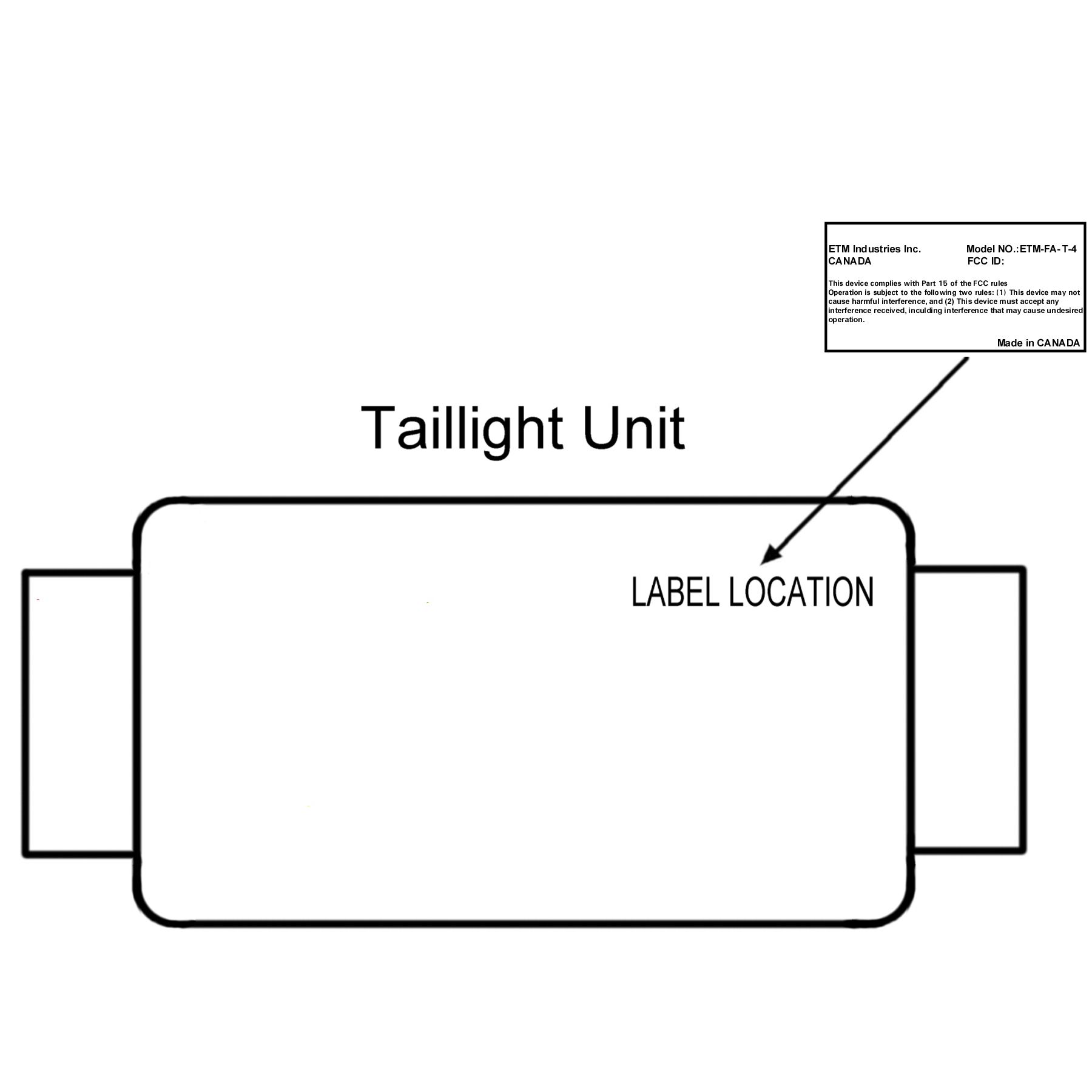
LABEL REQUIREMENTS RF IC & FCC ETM Industries Inc.Model NO.:ETM-FA-T-4 CANADAFCC ID: OMBETM-FA-T-4 This device complies with Part 15 of the FCC Rules Operation is subject to the following two rules: (1) This device may not cause harmful interference, and (2) This device must accept any interference received, including interference that may cause undesired operation. Made in CANADA Label Dimensions: Length = 3” x Height = 2” LABEL FORMAT AND LOCATION Note: Label location appears on the backside of the unit.
Operational Description
Technical Description of Unit DESCRIPTION: The Farm Alert’s function is to provide the farmer with a wireless lighting system for use on agricultural implements. The Farm Alert system consists of two separate units, the keypad unit, and the taillight unit. The keypad unit sends RF signals to the taillight unit and the taillight unit in turn sends a signal back as a confirmation that the signal was received. Pressing a selected button on the keypad unit will activate each signal. Lights on the keypad unit will indicate that a function has been sent and received. The signal lights on the taillight unit will continue to operate until the function is canceled by selecting the same corresponding button. The keypad unit can operate up to 100 feet away from the taillight unit. The Farm Alert system is powered by 4 standard “D” size and one 9V batteries that are easily obtained at any convenience store. The battery life is approximately 200 hours of normal operation at 25° C with alkaline batteries. There are two low battery warning light’s located on the keypad unit that will indicate a low battery condition for both the keypad unit and the taillight unit. Each unit is designed to withstand a temperature range between -20° C and +50° C. The keypad unit and the taillight units are both designed to withstand impact and vibration loading and to protect the electronic components from wind, water and dust. MECHANICAL SPECIFICATIONS: The mechanical system is made up of 2 assembled parts. One part is a hand held keypad unit that can be mounted in the cab of the vehicle. The second is a taillight unit that can be mounted on the rear of the implement under tow. Both units are designed to withstand impact and vibration loading and will protect the electronic components from the elements. Keypad unit: Temperature range: -20° to +50° Height: 3.1” Width: 7.3” Weight: 250g Taillight unit: Temperature range: -20° to +50° Height: 4.3” Width: 72” Weight: 1950g ELECTRICAL SPECIFICATIONS: Keypad unit: RF Range: 100 Ft Battery type: One 9 volt Battery life: Approximately 200 hours of normal operation at 25° C with alkaline (under use) batteries. Taillight unit: RF Range: 100 Ft Battery type: Four D cell’s Battery life: Approximately 200 hours of normal operation at 25° C with alkaline (under use) batteries. A low-battery detector is built into the keypad/taillight system. There are lights on the keypad unit to indicate a low battery condition for both the keypad unit and the taillight unit. Each unit is designed to withstand a temperature range between -20° C and +50° C. Both the keypad unit and the taillight unit are also designed to withstand impact, vibration and to protect the electronic components from the elements such as wind, water and dust.
Parts List/Tune Up Info
Transformix Engineering Inc. ETM PARTS LIST Item QtyPart NumberReference DesignatorDescriptionManufacturer / Supplier 12 SA626DU1RF Receiver, limiter/descriminatorPhillips / Avnet (Motorola) 26 BFR92LT1Q1, Q2,Q3RF Transistor, NPN, SOT 23 pkg.Motorola / Newark 32 BAR63 OR MMBV3700D1RF Diode, SOT-23 pkg.Siemans / Avnet 34 BAS21DICT-NDD2, D3Diode, SOT-23 pkgDigikey 42 RF1238S1318 MHz SAW Filter, TO-39 Case, 500 kHz BWRFM / Insight / Kaytronics 42 RO2118AY1318 MHz SAW resonator, +/- 80 kHz SM-2 CaseRFM / Insight / Kaytronics 52 RO2123AY2307.3 MHz SAW resonator, +/- 80 kHz SM-2 CaseRFM / Insight / Kaytronics 52 ANT-418-PW-QWANT1418 MHz AntennaLinx 64 PCC020CNCT-NDC9,C322 pF, +/- 0.25 pF, NPO dielectric, 50 V, "0805"Panasonic / Digikey 64 PCC030CNCT-NDC3, C133 pF, +/- 0.25 pF, NPO dielectric, 50 V, "0805"Panasonic / Digikey 74 PCC040CNCT-NDC8, C314 pF, +/- 0.25 pF, NPO dielectric, 50 V, "0805"Panasonic / Digikey 72 PCC050CNCT-NDC205 pF, +/- 0.25 pF, NPO dielectric, 50 V, "0805"Panasonic / Digikey 82 PCC060CNCT-NDC196 pF, +/- 0.25 pF, NPO dielectric, 50 V, "0805"Panasonic / Digikey 84 PCC070CNCT-NDC1, C57 pF, +/- 0.25 pF, NPO dielectric, 50 V, "0805"Panasonic / Digikey 92 PCC100CNCT-NDC1710 pF, 5%, NPO dielectric, 50 V, "0805"Panasonic / Digikey 92 PCC120CNCT-NDC2112 pF, 5%, NPO dielectric, 50 V, "0805"Panasonic / Digikey 102 PCC330CGCT-NDC433 pF, 5%, NPO dielectric, 50 V, "0805"Panasonic / Digikey 102 PCC390CGCT-NDC2839 pF, 5%, NPO dielectric, 50 V, "0805"Panasonic / Digikey 114 PCC101CGCT-NDC35, C40100 pF, 10%, NPO dielectric, 50 V, "0805"Panasonic / Digikey 112 PCC221CGCT-NDC51220 pF, +/- 5%, COG dielectric, 50 V, "0805"Panasonic / Digikey 122 PCC471BNCT-NDC7470 pF, +/- 10%, X7R dielectric, 50 V, "0805"Panasonic / Digikey 1216 PCC102CGCT-NDC2, C10, C11, 1000 pF, +/- 10%, NPO dielectric, 50 V, "0805"Panasonic / Digikey C12, C22, C23, C27,C30 132 PCC1836CT-NDC2447 nF, 10%, X7R dielectric, 50 V, "0805"Panasonic / Digikey 132 PCC103BNCT-NDC440.01 uF, +/- 10%, X7R dielectric, 50 V, "0805"Panasonic / Digikey 1424 PCC1840CT-NDC14, C15, C16, C18, C25, 0.1 uF, +/- 10%, X7R dielectric, 50 V, "0805"Panasonic / Digikey C33, C36, C38, C46, C47, C48, C50 158 T491B335K016ASC34, C37, C39,C45,C263.3uF, +/- 10% molded tantalum, SMDKemet / Electrosonic 162 T491C226K010ASC4222uF, +/- 10% molded tantalum, SMDKemet / Electrosonic 172 T491D107K010ASC41100uF,+/- 10%, molded tantalum, 10VKemet / Electrosonic 184 JZ080C6,C29Trim capacitor, 3.0pF to 8.0pFVoltronics / RF Spectrum 196 P22.1CCT-NDR1, R8, R16Resistor, 22.1 ohms, +/- 1%, 1/10 Watt, "0805"Panasonic / Digikey 204 P56.2CCT-NDR4, R17Resistor, 56.2 ohms, +/- 1%, 1/10 Watt, "0805"Panasonic / Digikey 218 P100CCT-NDT-R56, T-R57, T-R58, T-R59,Resistor, 100 ohms, +/- 1%, 1/10 Watt, "0805"Panasonic / Digikey T-R45, R12, K-R43 222 P121CCT-NDR9Resistor, 121 ohms, +/- 1%, 1/10 Watt, "0805"Panasonic / Digikey 232 P221CCT-NDR10Resistor, 221 ohms, +/- 1%, 1/10 Watt, "0805"Panasonic / Digikey 248 P332CCT-NDK-R48, K-R50,K-R51, K-R52, Resistor, 332 ohms, +/- 1%, 1/10 Watt, "0805"Panasonic / Digikey K-R53,K55, R14 252 P392CCT-NDR3Resistor, 392 ohms, +/- 1%, 1/10 Watt, "0805"Panasonic / Digikey 262 P825CCT-NDR7Resistor, 825 ohms, +/- 1%, 1/10 Watt, "0805"Panasonic / Digikey 274 P1.00KCCT-NDR6,R32Resistor, 1000 ohms, +/- 1%, 1/10 Watt, "0805"Panasonic / Digikey 282 P1.82KCCT-NDR20Resistor, 1820 ohms, +/- 1%, 1/10 Watt, "0805"Panasonic / Digikey 2910 P4.75KCCT-NDR11,R13,R19,R30,R42Resistor, 4750 ohms, +/- 1%, 1/10 Watt, "0805"Panasonic / Digikey 301 P9.09KCCT-NDK-R44Resistor, 9.09 kohms, +/- 1%, 1/10 Watt, "0805"Panasonic / Digikey 3124 P10.0KCCT-NDR2, R15, R18, R23, R25, R26, Resistor, 10 kohms, +/- 1%, 1/10 Watt, "0805"Panasonic / Digikey R27, R35, R37,R46, R60, R63 326 P22.1KCCT-NDR22, R28, R39Resistor, 22.1 kohms, +/- 1%, 1/10 Watt, "0805"Panasonic / Digikey 332 P27.4KCCT-NDR33Resistor, 27.4 kohms, +/- 1%, 1/10 Watt, "0805"Panasonic / Digikey 341 P34.0KCCT-NDK-R54Resistor, 34.0 kohms, +/- 1%, 1/10 Watt, "0805"Panasonic / Digikey 358 P47.5KCCT-NDR47, R61, R62Resistor, 47.5 kohms, +/- 1%, 1/10 Watt, "0805"Panasonic / Digikey 362 P68.1KCCT-NDR5Resistor, 68.1K kohms, +/- 1%, 1/10 Watt, "0805"Panasonic / Digikey 3710 P100KCCT-NDR24,R31,R34,R36,R49Resistor, 100 kohms, +/- 1%, 1/10 Watt, "0805"Panasonic / Digikey 384 P1.00MCCT-NDR38, R29Resistor, 1 Mohms, +/- 1%, 1/10 Watt, "0805"Panasonic / Digikey 392 3314G-1-105EVR11 Mohm POT, 20%Bourns / Electrosonic 406 PCD1163CT-NDL1, L2, L9Inductor, 18 nH, +/- 3 nH, "0805"Panasonic / Digikey 412 PCD1164CT-NDL7Inductor, 22 nH, +/- 3 nH, "0805"Panasonic / Digikey 424 PCD1172CT-NDL3, L4Inductor, 100 nH, 10%, "0805"Panasonic / Digikey 432 PCD1168CT-NDL8Inductor, 47 nH, +/- 3 nH, "0805"Panasonic / Digikey 444 PCD1171CT-NDL5, L6Inductor, 82 nH, +/- 3 nH, "0805"Panasonic / Digikey 451 M1003CT-NDL10Power Inductor, 15uHJ.W.Miller / Digikey 464 SFE10.7MA20-AFL2, FL3FM Ceramic Filter, Through hole pkg, Murata / Avnet 472 PIC16C556-04I/SOU6PIC Controller, 2K EPROM, SOIC pkgMicrochip / FAI 481 TC74HC373AFW-NDK-U5D' Latch, Industrial grade "SOIC"Toshiba / Digikey 493 MBRS130LT3D8, K-D9Switching Diode, SMBMotorola / Newark 5012 MMBT3904ADICT-NDT-Q4, T-Q5, T-Q6, T-Q7, General Purpose NPN Transistor, SOT-23 pkgVishay / Digikey Q8, Q9,Q11,Q13 514 MMBT2907ADICT-NDQ10, Q12General Purpose PNP Transistor, SOT-23 pkgVishay / Digikey 5214 L53SRC/EK-D4, K-D5, K-D6, K-D7,5mm Round Super Bright Red LEDsKingbright / EMX K-D10, K-D11 532 LM2902MU2Quad OP-Amp, 14-pin SOPNational / Electrosonic 542 LM2903MAU3Dual Comparator, 8-pin SOPNational / Electrosonic 552 LP2951ACMU9Adjustable Voltage RegulatorNational / Electrosonic 561 LT1111CS8U4DC/DC Converter, 5V versionLinear / Electrosonic 572 50F6916noneD-Series Snap-in Miniature Power Rocker SwitchCarlingswitch / Newark 582 97F9117nonePlastic Boot for Rocker SwitchAPM Hexseal / Newark 591none4 'D' Cell Battery Holder (Series)ETM 604 640456-8X3, X4, LED Board X1MTA-100 Friction Lock Straight Header, 0.100"AMP / Semad 612 PC97…
Text truncated - open the document above for the full version.
Test Report
Master: ktlPT15231 Date: April 19, 1999 KTL Test Report:9R00977.2 Applicant:E.T.M. Industries Inc. PO Box 610 266 Hall Avenue Renfrew, Ontario K7V 4E7 Equipment Under Test:Farm Alert Implement Lighting System (E.U.T.)Implement Transceiver FCC ID:OMBETM-FA-T-4 In Accordance With:FCC Part 15, Subpart C For Low Power Transmitters Operating Periodically In The Band 40.66 - 40.77 MHz And Above 70 MHz Tested By:KTL Ottawa Inc. 3325 River Road, R.R. 5 Ottawa, Ontario K1V 1H2 Authorized By: R. Grant, Senior RF Specialist Date: Total Number of Pages:31 KTL OttawaFCC PART 15, SUBPART C FOR LOW POWER TRANSMITTERS PROJECT NO.: 9R00977.2 EQUIPMENT: Farm Alert Implement Lighting System – Implement Transceiver FCC ID: OMBETM-FA-T-4 Page 2 of 29 Table of Contents Section 1. Summary of Test Results General Summary of Test Data Section 2. Equipment Under Test General Equipment Information Description of E.U.T. Modifications Incorporated in E.U.T. Theory of Operation Exercise Program Section 3. Equipment Configuration Equipment Configuration List Inter-Connection Cables Configuration of E.U.T. Section 4. Transmission Requirements Test Conditions Test Results Test Data Rationale for Compliance Graphs Section 5. Radiated Emissions Test Conditions Test Results Test Data - Radiated Emissions Radiated Photographs Pre-Scan Data Section 6. Occupied Bandwidth Test Conditions Test Results Test Data Graphs KTL OttawaFCC PART 15, SUBPART C FOR LOW POWER TRANSMITTERS PROJECT NO.: 9R00977.2 EQUIPMENT: Farm Alert Implement Lighting System – Implement Transceiver FCC ID: OMBETM-FA-T-4 Page 3 of 29 Table of Contents, continued Section 7. Frequency Tolerance Test Conditions Test Results Test Data Section 8. Periodic Alternate Field Strength Requirements Test Conditions Test Results Test Data Section 9. Powerline Conducted Emissions Test Conditions Test Results Test Data Section 10. Block Diagrams Conducted Emissions Radiated Prescan Outdoor Test Site for Radiated Emissions Occupied Bandwidth Section 11. Test Equipment List Annex A - Restricted Bands KTL OttawaFCC PART 15, SUBPART C FOR LOW POWER TRANSMITTERS PROJECT NO.: 9R00977.2 EQUIPMENT: Farm Alert Implement Lighting System – Implement Transceiver FCC ID: OMBETM-FA-T-4 Page 4 of 29 Section 1.Summary of Test Results Manufacturer:E.T.M. Industries Inc. Model No.:ETM-FA-T-4 Serial No.:None General:All measurements are traceable to national standards. These tests were conducted on a sample of the equipment for the purpose of demonstrating compliance with Part 15, Subpart C, Paragraph 15.231. All tests were conducted using measurement procedure ANSI C63.4-1992. Radiated emissions are made on an open area test site. A description of the test facility is on file with the FCC. New SubmissionProduction Unit Class II Permissive ChangePre-Production Unit DXT Equipment Code THIS TEST REPORT RELATES ONLY TO THE ITEM(S) TESTED. THE FOLLOWING DEVIATIONS FROM, ADDITIONS TO, OR EXCLUSIONS FROM THE TEST SPECIFICATIONS HAVE BEEN MADE. See “ Summary of Test Data”. NVLAP LAB CODE: 100351-0 TESTED BY: _____________________________________ DATE: ___________________ Wayne Clarke, Senior EMC Specialist KTL Ottawa Inc. authorizes the above named company to reproduce this report provided it is reproduced in its entirety and for use by the company’s employees only. Any use which a third party makes of this report, or any reliance on or decisions to be made based on it, are the responsibility of such third parties. KTL Ottawa Inc. accepts no responsibility for damages, if any, suffered by any third party as a result of decisions made or actions based on this report. This report applies only to the items tested. KTL OttawaFCC PART 15, SUBPART C FOR LOW POWER TRANSMITTERS PROJECT NO.: 9R00977.2 EQUIPMENT: Farm Alert Implement Lighting System – Implement Transceiver FCC ID: OMBETM-FA-T-4 Page 5 of 29 Summary Of Test Data Name of TestParagraph NumberResults Transmission Requirements15.231(a)Complies Radiated Emissions15.231(b)Complies Occupied Bandwidth15.231(c)Complies Frequency Tolerance15.231(d)Not Applicable Periodic Alternate Field Strength Requirements15.231(e)Not Applicable Powerline Conducted Emissions15.207Not Applicable Footnotes For N/A’s: Test Conditions: IndoorTemperature: 22 °C Humidity:30 % OutdoorTemperature: 26 °C Humidity:42 % KTL OttawaFCC PART 15, SUBPART C FOR LOW POWER TRANSMITTERS PROJECT NO.: 9R00977.2 EQUIPMENT: Farm Alert Implement Lighting System – Implement Transceiver FCC ID: OMBETM-FA-T-4 Page 6 of 29 Section 2.Equipment Under Test (E.U.T.) General Equipment Information Frequency Range: 318 MHz Operating Frequency(ies) of Sample: 317.98 MHz Type of Emission: Pulse with modulation Emission Designator: 147KL1D Supply Power Requirement: 4 D Cells, 6 Vdc Duty Cycle Calculation:Short Pulse Duration: 3.83 ms Long Pulse Duration: 10.17 ms NR Short PulsesIn 100 ms= 8.0 NR Long PulsesIn 100 ms= 2.5 Total On Time= (8 x 3.83) + (2 .5 x 10.17) = 25.43 + 30.64 = 56.07 ms Duty Cycle= 20 log on time ms 100 ms = 20 log 100 07.56 = 20 log 0.5607 = -5.03 = -5 dB KTL OttawaFCC PART 15, SUBPART C FOR LOW POWER TRANSMITTERS PROJECT NO.: 9R00977.2 EQUIPMENT: Farm Alert Implement Lighting System – Implement Transceiver FCC ID: OMBETM-FA-T-4 Page 7 of 29 Description of E.U.T. The E.U.T. is a signaling device for a farm implement system. It allows the tractor keypad to signal turns or stops. It is designed to easily switch from one implement to another. Modifications Incorporated in E.U.T. The EUT has not been modified from what is described by the brand name and unique type identification stated above. KTL OttawaFCC PART 15, SUBPART C FOR LOW POWER TRANSMITTERS PROJECT NO.: 9R00977.2 EQUIPMENT: Farm Alert Implement Lighting System – Implement Transceiver FCC ID: OMBETM-FA-T-4 Page 8 of 29 Theory of Operation The E.U.T. receives a command from the keypad unit and echoes back to the keypad unit. KTL OttawaFCC PART 15, SUBPART C FOR LOW POWER TRANSMITTERS PROJECT NO.: 9R00977.2 EQUIPMENT: Farm Aler…
Text truncated - open the document above for the full version.
Contact Information
Applicant
Robert Graham(President)
Technical Contact
Non-Technical Contact
KTL OTTAWARUBY DULMAGE
[email protected]1-800-563-6336
Technical Specifications
| # | Rule Parts | Frequency Range | Power Output |
|---|---|---|---|
| 1 | 15C | 318 MHz - 318 MHz | - |
Other Applications from ETM Industries Inc

OMBETM-FA-K-4
Aug 03, 1999DXT - Part 15 Low Power Transceiver, Rx Verified
Equipment Class
DXT - Part 15 Low Power Transceiver, Rx Verified