OMNB17SM17" LCD Monitor
IMRI CO.,LTD.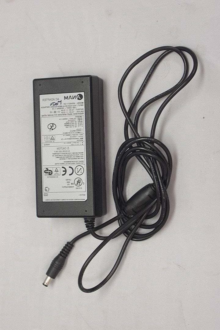
Click to zoom
Application Details
- Equipment Class
- JBP - Part 15 Class B Computing Device Peripheral
- Date of Grant
- Oct 27, 2002
- Application Purpose
- Original Equipment
- Date of Application
- Oct 27, 2002
- Equipment Note
- 17" LCD Monitor
- Company
- IMRI CO.,LTD.
- Country
- South Korea
Documents & Files
Document Text
Text extracted from the exhibit documents filed with the FCC. Open a document above to read the original.
Users Manual
Test Report No.: GETEC-E3-02-019 FCC Class B Certification APPENDIX H : USER’S MANUAL EUT Type: 17” TFT LCD Monitor FCC ID: OMNB17SM USERS MANUAL TFT LCD MONITOR B17SM ACCUVISION 720TF IMRI FCC Compliance Statement NOTE: This equipment has been tested and found to comply with the limits for a Class B digital device, pursuant to Part 15 of FCC Rules. These limits are designed to provide reasonable protection against harmful interference in a residential installation. This equipment generates, uses, and ca radiate radio frequency energy and, of not installed and used in accordance with the instructions, may cause harmful interference to radio communications. However, there is no guarantee that interference will not occur in a particular installation. If this equipment does cause harmful interference to radio or television reception, which can be determined by turning the equipment off and on, the user is encouraged to try to correct the interference by one or more of the following measures: - Reorient or relocate the receiving antenna. - Increase the separation between the equipment and receiver - Connect the equipment into an outlet on a circuit different from that to which the receiver is connected. - Consult the dealer or an experienced radio/television technician for help. Notice 1: The changes or modifications not expressly approved by the party responsible for compliance could void the user’s authority to operate the equipment. Notice 2: Shielded interface cables, if any, must be used in order to comply with the emission limits. DOC CLASS B NOTICE This digital apparatus does not exceed Class limits for radio noise emission for a digital apparatus as set out in the Radio interference Regulations of the Canadian Department of Communications. ● WARNING WARNING: To reduce the risk of electric shock do not remove cover (or rear). No user serviceable parts inside. Refer servicing to qualified service personnel. The lightning flash with arrowhead symbol, within an equilateral triangle, is intended to alert the user to the presence of uninsulated “dangerous voltage” within the product enclosure that may be of sufficient magnitude to constitute a risk of electric shock to persons. The exclamation point within an equilateral triangle is intended to alert the user to the presence of important operating and maintenance (servicing) instructions in the literature accompanying the appliance. WARNING: To prevent fire or shock hazard, do not expose the set to rain or moisture. Do not rub or strike the Active Matrix LCD with anything hard as this may scratch, mar, or damage the Active Matrix LCD permanently. CAUTION: Do not attempt to modify this product in any way without written authorization from a source of supply. Unauthorized modification could void the user’s authority to operate this product. Power This set operates on a DC supply provided by the AC-DC adaptor, the voltage is as indicated on the label on the rear cover. Use only the AC-DC adaptor supplied with the set and never applies an AC mains to the set directly. The AC-DC adaptor operates on an AC mains supply, the voltage is as indicated on the label of the AC-DC adaptor. a. Connect the DC plug of the AC-DC adaptor to the power socket of the set. b. Connect the AC-DC adaptor and it’s power cord. c. Connect the power cord to an AC mains. In the event of thunderstorms or power cuts, please pull out the mains plug of the AC-DC adaptor and the aerial plug. Do not allow anything to rest upon or roll over the power cord, and do not place the set where the power cord is subject to damage. Service Never remove the rear cover of the set, this can expose you to high voltage and other hazards. If the set does not operate properly, unplug it and call your dealer. Antenna Connect the antenna cable to the connection marked ANTENNA.(on the rear). For the best reception, use an outdoor antenna. - 1- Location Position your set so that no bright light or sunlight will shine directly on the screen. Do not expose the set to vibration, moisture, dust or heat. Also ensure that the set is placed in a position that allows a free flow of air. Do not cover the ventilation openings on the rear cover. You can install the set on a wall or place it on a table-top or similar flat surface. Mounted the set securely to eliminate the risk of injury from the set falling. Contact your Zenith dealer to purchase the optional ceiling mount. Cleaning Unplug the set before cleaning the face of the LCD Screen. Dust the set by wiping the screen and the cabinet with a soft, clean cloth. If the screen requires additional cleaning, use a clean, damp cloth. Do not use liquid cleaners or aerosol cleaners. - 2 - Table of Contents 1) Safety instructions -------------------------- 1-2 2) Table of contents -------------------------- 3 3) Specifications (1) Features -------------------------- 4 (2) Setting up your monitor front / rear -------------------------- 5 4) Installing your monitor (1) Basic contents -------------------------- 6 (2) Installing your monitor -------------------------- 6 (3) Assembling your monitor ① Assembling the Stand & Base ----------------------- 7 ② Connecting the Power & Signal cable ----------------------- 8 5) Adjusting your monitor (1) PC ① Adjusting Brightness -------------------------- 9 ② Adjusting Contrast -------------------------- 9 ③ Adjusting Phase -------------------------- 10 ④ Adjusting Frequency -------------------------- 10 ⑤ Adjusting Screen Position(H/V) -------------------------- 10 ⑥ Adjusting Sharpness -------------------------- 10 (2) OSD ① Menu Position Adjustments -------------------------- 11 ② OSD Timeout Adjustments -------------------------- 11 ③ Language Adjustments -------------------------- 12 (3) UTILITY ① Monitor Information -------------------------- 12 ② Resting the Monitor -------------------------- 13 ③ Adjusting the Tone(Transparency) -------------------------- 13 ④ Color Temperature Adjustments -------------------------- 1…
Text truncated - open the document above for the full version.
Block Diagram
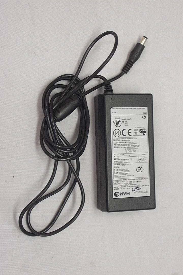
Test Report No.: GETEC-E3-02-019 FCC Class B Certification APPENDIX D : BLOCK DIAGRAM EUT Type: 17” TFT LCD Monitor FCC ID : OMNB17SM B17SM Block Description Model “B17SM”use a new concept display panel. The panel “LTM170EI-A01”manufactured by SAMSUNG Electronics Co.,Ltd. provides total display functions just like an integrated circuit. It includes an inverter board, LSP ( LCD signal process ) board, source board, 4 lamps and LCD panel as below “Block Diagram” Block Diagram IMRI Co.,Ltd Design Block SAMSUNG SOP Block (System –ON –Panel) Type No. : LTM170EI-A01 (LCD Signal Process board) Anam Instruments Co.,Ltd Model No.:AP04211-UV 12VDC, 3.5A output Adapter Technical Information of “LTM170EI-A01”
External Photos
Test Report No.: GETEC-E3-02-019 FCC Class B Certification APPENDIX F : EXTERNAL PHOTOGRAPHS EUT Type: 17” TFT LCD Monitor FCC ID : OMNB17SM Test Report No.: GETEC-E3-02-019 FCC Class B Certification EUT Type: 17” TFT LCD Monitor FCC ID : OMNB17SM Test Report No.: GETEC-E3-02-019 FCC Class B Certification EUT Type: 17” TFT LCD Monitor FCC ID : OMNB17SM Test Report No.: GETEC-E3-02-019 FCC Class B Certification EUT Type: 17” TFT LCD Monitor FCC ID : OMNB17SM Test Report No.: GETEC-E3-02-019 FCC Class B Certification EUT Type: 17” TFT LCD Monitor FCC ID : OMNB17SM EUT Type: 17” TFT LCD Monitor FCC ID : OMNB17SM Test Report No.: GETEC-E3-02-019 FCC Class B Certification
ID Label/Location Info
Test Report No.: GETEC-E3-02-019 FCC Class B Certification APPENDIX C : ID SAMPLE LABEL & LOCATION EUT Type: 17” TFT LCD Monitor FCC ID : OMNB17SM EUT Type: 17” TFT LCD Monitor FCC ID : OMNB17SM Test Report No.: GETEC-E3-02-019 FCC Class B Certification LABELLING REQUIREMENTS The label shown shall be permanently affixed at a conspicuous location on the device and be readily visible to the user at the time of purchase. ID Label ID Label Location of EUT I.D Label
Internal Photos
Test Report No.: GETEC-E3-02-019 FCC Class B Certification APPENDIX G : INTERNAL PHOTOGRAPHS EUT Type: 17” TFT LCD Monitor FCC ID : OMNB17SM Test Report No.: GETEC-E3-02-019 FCC Class B Certification EUT Type: 17” TFT LCD Monitor FCC ID : OMNB17SM Test Report No.: GETEC-E3-02-019 FCC Class B Certification EUT Type: 17” TFT LCD Monitor FCC ID : OMNB17SM Test Report No.: GETEC-E3-02-019 FCC Class B Certification EUT Type: 17” TFT LCD Monitor FCC ID : OMNB17SM Test Report No.: GETEC-E3-02-019 FCC Class B Certification EUT Type: 17” TFT LCD Monitor FCC ID : OMNB17SM Test Report No.: GETEC-E3-02-019 FCC Class B Certification EUT Type: 17” TFT LCD Monitor FCC ID : OMNB17SM Test Report No.: GETEC-E3-02-019 FCC Class B Certification EUT Type: 17” TFT LCD Monitor FCC ID : OMNB17SM Test Report No.: GETEC-E3-02-019 FCC Class B Certification EUT Type: 17” TFT LCD Monitor FCC ID : OMNB17SM Test Report No.: GETEC-E3-02-019 FCC Class B Certification EUT Type: 17” TFT LCD Monitor FCC ID : OMNB17SM Test Report No.: GETEC-E3-02-019 FCC Class B Certification EUT Type: 17” TFT LCD Monitor FCC ID : OMNB17SM Test Report No.: GETEC-E3-02-019 FCC Class B Certification EUT Type: 17” TFT LCD Monitor FCC ID : OMNB17SM Test Report No.: GETEC-E3-02-019 FCC Class B Certification EUT Type: 17” TFT LCD Monitor FCC ID : OMNB17SM Test Report No.: GETEC-E3-02-019 FCC Class B Certification EUT Type: 17” TFT LCD Monitor FCC ID : OMNB17SM Test Report No.: GETEC-E3-02-019 FCC Class B Certification EUT Type: 17” TFT LCD Monitor FCC ID : OMNB17SM Test Report No.: GETEC-E3-02-019 FCC Class B Certification EUT Type: 17” TFT LCD Monitor FCC ID : OMNB17SM Test Report No.: GETEC-E3-02-019 FCC Class B Certification EUT Type: 17” TFT LCD Monitor FCC ID : OMNB17SM Test Report No.: GETEC-E3-02-019 FCC Class B Certification EUT Type: 17” TFT LCD Monitor FCC ID : OMNB17SM Test Report No.: GETEC-E3-02-019 FCC Class B Certification EUT Type: 17” TFT LCD Monitor FCC ID : OMNB17SM EUT Type: 17” TFT LCD Monitor FCC ID : OMNB17SM Test Report No.: GETEC-E3-02-019 FCC Class B Certification
Test Report
Test Report No.: GETEC-E3-02-019 FCC Class B Certification CONTENTS 1. SCOPE .........................................................................................................................................................................3 2. INTRODUCTION.....................................................................................................................................................4 3. TEST CONDITIONS & EUT INFORMATION...............................................................................................5 3.1 D ESCRIPTION OF EUT.............................................................................................................................................5 3.2 S UPPORT E QUIPMENT USED .....................................................................................................................................6 4 . DESCRIPTION OF TESTS....................................................................................................................................7 4.1 C ONDUCTED E MISSION............................................................................................................................................7 4.2 R ADIATED E MISSIONS..............................................................................................................................................8 5. CONDUCTED EMISSIONS..................................................................................................................................9 5.1 O PERATING ENVIRONMENT.....................................................................................................................................9 5.2 T EST SET - UP .............................................................................................................................................................9 5.3 MEASUREMENT UNCERTAINTY ................................................................................................................................9 5.4 L IMIT......................................................................................................................................................................10 5.5 T EST EQUIPMENT USED..........................................................................................................................................10 5.6 T EST DATA FOR CONDUCTED EMISSION .................................................................................................................11 6. RADIATED EMISSIONS .....................................................................................................................................13 6.1 O PERATING ENVIRONMENT ...................................................................................................................................13 6.2 TEST SET - UP ...........................................................................................................................................................13 6.3 M EASUREMENT UNCERTAINTY ..............................................................................................................................13 6.4 L IMIT......................................................................................................................................................................14 6.5 T EST EQUIPMENT USED..........................................................................................................................................14 6.5 T EST DATA FOR RADIATED EMISSION....................................................................................................................15 7. SAMPLE CALCULATIONS ...............................................................................................................................16 7.1 E XAMPLE 1 :...........................................................................................................................................................16 7.2 E XAMPLE 2 :...........................................................................................................................................................16 8. RECOMMENDATION & CONCLUSION ......................................................................................................17 APPENDIX A – ATTESTATION STATEMENT APPENDIX B – PLOTS OF CONDUCTED EMISSIONS APPENDIX C – ID SAMPLE LABEL & LOCATION APPENDIX D – BLOCK DIAGRAM APPENDIX E – TEST SET-UP PHOTOGRAPHS APPENDIX F – EXTERNAL PHOTOGRAPHS APPENDIX G –INTERNAL PHOTOGRAPHS APPENDIX H – USER’S MANUAL EUT Type: 17” TFT LCD Monitor FCC ID : OMNB17SM P age 2 of 17 Test Report No.: GETEC-E3-02-019 FCC Class B Certification 1. Scope Measurement and determination of electromagnetic emissions (EME) of radio frequency devices including intentional and / or unintentional radiators for compliance with technical rules and regulations of the Federal Communications Commission . Responsible Party: IMRI Co., Ltd. Contact Person: Young – Beom Park, Deputy Manager / R&D Dept. Manufacturer: 270-2, Hunshin-Dong, Sangju-City, Gyeongsangbuk-Do, Korea Tel No.: +82-54-534-7943 z FCC ID OMNB17SM z Equipment Class Class B Computing Device Peripheral z EUT Type 17” TFT LCD Monitor z Model No. B17SM z Max. Resolution 1280×1024 Non-interlaced @ 75Hz z Frequency Range H-Sync: 30kHz – 80kHz V-Sync: 55Hz – 75Hz z Tra de Na me IMRI z AC/DC Adapter AP04211-UV (ANAM Instruments Co., Ltd.) Input: 100~240VAC 50/60Hz 1.1A Output: 12VDC 3.5A z Rule Part(s) FCC Part 15 Subparts B z Standard(s) EN55022:1998 (CISPR22:1997) z Test Procedure(s) ANSI C63.4 (1992) z Dates of Test October 05 ~ 08, 2002 z Place of Test Gumi College EMC Center z Test Report No. GETEC-E3-02-019 EUT Type: 17” TFT LCD Monitor FCC ID : OMNB17SM P age 3 of 17 Test Report No.: GETEC-E3-02-019 FCC Class B Certification 2. Introduction The measurement procedure described in American National Standard for Methods of Measurement of Radio-Nose Emissions From Low-Vol…
Text truncated - open the document above for the full version.
Test Report
Test Report No.: GETEC-E3-02-019 FCC Class B Certification APPENDIX B : PLOTS OF CONDUCTED EMISSIONS EUT Type: 17” TFT LCD Monitor FCC ID : OMNB17SM Test Report No.: GETEC-E3-02-019 FCC Class B Certification ■ Test Mode : 1280*1024 / 75Hz < Hot line > EUT Type: 17” TFT LCD Monitor FCC ID : OMNB17SM Test Report No.: GETEC-E3-02-019 FCC Class B Certification < Neutral line > EUT Type: 17” TFT LCD Monitor FCC ID : OMNB17SM Test Report No.: GETEC-E3-02-019 FCC Class B Certification ■ Test Mode : 1024*768 / 75Hz < Hot line > EUT Type: 17” TFT LCD Monitor FCC ID : OMNB17SM Test Report No.: GETEC-E3-02-019 FCC Class B Certification < Neutral line > EUT Type: 17” TFT LCD Monitor FCC ID : OMNB17SM Test Report No.: GETEC-E3-02-019 FCC Class B Certification ■ Test Mode : 800*600 / 60Hz < Hot line > EUT Type: 17” TFT LCD Monitor FCC ID : OMNB17SM EUT Type: 17” TFT LCD Monitor FCC ID : OMNB17SM Test Report No.: GETEC-E3-02-019 FCC Class B Certification < Neutral line >
Test Setup Photos
Test Report No.: GETEC-E3-02-019 FCC Class B Certification APPENDIX E : TEST SET UP PHOTOGRAPHS EUT Type: 17” TFT LCD Monitor FCC ID : OMNB17SM Test Report No.: GETEC-E3-02-019 FCC Class B Certification The Conducted Test Picture and Radiated Test Picture show the worst-case configuration and cable placement. Conducted Test Picture (Front) Conducted Test Picture (Rear) EUT Type: 17” TFT LCD Monitor FCC ID : OMNB17SM EUT Type: 17” TFT LCD Monitor FCC ID : OMNB17SM Test Report No.: GETEC-E3-02-019 FCC Class B Certification Radiated Test Picture (Front ) Radiated Test Picture (Rear )
Contact Information
Applicant
JOON WHANG(MANAGER OF PRODUCT PLANNING DEPT.)
Test Firm
Gumi University EMC CenterTae-Sig Park
Technical Specifications
| # | Rule Parts | Frequency Range | Power Output |
|---|---|---|---|
| 1 | 15B | - | - |
Other Applications from IMRI CO.,LTD.
OMNE19XA
Oct 28, 200219" LCD Monitor
Equipment Class
JBP - Part 15 Class B Computing Device Peripheral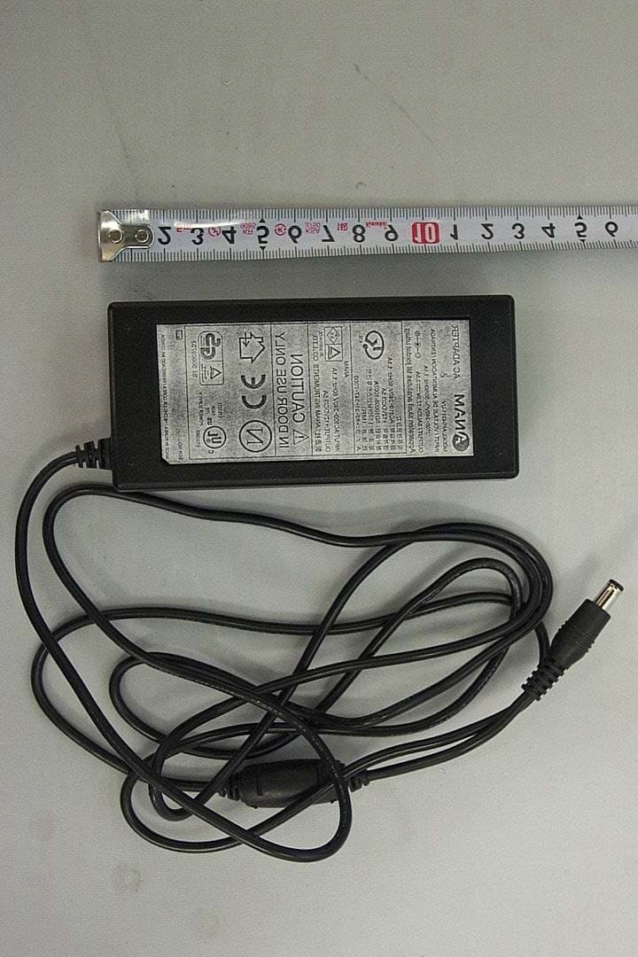
OMNE15XA
Jul 22, 200215" LCD Monitor
Equipment Class
JBP - Part 15 Class B Computing Device Peripheral
OMNB19BL
Mar 07, 200219" CRT Monitor
Equipment Class
JBP - Part 15 Class B Computing Device Peripheral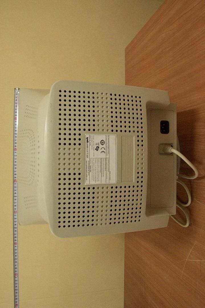
OMNB19BF
Feb 19, 200219" CRT Monitor
Equipment Class
JBP - Part 15 Class B Computing Device Peripheral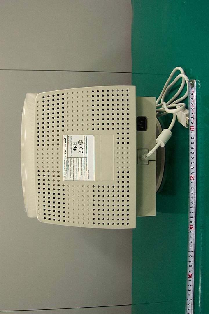
OMNE17CL
Jan 22, 200217" CRT Monitor
Equipment Class
JBP - Part 15 Class B Computing Device Peripheral