ON8WMO2-G1900WMO2 MODEM SERIES GSM 1900
Wavecom Inc
Click to zoom
Application Details
- Equipment Class
- TNB - Licensed Non-Broadcast Station Transmitter
- Date of Grant
- Feb 15, 2000
- Application Purpose
- Original Equipment
- Date of Application
- Aug 11, 1999
- Equipment Note
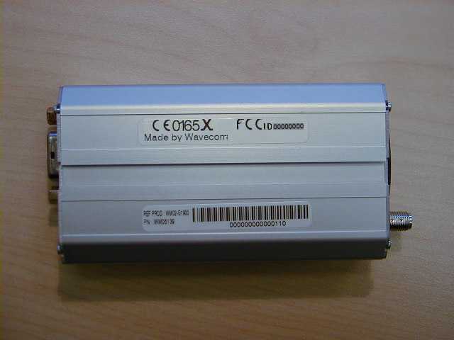
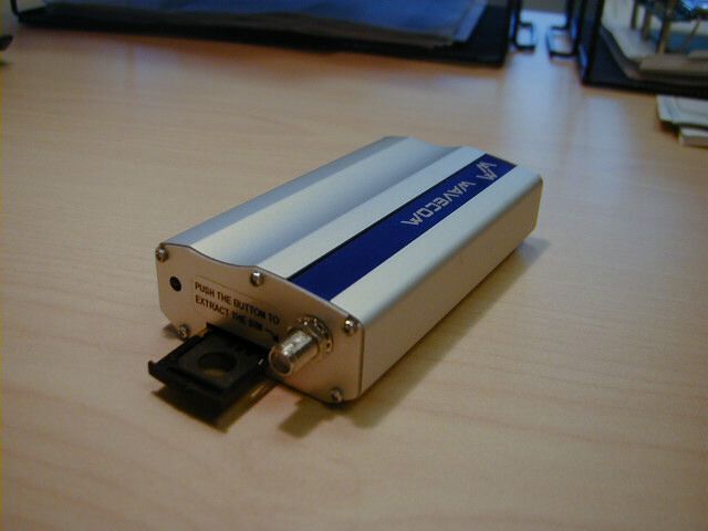
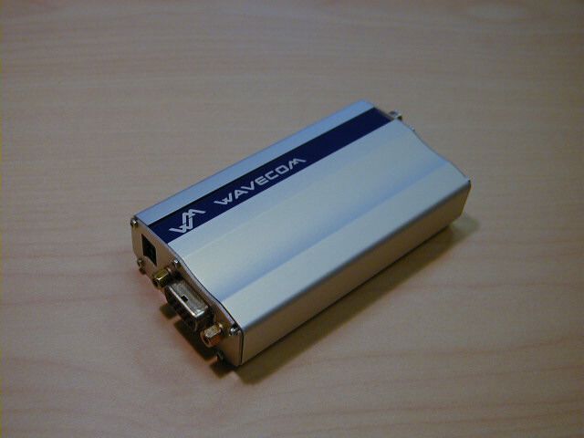
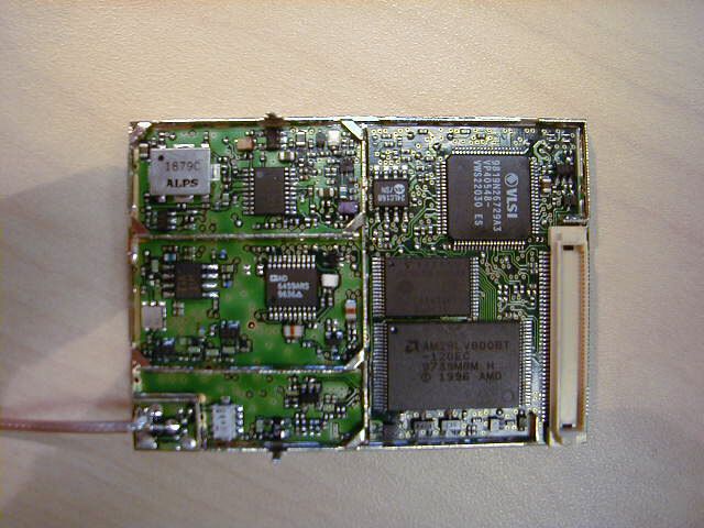
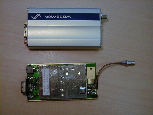
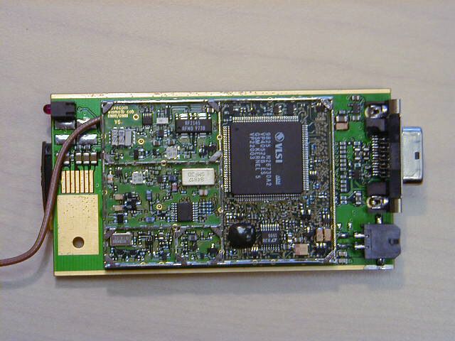
- WMO2 MODEM SERIES GSM 1900
- Frequency Range
- 1850.00000000 - 1910.00000000
- Company
- Wavecom Inc
- Country
- United States
Documents & Files
Document Text
Text extracted from the exhibit documents filed with the FCC. Open a document above to read the original.
Users Manual
USER MANUAL WMO2 Modem Series GSM 900 / 1800 / 1900 SUMMARY 1. PRODUCT DESCRIPTION1 1.1 Package content1 1.2 Product presentation1 1.3 Physical characteristics2 1.4 Functions2 1.5 Temperature range2 2. INSTALLATION/START-UP3 2.1 Mounting the modem3 2.2 Installing the modem3 2.3 Electrical characteristics4 2.3.1 Switching the GSM modem on/off4 2.3.2 Voltage range4 2.3.3 Overvoltage/undervoltage4 2.3.4 Power supply cable5 2.3.5 Electrical characteristics defined in input/output for all external connections6 2.3.6 Protection/on-board network connection6 3. DESCRIPTION OF THE INTERFACES7 3.1 SIM card holder7 3.2 LED Function8 3.3 Connectors8 4. GETTING STARTED11 SUMMARY Wavecom GSM Modem 5. TROUBLESHOOTING12 5.1 Specific defaults possibly encountered12 5.1.1 The modem does not answer through the serial link12 5.1.2 The modem always returns « Error » when trying to issue a communication13 5.1.3 The modem always returns «No carrier » when trying to issue a communication14 6. NOTES ON SAFETY16 6.1 General safety16 6.2 Vehicle safety17 6.3 Car and Maintenance17 6.4 Your responsibility18 7. GENERAL INFORMATIONS19 SUMMARY Wavecom GSM Modem 1. PRODUCT DESCRIPTION 1.1Package content The Wavecom GSM modem package comprises: - Modem - 2 holding bridles - Power supply cable + fuse - User manual (this document) 1.2Product presentation The Wavecom GSM modem is a terminal for fax and data transmission, short message service mobile originated, short message service mobile terminated and voice calls. Connectors binded to the body guarantee output and input connections. An extractible holder is used to insert the SIM card (Micro-SIM type). A LED function indicates the working mode. No cordon is fixed to the case. Figure 1 Modem presentation schema PRODUCT DESCRIPTION Wavecom GSM Modem1 Micro-Fit connector TM SUB HD connector Front cap LED Extractible SIM holder SMA connecto r Back cap 1.3Physical characteristics 1.4Functions - GSM Modes 1.5Temperature range Operating conditions :From -20°C to +55°C Storage conditions:From -25°C to +70°C PRODUCT DESCRIPTION Wavecom GSM Modem2 snoisnemiD)srotcennocgnidulcxe(mm52x45x89 snoisnemidllarevOmm52x45x011 thgieWsemmarg041< emuloV3mc32.31 gnisuoHdeliforpmuinimulA dradnatS2esahPMSG)W1(1ssalCzHM0091/0081-)W2(4ssalCzHM009 ecafretnI noitcnufgniduabotuA82.V/42.V232SRecafretnilaireS 70.70&50.70MSGdnaret52.VnodesabtesdnammocTA SMS .)TM(detanimreTeliboMdna)OM(detanigirOeliboM .tsacdaorblleC.tniopottniopUDP&txeTedoM .50.70MSGhtiwecnadroccanI ataD .s/stib0069,0084,0042suonorhcnysA .edomtnerapsnarTnoNdnatnerapsnarT .sduab57/0021,0021,003:edoMtnerapsnarTnoNnI .)NDSI(011Vdna)NTSP(zHK1.3edoM xaF s/stib0069/0027/0084/0042 .edoMtnerapsnarTni26ecivreseletMSG .elbitapmoc3epuorG.1ssalC oiduA)noitponi(tikraC:2)noitponi(tesdaeH:1:seirosseccA-RFE+RF 2INSTALLATION/START-UP 2.1Mounting the modem For mounting the modem, bind to the body the holding bridles according to the schema below: Figure 2 Modem mounting 2.2Installing the modem To install the modem, plug the device on a DC power supply (for automotive application, connect the device on the permanent « + » and insert the SIM card in the holder). Make sure that an antenna is connected. In order to extract or to insert the Micro SIM card, it is imperative to press the SIM holder ejector with a sharp element (a pen for example). If this order is not respected, the SIM holder could be damaged. INSTALLATION/START-UP Wavecom GSM Modem3 Note : - To be attached to a plain surface - Screw head max. height: 2mm 2 m m Holding bridles 2 mm 2.3Electrical characteristics 2.3.1 Switching the GSM modem on/off The device is permanently powered (when connected to the power supply). 2.3.2 Voltage range Voltage range:5 to 32V DC (GSM 900) - 6 to 32V DC (GSM 1800/1900) GND:0V 2.3.3 Overvoltage/undervoltage Correct operation of the GSM Wavecom modem in send mode is not guaranteed if input voltage fall below 5V (GSM 900) - 6V (GSM 1800/1900). The modem is protected against voltage over 32V. When input voltages exceed 32V, the supply voltage is disconnected in order to protect the electronic components from an overvoltage. TWO CASES ARE POSSIBLE: - IF THE OVERVOLTAGE IS CONTINUOUS, THE PROTECTION IS GUARANTEED BY THE FUSE. - IN THE CASE OF TRANSIENT PEAKS, THE MODEM GUARANTEES ITS OWN PROTECTION. INSTALLATION/START-UP Wavecom GSM Modem4 2.3.4 Power supply cable A cable, included in the package shall be used for power supply connection. The wires are marked as follows: Cable:1 wire Ame:tinned copper 24x0.2 mm Section:0.75 mm ̋ Figure 3 Power supply cable schema INSTALLATION/START-UP Wavecom GSM Modem5 + - Side view Connector Molex Micro-Fit 3.0 T M Cables stripped over 200 mm, protected by their own sheath Standard cable sheath Stripped wire, tinned over 5 m m 2.3.5 Electrical characteristics defined in input/output for all external connections 2.3.6 Protection/on-board network connection The modem installed is protected by a fuse directly binded on the power supply cable. INSTALLATION/START-UP Wavecom GSM Modem6 sretemaraPsretemaraP sretemaraP sretemaraPsretemaraP 009MSG009MSG 009MSG 009MSG009MSG0091/0081MSG0091/0081MSG 0091/0081MSG 0091/0081MSG0091/0081MSG tinUtinU tinU tinUtinU .niM.niM .niM .niM.niM.pyT.pyT .pyT .pyT.pyT.xaM.xaM .xaM .xaM.xaM.niM.niM .niM .niM.niM.pyT.pyT .pyT .pyT.pyT.xaM.xaM .xaM .xaM.xaM :ylppusrewoP:ylppusrewoP :ylppusrewoP :ylppusrewoP:ylppusrewoP egatlovylppustupnI-523623V noitpotiKraChtiwegatlovylppustupnI-8181V tnerrucylppuskaeptupnI-5.21A -edomnoitacinummocnitnerrucylppusegarevatupnI054002Am edomeldinitnerrucylppusegarevatupnI-0353Am :knillaireS:knillaireS :knillaireS :knillaireS:knillaireS232SR- :)tesdaeh(oiduA:)tesdaeh(oiduA :)tesdaeh(oiduA :)tesdaeh(oiduA:)tesdaeh(oiduA K2/V2@tnerructupnienohporciM-Ω5.05.0Am egatlovtupnienohporcimetulosbA-001001pVm 051tnerructuptuorekaepS-ΩFn1/6161Am ecnadepmirekaepsetulosbA-2323 Ω MISMIS MIS MISMIS 5ro3V 3. DESCRIPTION OF THE INTERFACES The modem comprises several interfaces: - SIM card holder - C…
Text truncated - open the document above for the full version.
Users Manual
USER MANUAL WMO2 Modem Series GSM 900 / 1800 / 1900 SUMMARY 1. PRODUCT DESCRIPTION1 1.1 Package content1 1.2 Product presentation1 1.3 Physical characteristics2 1.4 Functions - GSM Modes2 1.5 Temperature range2 2. INSTALLATION/START-UP3 2.1 Mounting the modem3 2.2 Installing the modem3 2.3 Electrical characteristics4 2.3.1 Switching the GSM modem on/off4 2.3.2 Voltage range4 2.3.3 Overvoltage/undervoltage4 2.3.4 Power supply cable5 2.3.5 Input/output electrical characteristics defined for all external connections6 2.3.6 Protection/on-board network connection6 3. DESCRIPTION OF THE INTERFACES7 3.1 LED Function7 3.2 Connectors7 4. TECHNICAL DATA11 SUMMARY Wavecom WMO2 Modem 5. TROUBLESHOOTING: Specific defaults possibly encountered12 5.1 The modem does not answer through the serial link12 5.2 The modem always returns «Error» when trying to issue a communication13 5.3 The modem always returns «No carrier» when trying to issue a communication14 6. NOTES ON SAFETY16 6.1 General safety16 6.2 Vehicle safety17 6.3 Car And Maintenance17 6.4 Your responsibility18 7. GENERAL INFORMATIONS19 SUMMARY Wavecom WMO2 Modem 1. PRODUCT DESCRIPTION The Wavecom WMO2 modem exist under three different references: - WMO2-G900:GSM 900 MHz version - WMO2-G1800 :GSM 1800 MHz version - WMO2-G1900 :GSM 1900 MHz version 1.1Package content The Wavecom WMO2 modem package comprises: - 1 Modem - 2 holding bridles - 1 Power supply cable + fuse - 1 User manual (this document) 1.2Product presentation The Wavecom WMO2 modem is a terminal for fax and data transmission, short message service mobile originated, short message service mobile terminated and voice calls. The connectors binded to the body guarantee output and input connections. An extractible holder is used to insert the SIM card (Micro-SIM type). A LED indicates the operating mode. PRODUCT DESCRIPTION Wavecom WMO2 Modem1 Micro-Fit connector TM SUB HD connector Front cap LED Extractible SIM holder SMA connecto r Back cap Figure 1 Modem presentation 1.3Physical characteristics 1.4Functions - GSM Modes 1.5Temperature range Operating conditions :From -20°C to +55°C Storage conditions:From -25°C to +70°C PRODUCT DESCRIPTION Wavecom WMO2 Modem2 dradnatS2esahPMSG)W1(1ssalCzHM0091/0081-)W2(4ssalCzHM009 ecafretnI noitcnufgniduabotuA82.V/42.V232SRecafretnilaireS 70.70&50.70MSGdnaret52.VnodesabtesdnammocTA SMS .)TM(detanimreTeliboMdna)OM(detanigirOeliboM .tsacdaorblleC.tniopottniopUDP&txeTedoM .50.70MSGhtiwecnadroccanI ataD .s/stib0069,0084,0042suonorhcnysA .edomtnerapsnarTnoNdnatnerapsnarT .sduab57/0021,0021,003:ylnoedoMtnerapsnarTnoNnI .)NDSI(011Vdna)NTSP(zHK1.3edoM xaF s/stib0069/0027/0084/0042 .edoMtnerapsnarTni26ecivreseletMSG .elbitapmoc3epuorG.1ssalC oiduAtesdaeH:seirosseccA-RFE+RF snoisnemiD)srotcennocgnidulcxe(mm52x45x89 snoisnemidllarevOmm52x45x011 thgieWsmarg041< emuloV3mc32.31 gnisuoHdeliforpmuinimulA 2INSTALLATION/START-UP 2.1Mounting the modem For mounting the modem, bind to the body the holding bridles according to the schema below: Figure 2 Modem mounting 2.2Installing the modem To install the modem, plug the device on a DC power supply (for automotive application, connect the device on the permanent « + » and insert the SIM card in the holder). Make sure that an antenna is connected. In order to extract or to insert the Micro SIM card, it is necessary to press the SIM holder ejector with a sharp element (a pen for example). If this sequence is not respected, the SIM holder could be damaged. INSTALLATION/START-UP Wavecom WMO2 Modem3 Note: - To be attached to a plain surface - Screw head max. height: 2mm 2 m m Holding bridles 2 mm 2.3Electrical characteristics 2.3.1 Switching the GSM modem on/off The device is permanently powered (when connected to the power supply). 2.3.2 Voltage range Voltage range:5 to 32V DC (GSM 900) - 6 to 32V DC (GSM 1800/1900) GND:0V 2.3.3 Overvoltage/undervoltage Correct operation of the Wavecom WMO2 modem in communication mode is not guaranteed if input voltage fall below 5V (GSM 900) - 6V (GSM 1800/1900). The modem is protected against voltage over 32V. When input voltages exceed 32V, the supply voltage is disconnected in order to protect the electronic components from an overvoltage. TWO CASES ARE POSSIBLE: - IF THE OVERVOLTAGE IS CONTINUOUS, THE PROTECTION IS GUARANTEED BY THE FUSE. - IN THE CASE OF TRANSIENT PEAKS, THE MODEM GUARANTEES ITS OWN PROTECTION. INSTALLATION/START-UP Wavecom WMO2 Modem4 2.3.4 Power supply cable A cable, included in the package shall be used for power supply connection. The wires are marked as follows: Cable:1 wire Ame:tinned copper 24x0.2 mm Section:0.75 mm 2 Figure 3 Power supply cable INSTALLATION/START-UP Wavecom WMO2 Modem5 + - Side view Connector Molex Micro-Fit 3.0 T M Cables stripped over 200 mm, protected by their own sheath Standard cable sheath Stripped wire, tinned over 5 m m - + 2.3.5 Input/output electrical characteristics defined for all external connections 2.3.6 Protection/on-board network connection The modem is protected by a fuse directly binded on the power supply cable. INSTALLATION/START-UP Wavecom WMO2 Modem6 sretemaraP 009MSG0091/0081MSG tinU .niM.pyT.xaM.niM.pyT.xaM :ylppusrewoP egatlovylppustupnI-523623V noitpotiKraChtiwegatlovylppustupnI-8181V tnerrucylppuskaeptupnI-5.21A -edomnoitacinummocnitnerrucylppusegarevatupnI054002Am edomeldinitnerrucylppusegarevatupnI-0353Am :knillaireS232SR- :)tesdaeh(oiduA K2/V2@tnerructupnienohporciM-Ω5.05.0Am egatlovtupnienohporcimetulosbA-001001pVm 051tnerructuptuorekaepS-ΩFn1/6161Am ecnadepmirekaepsetulosbA-2323 Ω MIS5ro35ro3V 3. DESCRIPTION OF THE INTERFACES The modem comprises several interfaces: - LED function indicating operating status - External antenna (via SMA) - Serial and control link (via 15 pins SUB D) - Power supply (via 4 pins Micro-Fit TM ) - SIM card holder 3.1LED Function - LED offDevice switched off - Not ready - LED onDevice switched on - Connecting to network - LED flashing slowlyDevice switched on - Idle mode - LED flashing ra…
Text truncated - open the document above for the full version.
Users Manual
USER MANUAL WMO2 Modem Series GSM 900 / 1800 / 1900 SUMMARY 1. PRODUCT DESCRIPTION1 1.1 Package content1 1.2 Product presentation1 1.3 Physical characteristics2 1.4 Functions - GSM Modes2 1.5 Temperature range2 2. INSTALLATION/START-UP3 2.1 Mounting the modem3 2.2 Installing the modem3 2.3 Electrical characteristics4 2.3.1 Switching the GSM modem on/off4 2.3.2 Voltage range4 2.3.3 Overvoltage/undervoltage4 2.3.4 Power supply cable5 2.3.5 Input/output electrical characteristics defined for all external connections6 2.3.6 Protection/on-board network connection6 3. DESCRIPTION OF THE INTERFACES7 3.1 LED Function7 3.2 Connectors7 4. TECHNICAL DATA11 SUMMARY Wavecom WMO2 Modem 5. TROUBLESHOOTING: Specific defaults possibly encountered12 5.1 The modem does not answer through the serial link12 5.2 The modem always returns «Error» when trying to issue a communication13 5.3 The modem always returns «No carrier» when trying to issue a communication14 6. NOTES ON SAFETY16 6.1 General safety16 6.2 Vehicle safety17 6.3 Car And Maintenance17 6.4 Your responsibility18 7. RF EXPOSURE INSTRUCTIONS19 8. INSTRUCTION TO OEM20 9. GENERAL INFORMATIONS21 SUMMARY Wavecom WMO2 Modem 1. PRODUCT DESCRIPTION The Wavecom WMO2 modem exist under three different references: - WMO2-G900:GSM 900 MHz version - WMO2-G1800 :GSM 1800 MHz version - WMO2-G1900 :GSM 1900 MHz version 1.1Package content The Wavecom WMO2 modem package comprises: - 1 Modem - 2 holding bridles - 1 Power supply cable + fuse - 1 User manual (this document) 1.2Product presentation The Wavecom WMO2 modem is a terminal for fax and data transmission, short message service mobile originated, short message service mobile terminated and voice calls. The connectors binded to the body guarantee output and input connections. An extractible holder is used to insert the SIM card (Micro-SIM type). A LED indicates the operating mode. PRODUCT DESCRIPTION Wavecom WMO2 Modem1 Micro-Fit connector TM SUB HD connector Front cap LED Extractible SIM holder SMA connecto r Back cap Figure 1 Modem presentation 1.3Physical characteristics 1.4Functions - GSM Modes 1.5Temperature range Operating conditions :From -20°C to +55°C Storage conditions:From -25°C to +70°C PRODUCT DESCRIPTION Wavecom WMO2 Modem2 dradnatS2esahPMSG)W1(1ssalCzHM0091/0081-)W2(4ssalCzHM009 ecafretnI noitcnufgniduabotuA82.V/42.V232SRecafretnilaireS 70.70&50.70MSGdnaret52.VnodesabtesdnammocTA SMS .)TM(detanimreTeliboMdna)OM(detanigirOeliboM .tsacdaorblleC.tniopottniopUDP&txeTedoM .50.70MSGhtiwecnadroccanI ataD .s/stib0069,0084,0042suonorhcnysA .edomtnerapsnarTnoNdnatnerapsnarT .sduab57/0021,0021,003:ylnoedoMtnerapsnarTnoNnI .)NDSI(011Vdna)NTSP(zHK1.3edoM xaF s/stib0069/0027/0084/0042 .edoMtnerapsnarTni26ecivreseletMSG .elbitapmoc3epuorG.1ssalC oiduAtesdaeH:seirosseccA-RFE+RF snoisnemiD)srotcennocgnidulcxe(mm52x45x89 snoisnemidllarevOmm52x45x011 thgieWsmarg041< emuloV3mc32.31 gnisuoHdeliforpmuinimulA 2INSTALLATION/START-UP 2.1Mounting the modem For mounting the modem, bind to the body the holding bridles according to the schema below: Figure 2 Modem mounting 2.2Installing the modem To install the modem, plug the device on a DC power supply (for automotive application, connect the device on the permanent « + » and insert the SIM card in the holder). Make sure that an antenna is connected. In order to extract or to insert the Micro SIM card, it is necessary to press the SIM holder ejector with a sharp element (a pen for example). If this sequence is not respected, the SIM holder could be damaged. INSTALLATION/START-UP Wavecom WMO2 Modem3 Note: - To be attached to a plain surface - Screw head max. height: 2mm 2 m m Holding bridles 2 mm 2.3Electrical characteristics 2.3.1 Switching the GSM modem on/off The device is permanently powered (when connected to the power supply). 2.3.2 Voltage range Voltage range:5 to 32V DC (GSM 900) - 6 to 32V DC (GSM 1800/1900) GND:0V 2.3.3 Overvoltage/undervoltage Correct operation of the Wavecom WMO2 modem in communication mode is not guaranteed if input voltage fall below 5V (GSM 900) - 6V (GSM 1800/1900). The modem is protected against voltage over 32V. When input voltages exceed 32V, the supply voltage is disconnected in order to protect the electronic components from an overvoltage. TWO CASES ARE POSSIBLE: - IF THE OVERVOLTAGE IS CONTINUOUS, THE PROTECTION IS GUARANTEED BY THE FUSE. - IN THE CASE OF TRANSIENT PEAKS, THE MODEM GUARANTEES ITS OWN PROTECTION. INSTALLATION/START-UP Wavecom WMO2 Modem4 2.3.4 Power supply cable A cable, included in the package shall be used for power supply connection. The wires are marked as follows: Cable:1 wire Ame:tinned copper 24x0.2 mm Section:0.75 mm 2 Figure 3 Power supply cable INSTALLATION/START-UP Wavecom WMO2 Modem5 + - Side view Connector Molex Micro-Fit 3.0 T M Cables stripped over 200 mm, protected by their own sheath Standard cable sheath Stripped wire, tinned over 5 m m - + 2.3.5 Input/output electrical characteristics defined for all external connections 2.3.6 Protection/on-board network connection The modem is protected by a fuse directly binded on the power supply cable. INSTALLATION/START-UP Wavecom WMO2 Modem6 sretemaraP 009MSG0091/0081MSG tinU .niM.pyT.xaM.niM.pyT.xaM :ylppusrewoP egatlovylppustupnI-523623V noitpotiKraChtiwegatlovylppustupnI-8181V tnerrucylppuskaeptupnI-5.21A -edomnoitacinummocnitnerrucylppusegarevatupnI054002Am edomeldinitnerrucylppusegarevatupnI-0353Am :knillaireS232SR- :)tesdaeh(oiduA K2/V2@tnerructupnienohporciM-Ω5.05.0Am egatlovtupnienohporcimetulosbA-001001pVm 051tnerructuptuorekaepS-ΩFn1/6161Am ecnadepmirekaepsetulosbA-2323 Ω MIS5ro35ro3V 3. DESCRIPTION OF THE INTERFACES The modem comprises several interfaces: - LED function indicating operating status - External antenna (via SMA) - Serial and control link (via 15 pins SUB D) - Power supply (via 4 pins Micro-Fit TM ) - SIM card holder 3.1LED Function - LED offDevice switched off - Not ready - LED onDevice switched on - Connecting to network - LED flashing …
Text truncated - open the document above for the full version.
Users Manual
USER MANUAL WMO2 Modem Series GSM 900 / 1800 / 1900 SUMMARY 1. PRODUCT DESCRIPTION1 1.1 Package content1 1.2 Product presentation1 1.3 Physical characteristics2 1.4 Functions - GSM Modes2 1.5 Temperature range2 2. INSTALLATION/START-UP3 2.1 Mounting the modem3 2.2 Installing the modem3 2.3 Electrical characteristics4 2.3.1 Switching the GSM modem on/off4 2.3.2 Voltage range4 2.3.3 Overvoltage/undervoltage4 2.3.4 Power supply cable5 2.3.5 Input/output electrical characteristics defined for all external connections6 2.3.6 Protection/on-board network connection6 3. DESCRIPTION OF THE INTERFACES7 3.1 LED Function7 3.2 Connectors7 4. TECHNICAL DATA11 SUMMARY Wavecom WMO2 Modem 5. TROUBLESHOOTING: Specific defaults possibly encountered12 5.1 The modem does not answer through the serial link12 5.2 The modem always returns «Error» when trying to issue a communication13 5.3 The modem always returns «No carrier» when trying to issue a communication14 6. NOTES ON SAFETY16 6.1 General safety16 6.2 Vehicle safety17 6.3 Car And Maintenance17 6.4 Your responsibility18 7. RF EXPOSURE INSTRUCTIONS19 8. INSTRUCTION TO OEM20 9. GENERAL INFORMATIONS21 SUMMARY Wavecom WMO2 Modem CAUTION - WARNING Wavecom WMO2 Modem CAUTION : To ensure that the Modem complies with current FCC regulations limiting both maximum RF output power and human exposure to radiofrequency radiation, a separation distance of at least 20 cm must be maintained between the unit’s antenna and the body of the user and any nearby persons at all times and in all applications and uses. Additionally, in mobile applications, maximum antenna gain must not exceed 3 dBi (to comply with Section 24.232(b)) and is limited to 7dBi for fixed applications. Finally, the tune-up procedure for the WMO2-G1900 ensures that the maximum RF output power of the devices does not exceed 30.0dBm within the variations that can be expected due to quantity production and testing on a statistical basis. WARNING : This transmitter, including its antenna, has not been approved to operate as a portable device at less than 20 cm from persons, therefore must not be used in such configuration for complying with FCC RF exposure requirements. 1. PRODUCT DESCRIPTION The Wavecom WMO2 modem exist under three different references: - WMO2-G900:GSM 900 MHz version - WMO2-G1800 :GSM 1800 MHz version - WMO2-G1900 :GSM 1900 MHz version 1.1Package content The Wavecom WMO2 modem package comprises: - 1 Modem - 2 holding bridles - 1 Power supply cable + fuse - 1 User manual (this document) 1.2Product presentation The Wavecom WMO2 modem is a terminal for fax and data transmission, short message service mobile originated, short message service mobile terminated and voice calls. The connectors binded to the body guarantee output and input connections. An extractible holder is used to insert the SIM card (Micro-SIM type). A LED indicates the operating mode. PRODUCT DESCRIPTION Wavecom WMO2 Modem1 Micro-Fit connector TM SUB HD connector Front cap LED Extractible SIM holder SMA connecto r Back cap Figure 1 Modem presentation 1.3Physical characteristics 1.4Functions - GSM Modes 1.5Temperature range Operating conditions :From -20°C to +55°C Storage conditions:From -25°C to +70°C dradnatS2esahPMSG)W1(1ssalCzHM0091/0081-)W2(4ssalCzHM009 ecafretnI noitcnufgniduabotuA82.V/42.V232SRecafretnilaireS 70.70&50.70MSGdnaret52.VnodesabtesdnammocTA SMS .)TM(detanimreTeliboMdna)OM(detanigirOeliboM .tsacdaorblleC.tniopottniopUDP&txeTedoM .50.70MSGhtiwecnadroccanI ataD .s/stib0069,0084,0042suonorhcnysA .edomtnerapsnarTnoNdnatnerapsnarT .sduab57/0021,0021,003:ylnoedoMtnerapsnarTnoNnI .)NDSI(011Vdna)NTSP(zHK1.3edoM xaF s/stib0069/0027/0084/0042 .edoMtnerapsnarTni26ecivreseletMSG .elbitapmoc3epuorG.1ssalC oiduAtesdaeH:seirosseccA-RFE+RF snoisnemiD)srotcennocgnidulcxe(mm52x45x89 snoisnemidllarevOmm52x45x011 thgieWsmarg041< emuloV3mc32.31 gnisuoHdeliforpmuinimulA PRODUCT DESCRIPTION Wavecom WMO2 Modem2 2INSTALLATION/START-UP 2.1Mounting the modem For mounting the modem, bind to the body the holding bridles according to the schema below: Figure 2 Modem mounting 2.2Installing the modem To install the modem, plug the device on a DC power supply (for automotive application, connect the device on the permanent « + » and insert the SIM card in the holder). Make sure that an antenna is connected. In order to extract or to insert the Micro SIM card, it is necessary to press the SIM holder ejector with a sharp element (a pen for example). If this sequence is not respected, the SIM holder could be damaged. INSTALLATION/START-UP Wavecom WMO2 Modem3 Note: - To be attached to a plain surface - Screw head max. height: 2mm 2 m m Holding bridles 2 mm 2.3Electrical characteristics 2.3.1 Switching the GSM modem on/off The device is permanently powered (when connected to the power supply). 2.3.2 Voltage range Voltage range:5 to 32V DC (GSM 900) - 6 to 32V DC (GSM 1800/1900) GND:0V 2.3.3 Overvoltage/undervoltage Correct operation of the Wavecom WMO2 modem in communication mode is not guaranteed if input voltage fall below 5V (GSM 900) - 6V (GSM 1800/1900). The modem is protected against voltage over 32V. When input voltages exceed 32V, the supply voltage is disconnected in order to protect the electronic components from an overvoltage. TWO CASES ARE POSSIBLE: - IF THE OVERVOLTAGE IS CONTINUOUS, THE PROTECTION IS GUARANTEED BY THE FUSE. - IN THE CASE OF TRANSIENT PEAKS, THE MODEM GUARANTEES ITS OWN PROTECTION. INSTALLATION/START-UP Wavecom WMO2 Modem4 2.3.4 Power supply cable A cable, included in the package shall be used for power supply connection. The wires are marked as follows: Cable:1 wire Ame:tinned copper 24x0.2 mm Section:0.75 mm 2 Figure 3 Power supply cable INSTALLATION/START-UP Wavecom WMO2 Modem5 + - Side view Connector Molex Micro-Fit 3.0 T M Cables stripped over 200 mm, protected by their own sheath Standard cable sheath Stripped wire, tinned over 5 m m - + 2.3.5 Input/output electrical characteristics defined for all external…
Text truncated - open the document above for the full version.
Attestation Statements
Report No. 9600-08 (FCC ID:???) Page 1 of 30 Rev.No 1.0 ATTESTATION STATEMENT All tests according to FCC Part 2, Paragraphs 2.1046 were n - Performed o - Not Performed The Equipment Under Test n - Fulfills the FCC Part 2, Paragraphs 2.1046 requirements o - Does not fulfill the general approval requirements cited on page 1. _______________________ - TÜV PRODUCT SERVICE, INC. - Responsible Engineer: (EMC Engineer)
Attestation Statements
Report No. 9600-08 (FCC ID:???) Page 1 of 30 Rev.No 1.0 ATTESTATION STATEMENT All tests according to FCC Part 2, Paragraphs 2.1046 were n - Performed o - Not Performed The Equipment Under Test n - Fulfills the FCC Part 2, Paragraphs 2.1046 requirements o - Does not fulfill the general approval requirements cited on page 1. _______________________ - TÜV PRODUCT SERVICE, INC. - Responsible Engineer: (EMC Engineer)
Cover Letter(s)
18 June 1999 Chief, Equipment Authorization Branch Federal Communications Commission P. O. Box 358315 Pittsburgh, PA 15251-5315 RE:Application for WAVECOM, INC. FCC ID:WMO2-G1900 Dear Sir/Madam: Enclosed is the Form 159 for WAVECOM, INC. Please note the credit card payment on page 2. Please note that TÜV Product Service is the authorized agent for Wavecom, Inc. Direct all communications and send the grant to TÜV Product Service. If you have technical questions concerning this application, please contact [email protected]. All other correspondence should be directed to Judy Evans at [email protected]. The phone number is 619 546 3999. Sincerely, Mary Washington EMC Engineer enclosures
Cover Letter(s)
To: smtp@DAN7@Servers[[email protected] <[email protected]>] From: Mary Washington@EMC@PSSDG Cc: Chip Fleury@EMC@PSSDG,Debbie Vega@EMC@PSSDG,Judy F. Evans@EMC@PSSDG,Rhonda Saxon@EMC@PSSDG Subject: re: Responses for FCC Attachment: BEYOND.RTF Date: 1/5/00 2:25 PM Hello All, I just spoke with Monni. We should receive the test equipment by Friday. I will need to make the measurements and Judy needs to upload to the FCC website on Friday; otherwise, this application will be dismissed. Mary From: Mary Washington@EMC@PSSDG, on 1/5/00 1:11 PM: Hi Philippe, Please send the revised user's manual mentioned in the following responses. I still do not know the status of the whereabouts of the CMD 55 coming from France. I contacted Monni at SDV. But, I still have received a return call. I spoke with her assistant Tedra who informed that according to the file on Monni desk that the CMD 55 had not been released from customs. Mary ---------- From: Philippe Faurie <[email protected]>, on 1/5/00 9:56 AM: ITEM 01 1. The test data shows a frequency range of 1850-1910 MHz. EAS has an additional range of 1930-1900 (not a typo), please check. RESPONSE The Wavecom WM02-G1900 modem is a GSM (PCS-1900) terminal which operates in the US licensed PCS frequency spectrum. The device transmits over the 1850 - 1910 MHz band and receives over the 1930-1990 MHz band. References to a transmit range of 1930 - 1990 MHz are erronous and should be ignored. ITEM 02 2. This device operates like a standalone module, it has data, speaker & microphone, power supply and antenna ports built-in. A small modular foot-print that allows it to be mounted or placed just about anywhere or into other products. The RF exposure info included in the filing indicates the applicant certifies MPE compliance has been determined for this device but dependent on the installation, operating and configuration of the product. It can operate as a fixed or mobile transmitter using antenna gains of up to 7 dBi and 3 dBi respectively. The device has maximum measured output of 1.05 W at the antenna terminal. The tested frequency (1850-1910 MHz) is typically used for uplink PCS operations, but fixed transmitters are generally for basestations operating on downlink frequencies. Part 24 allows mobiles to a maximum of 2.0 W EIRP but allows much higher output for basestations (no definition for fixed in Part 24, it is an RF exposure definition). The maximum output of 1.05 W plus 3 dBi antenna gain do not comply with mobile 2.0 W EIRP limit. The allowable operating frequencies, conditions and RF exposure conditions need to be determined and/or clarified. RESPONSE The WM02-G1900 is a GSM (PCS-1900) terminal, similar to a handset, except that it is intended only for fixed and mobile applications; portable uses are strictly prohibited. The following operating conditions and restrictions are specified for this device, as stated in the manual: * The WMO2-G1900 is designed and intended for fixed and mobile applications only. * A minimum of 20 cm (8 inches) separation between the antenna and body of the user and nearby persons is required. * Portable uses are prohibited. * Antenna gain is limted to 3 dBi for mobile applications. * Antenna gain is limited to 7 dBi for fixed applications. The 7 dBi limitation on antenna gain for fixed applications has been added to the corrected user's manual which will be uploaded to the EAS for review. Additionally, these restrictions will be placed at the front of the manual and within the installation section to clarify and emphasize these operating conditions and constraints. Finally, the tune-up procedure for the WMO2-G1900 has been revised to ensure that the maximum RF output power of the device does not exceed 30.0 dBm (1.0 W), within the variations that can be expected due to quantity production and testing on a statistical basis. Updated RF output power measurements, replacing those found in the original filing, are as follows: PCS-1900 FREQUENCY MAXIMUM (PEAK) MAXIMUM (PEAK) CHANNEL (MHz) OUTPUT POWER (dBm) OUTPUT POWER (W) 512 1850.1828.5708 mW 6611880.028.2660 mW 8101910.328.0631 mW A updated exhibit reflecting these measurements will be uploaded to the EAS. ITEM 03 3. The RF exposure info included in the filing appears to be adapted from a different filing, it has certain item and info (such as DTSA) that is not defined or may not apply to this filing. RESPONSE The RF exposure information inadvertently contains info…
Text truncated - open the document above for the full version.
Contact Information
Applicant
Philippe Faurie(Chief Operating Officer)
Technical Contact
TUV PRODUCT SERVICEMARY T WASHINGTON
[email protected]619 546 0364
10040 MESA RIM ROAD · SAN DIEGO, California · United States
Non-Technical Contact
TUV PRODUCT SERVICEJUDY F EVANS
[email protected]619 546 3999
Test Firm
TUV AmericaJames Owen
Technical Specifications
| # | Rule Parts | Frequency Range | Power Output | Emission | Tolerance |
|---|---|---|---|---|---|
| 2 | 24E | 1.85 GHz - 1.91 GHz | 708.00 mW | 330KGXW | 0.1 ppm |